1993 CHEVROLET PLYMOUTH ACCLAIM drain bolt
[x] Cancel search: drain boltPage 2243 of 2438
QUARTER WINDOW
REMOVAL
(1) Disengage snaps holding sling well to rear deck
panel. (2) From each side of vehicle, Disengage clips hold-
ing sling well to belt reinforcement brace. Drape
sling well over rear seat back into passenger com-
partment. (3) Remove screw holding quarter trim panel and
door weatherstrip to door opening. (4) Remove the cowl trim and scuff plate covers.
(5) Remove the rear seat cushion.
(6) Disconnect rear speaker wire connectors.
(7) Remove screws holding seat back to floor
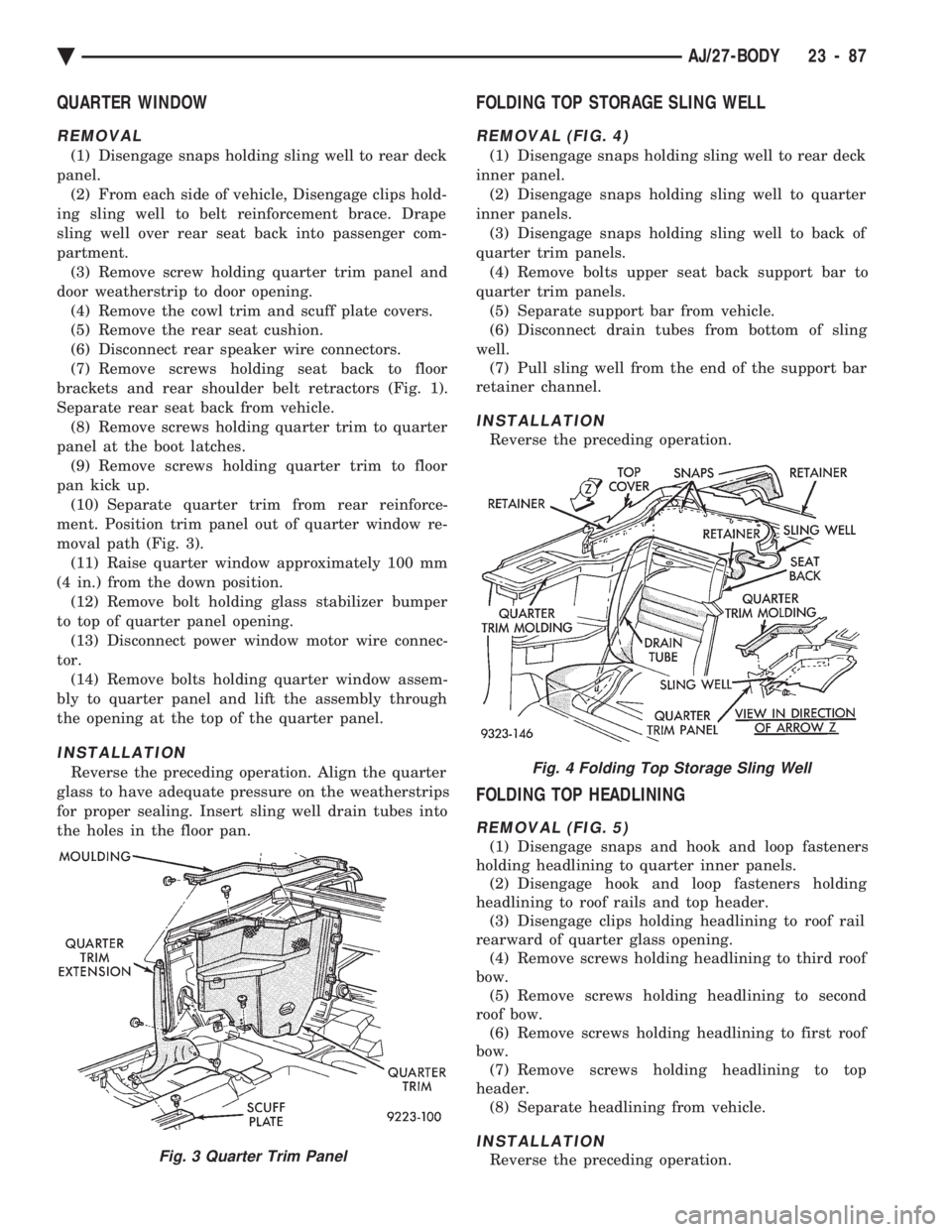
brackets and rear shoulder belt retractors (Fig. 1).
Separate rear seat back from vehicle. (8) Remove screws holding quarter trim to quarter
panel at the boot latches. (9) Remove screws holding quarter trim to floor
pan kick up. (10) Separate quarter trim from rear reinforce-
ment. Position trim panel out of quarter window re-
moval path (Fig. 3). (11) Raise quarter window approximately 100 mm
(4 in.) from the down position. (12) Remove bolt holding glass stabilizer bumper
to top of quarter panel opening. (13) Disconnect power window motor wire connec-
tor. (14) Remove bolts holding quarter window assem-
bly to quarter panel and lift the assembly through
the opening at the top of the quarter panel.
INSTALLATION
Reverse the preceding operation. Align the quarter
glass to have adequate pressure on the weatherstrips
for proper sealing. Insert sling well drain tubes into
the holes in the floor pan.
FOLDING TOP STORAGE SLING WELL
REMOVAL (FIG. 4)
(1) Disengage snaps holding sling well to rear deck
inner panel. (2) Disengage snaps holding sling well to quarter
inner panels. (3) Disengage snaps holding sling well to back of
quarter trim panels. (4) Remove bolts upper seat back support bar to
quarter trim panels. (5) Separate support bar from vehicle.
(6) Disconnect drain tubes from bottom of sling
well. (7) Pull sling well from the end of the support bar
retainer channel.
INSTALLATION
Reverse the preceding operation.
FOLDING TOP HEADLINING
REMOVAL (FIG. 5)
(1) Disengage snaps and hook and loop fasteners
holding headlining to quarter inner panels. (2) Disengage hook and loop fasteners holding
headlining to roof rails and top header. (3) Disengage clips holding headlining to roof rail
rearward of quarter glass opening. (4) Remove screws holding headlining to third roof
bow. (5) Remove screws holding headlining to second
roof bow. (6) Remove screws holding headlining to first roof
bow. (7) Remove screws holding headlining to top
header. (8) Separate headlining from vehicle.
INSTALLATION
Reverse the preceding operation.Fig. 3 Quarter Trim Panel
Fig. 4 Folding Top Storage Sling Well
Ä AJ/27-BODY 23 - 87
Page 2247 of 2438
(1) On old top cover mark a line from the top of
the quarter glass opening to the center of rear glass
opening on each side of the top. (2) Using a suitable cutting tool, cut the rear quar-
ter sections off of old top. (3) Mark locations of old top cover on side tack
strips. (4) Remove staples holding old top cover to side
tack strips. (5) Using quarter sections cut from old top cover as
a pattern, mark lower tack strip edge of new top to
same size and shape as old top. (6) Trim excess material from new top cover.
(7) Position side tack strips under edge of new top
and align index marks. (8) Install staples 100 mm (4 in.) apart to hold top
cover to side tack strips. (9) Install retainer rod in listing pockets on back of
top cover. (10) Position top cover over top bows on vehicle
and center top cover side to side. (11) Mate retainer rod to first roof bow.
(12) Install screws to hold top cover retainer rod to
first roof bow. (13) Mate retainer rod to second roof bow.
(14) Install screws to hold top cover retainer rod to
second roof bow. (15) Route roof rail tension cables through rear of
pockets on back of top cover. (16) Connect roof rail tension cables to key-hole
slots in roof rails. (17) Install rubber plugs to hold roof rail tension
cable ends into key-hold slots in roof rails. (18) Apply suitable contact adhesive to roof rail
rear of quarter glass opening and back of top cover
hold down listing. (19) Stick top cover listing to roof rail.
(20) Place roof rail weatherstrip channel in proper
position. (21) Install screws to hold channel to roof rail.
(22) Position top cover listing at index marks on
third roof bow. (23) Install staples 10 mm (0.3 in.) apart to hold
top cover listing to third roof bow. (24) Zip rear window into position.
(25) Fold rear of top cover, tack strips and rear
window down and over the third roof bow. (26) Position top cover at index marks on rear tack
strip. (27) Install staples 100 mm (4 in.) apart to hold
top cover to rear tack strip.
CAUTION: Cover all painted and upholstered sur-
faces to avoid damage while performing the follow-
ing operations.
(28) Reposition tack strips under rear deck and
quarter panels. (29) Place side tack strips in position behind quar-
ter panels. (30) Install enough bolts to temporarily hold side
tack strips to inside of quarter panels. (31) Place rear tack strip in position behind deck
panel. (32) Install enough bolts to temporarily hold rear
tack strip to inner deck panel. (33) Close and latch folding top.
(34) Pull top cover forward over top of windshield
and hold cover material taut. (35) Mark location of froward lower edge of top
header on top cover material. (36) Release top latches and lower top to mid-
point. (37) Align marks on top material to front lower
edge of top header. (38) Verify that top cover will be wrinkle free and
aligned side to side. (39) Install staples 10 mm (0.3 in.) apart to hold
top cover to header. (40) Place top header feature strip in position un-
der top header. (41) Install staples 10 mm (0.3 in.) apart to hold
feature strip to top header. (42) Place weatherstrip channel in position under
top header. (43) Install screws to hold channel to top header.
(44) Insert top header weatherstrip into header
and roof rail channels. (45) Install screws to hold roof rail tension cable
springs to roof rear roof rail behind quarter glass
opening. (46) Close and latch top windshield header.
(47) Inspect top cover for excess wrinkling. If ex-
cess wrinkles are apparent, the top cover must be re-
positioned on the tack strips. (48) If top cover is smooth, release top header
latches to allow top cover to relax. (49) Remove bolts holding tack strips to deck and
quarter panels. (50) Install staples 10 mm (0.3 in.) apart to hold
top cover to rear and side tack strips. (51) Place side and rear tack strips in position.
(52) Install bolts to hold tack strips to deck and
quarter panels. (53) Insert quarter glass weatherstrips into roof
rail channels. (54) Place sling well into position.
(55) Engage snaps to hold sling well to rear deck
and quarter panels. Verify that drain tube is con-
nected to bottom of sling well. (56) Install headlining.
(57) Close top and latch header to windshield
header.
Ä AJ/27-BODY 23 - 91
Page 2253 of 2438
AP-VEHICLE BODY COMPONENT SERVICE INDEX
page page
A-Pillar and Roof Rail Mouldings ............ 109
B-Pillar Trim PanelÐAP-44 Body ............ 109
Body Side Moulding and Applique ........... 108
Cowl Panel Trim and Scuff Plates ........... 109
Door Opening Weatherstrips ............... 107
Floor Carpet ........................... 113
Front Center Console .................... 113
Front Door and Hinge .................... 100
Front Door Belt Moulding and Weatherstrip .... 102
Front Door Glass ........................ 101
Front Door Glass Channel and Run Weatherstrip .......................... 103
Front Door Glass Run Lower Channels ....... 103
Front Door Latch ........................ 101
Front Door Side View Mirror ............... 101
Front Door Trim PanelÐAP-24/44 Body ....... 99
Front Door Water Shield .................. 100
Front Door Window Regulator/Manual ........ 103
Front Door Window Regulator/Power ......... 104
Front End Splash Shields .................. 99
Front Power Door Lock Actuator ............ 102
Front Seat BeltsÐAP-24 Body .............. 110
Front Seat BeltsÐAP-44 Body .............. 110
Front Seats ............................ 111
Grille .................................. 97
Grille Opening Panel ...................... 97
Head Lining ............................ 114
Hood and Hinges ........................ 97 Hood Latch and Release Cable
.............. 98
Lift Gate Luggage Rack ................... 116
Lift Gate Remote Release Cable ............ 115
Lower Quarter Trim PanelÐAP-44 Body ...... 109
Outside Front Door Latch Release Handle ..... 101
Outside Rear Door Latch Release Handle ..... 105
Overhead Console ....................... 113
Quarter Glass Weatherstrip ................ 108
Quarter Glass Window ................... 108
Quarter Trim PanelÐAP-44 Body ........... 109
Rear Door and Hinge .................... 104
Rear Door Belt Moulding and Weatherstrip .... 106
Rear Door Glass ........................ 106
Rear Door Glass Run Weatherstrip .......... 107
Rear Door Latch ........................ 105
Rear Door Silencer and Water Shield ........ 104
Rear Door Stationary Glass ................ 107
Rear Door Trim Panel .................... 104
Rear Door Window Regulator/Manual ........ 107
Rear Door Window Regulator/Power ......... 107
Rear Power Door Lock Actuator ............ 106
Rear Seat Belts ......................... 111
Rear Seats ............................ 112
Rear Window Glass ...................... 115
Sun Roof Air Deflector ................... 114
Sun Roof Drain Tubes .................... 115
Sun Roof Weatherstrip ................... 114
Upper Quarter Trim PanelÐAP-44 Body ...... 109
GRILLE
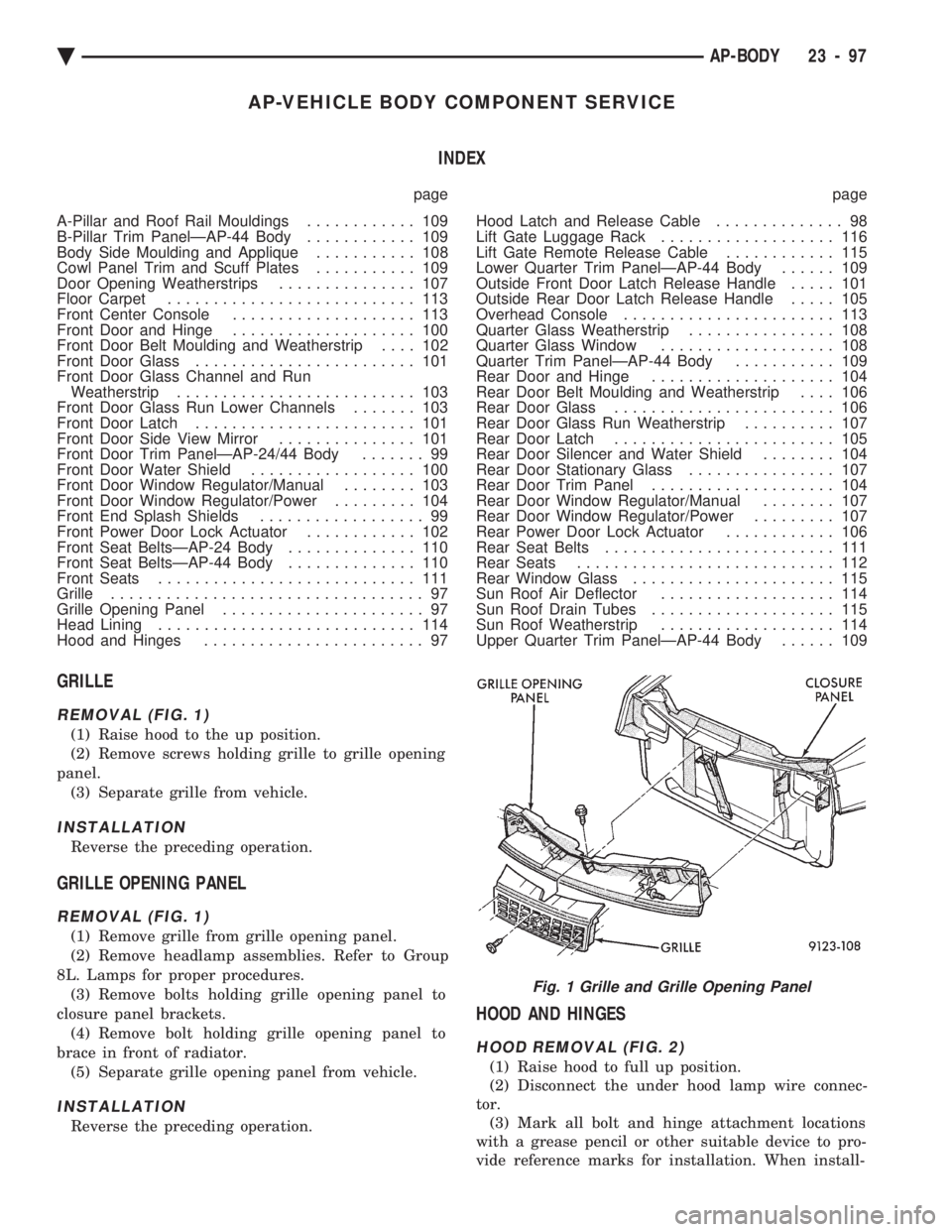
REMOVAL (FIG. 1)
(1) Raise hood to the up position.
(2) Remove screws holding grille to grille opening
panel. (3) Separate grille from vehicle.
INSTALLATION
Reverse the preceding operation.
GRILLE OPENING PANEL
REMOVAL (FIG. 1)
(1) Remove grille from grille opening panel.
(2) Remove headlamp assemblies. Refer to Group
8L. Lamps for proper procedures. (3) Remove bolts holding grille opening panel to
closure panel brackets. (4) Remove bolt holding grille opening panel to
brace in front of radiator. (5) Separate grille opening panel from vehicle.
INSTALLATION
Reverse the preceding operation.
HOOD AND HINGES
HOOD REMOVAL (FIG. 2)
(1) Raise hood to full up position.
(2) Disconnect the under hood lamp wire connec-
tor. (3) Mark all bolt and hinge attachment locations
with a grease pencil or other suitable device to pro-
vide reference marks for installation. When install-
Fig. 1 Grille and Grille Opening Panel
Ä AP-BODY 23 - 97
Page 2361 of 2438
INSTALLATION
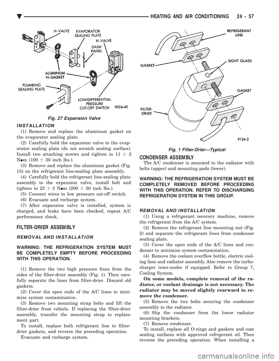
(1) Remove and replace the aluminum gasket on
the evaporator sealing plate. (2) Carefully hold the expansion valve to the evap-
orator sealing plate (do not scratch sealing surface).
Install two attaching screws and tighten to 11 63
N Im (100 630 inch lbs.).
(3) Remove and replace the aluminum gasket (Fig.
15) on the refrigerant line-sealing plate assembly. (4) Carefully hold the refrigerant line-sealing plate
assembly to the expansion valve, install bolt and
tighten to 23 63N Im (200 630 inch lbs.).
(5) Connect wires to low pressure cut-off switch.
(6) Evacuate and recharge system.
(7) After expansion valve is installed, system is
charged, and leaks have been checked, repeat A/C
performance check.
FILTER-DRIER ASSEMBLY
REMOVAL AND INSTALLATION
WARNING: THE REFRIGERATION SYSTEM MUST
BE COMPLETELY EMPTY BEFORE PROCEEDING
WITH THIS OPERATION.
(1) Remove the two high pressure lines from the
sides of the filter-drier assembly (Fig. 1). Then care-
fully separate the lines from filter-drier. Discard old
gaskets. (2) Cover the open ends of the A/C lines to mini-
mize system contamination. (3) Remove two mounting strap bolts and lift the
filter-drier from vehicle. If replacing the filter-drier
assembly, transfer the mounting strap to replace-
ment part. To install, replace both refrigerant line to filter-
drier gaskets, and reverse the preceding operation. Evacuate and recharge system.
CONDENSER ASSEMBLY
The A/C condenser is mounted to the radiator with
bolts (upper) and mounting pads (lower).
WARNING: THE REFRIGERATION SYSTEM MUST BE
COMPLETELY REMOVED BEFORE PROCEEDING
WITH THIS OPERATION. REFER TO DISCHARGING
REFRIGERATION SYSTEM IN THIS GROUP.
REMOVAL AND INSTALLATION
(1) Using a refrigerant recovery machine, remove
the refrigerant from the A/C system. (2) Remove the refrigerant line mounting nut (Fig.
2) and separate the refrigerant lines from condenser
sealing plate. (3) Cover the open ends of the A/C lines and con-
denser to minimize system contamination. (4) Remove the coolant overflow bottle, electric cool-
ing fans and radiator assembly. Also remove the turbo-
charger inter-cooler if equipped. Refer to Group 7,
Cooling System. On some models, complete removal of the ra-
diator, or coolant drainage is not necessary. The
radiator may be moved slightly rearward to re-
move the condenser. (5) Remove the two bolts securing the condenser
assembly to the radiator. (6) Slip the condenser from the lower radiator
mounting brackets. (7) Remove condenser.
To install, replace all O-rings and gaskets and coat
sealing surfaces with approved refrigerant oil. Then
reverse the preceding operation. When installing a
Fig. 27 Expansion Valve
Fig. 1 Filter-DrierÐTypical
Ä HEATING AND AIR CONDITIONING 24 - 57
Page 2366 of 2438
AA BODY PROCEDURE
WARNING: IF EQUIPPED WITH A/C, THE REFRIG-
ERATION SYSTEM MUST BE COMPLETELY EMPTY
BEFORE PROCEEDING WITH THIS OPERATION. Refer to Group 8E and Group 23 for component re-
moval and installation when performing this opera-
tion. (1) Perform steps 1 through 7 of Blower Motor re-
moval and installation. (2) Remove relay panel above glove compartment
opening. (3) Disconnect the A/C vacuum line connector and
radio noise capacitor connectors. (4) Remove left windshield pillar trim cover.
(5) Remove left lower side cowl trim cover.
(6) Remove hood release handle mechanism attach-
ing screws. (7) Remove steering column trim covers.
(8) Disconnect parking brake release mechanism
connecting rod. Gain access through fuse panel open-
ing. (9) Remove lower left instrument panel silencer.
(10) Remove lower left instrument panel reinforce-
ment. (11) Remove instrument panel center (radio) bezel.
(12) Remove forward floor console.
(13) Remove the radio.
(14) Remove the heater-A/C control.
(15) Remove cigar lighter.
(16) Remove message center/trip computer, if
equipped. (17) Disconnect side window demister tubes from
top of heat A/C unit. (18) Remove steering column upper attaching bolts
and allow the steering wheel to rest on the driver
seat cushion. (19) Remove upper instrument panel (defroster
outlet) cover. (20) Remove upper instrument panel attaching
screws from below the windshield opening. (21) Loosen (do not remove) the left lower cowl in-
strument panel attaching screw. (22) Remove the right lower cowl instrument panel
attaching screw.
CAUTION: Protect the passenger seat cover from
soiling or damage using a suitable cover.
(23) Carefully pull the right side of the instrument
panel away from the vehicle. Allow the instrument
panel to rest on the passenger seat cushion.
CAUTION: Before proceeding with the next opera-
tion, review the Safety Precautions and Warnings at
the front of this Group. (24) From the engine compartment, drain the cool-
ing system and disconnect the heater hoses from the
heater core nipples. Plug the nipples to avoid spilling
coolant inside the vehicle. (25) Disconnect the refrigerant lines from the ex-
pansion-valve at the dash panel on the right side of
the vehicle. Seal the refrigerant lines to prevent con-
tamination. (26) Remove the expansion valve from the evapo-
rator plate. Seal the valve to avoid contamination. (27) Remove the condensate drain tube.
(28) Remove heater-A/C unit to dash panel attach-
ing nuts. (29) From inside the vehicle, pull rearward on the
heater-A/C unit to clear the dash panel silencer and
remove the unit from the vehicle. To install, reverse the preceding operation. Refill
cooling system and test for leaks. Evacuate and
charge the refrigerant system and test overall perfor-
mance.
AG, AJ BODY PROCEDURE
WARNING: IF EQUIPPED WITH A/C, THE REFRIG-
ERATION SYSTEM MUST BE COMPLETELY EMPTY
BEFORE PROCEEDING WITH THIS OPERATION.
(1) Disconnect the battery negative cable.
(2) Drain the coolant from cooling system. Refer to
Group 7, Cooling System. (3) Remove the air conditioner expansion valve (if
equipped). (4) Disconnect the heater hoses from heater core.
Then plug or cap the tubes on heater core. This will
prevent spilling coolant into the interior of vehicle
during unit removal. (5) Remove the condensate drain tube.
(6) Disconnect the A/C-heater vacuum supply line
from vacuum supply nipple (in the engine compart-
ment). (7) Remove the four A/C-heater assembly-to-dash
panel attaching nuts. (8) Remove the passenger side front seat. Refer to
Group 23, Body. (9) Remove the kick panel/sill cover at right door
opening. (10) Remove the body computer (Fig. 6) located at
the lower right section of the right front door pillar. (11) Remove the glove box assembly. Refer to
Group 8E, Instrument Panel. (12) Remove the carpeted panels from both sides of
the console. (13) Un-clip the radio antenna cable from the
metal support (Fig. 6) located behind and below the
glove box opening. (14) Instrument panel removal is not necessary to
remove the A/C-heater assembly from the vehicle.
24 - 62 HEATING AND AIR CONDITIONING Ä