1993 CHEVROLET PLYMOUTH ACCLAIM drain bolt
[x] Cancel search: drain boltPage 1932 of 2438
(10) Connect negative cable back on negative post
of battery. (11) Start engine and turn steering wheel several
times from stop to stop to bleed air from fluid in sys-
tem. Stop engine, check fluid level, and inspect sys-
tem for leaks. See Checking Fluid Level.
3.0 LITER
REMOVE
(1) REMOVE THE (-) NEGATIVE BATTERY CA-
BLE FROM THE BATTERY AND ISOLATE CA-
BLE. (2) Remove the serpentine accessory drive belt
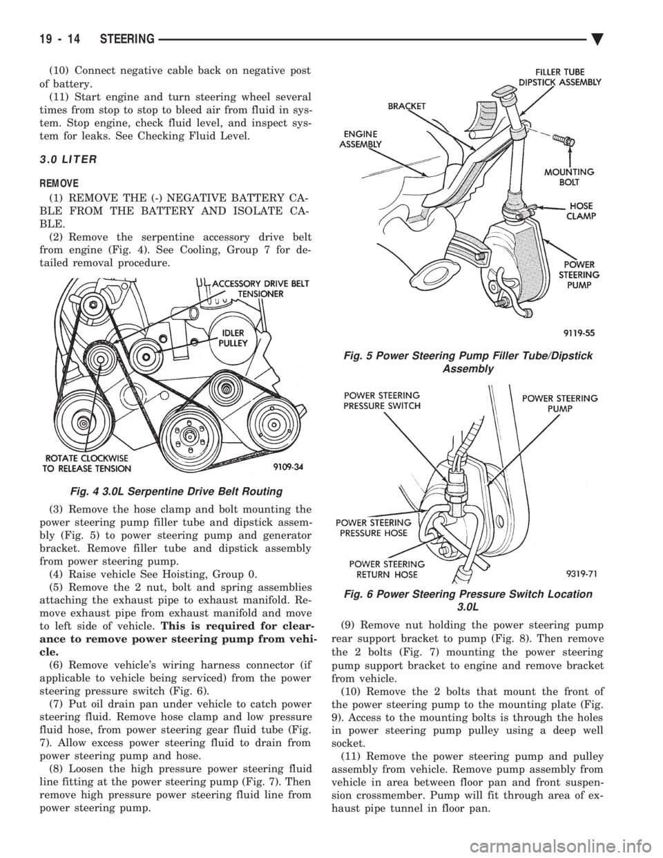
from engine (Fig. 4). See Cooling, Group 7 for de-
tailed removal procedure.
(3) Remove the hose clamp and bolt mounting the
power steering pump filler tube and dipstick assem-
bly (Fig. 5) to power steering pump and generator
bracket. Remove filler tube and dipstick assembly
from power steering pump. (4) Raise vehicle See Hoisting, Group 0.
(5) Remove the 2 nut, bolt and spring assemblies
attaching the exhaust pipe to exhaust manifold. Re-
move exhaust pipe from exhaust manifold and move
to left side of vehicle. This is required for clear-
ance to remove power steering pump from vehi-
cle. (6) Remove vehicle's wiring harness connector (if
applicable to vehicle being serviced) from the power
steering pressure switch (Fig. 6). (7) Put oil drain pan under vehicle to catch power
steering fluid. Remove hose clamp and low pressure
fluid hose, from power steering gear fluid tube (Fig.
7). Allow excess power steering fluid to drain from
power steering pump and hose. (8) Loosen the high pressure power steering fluid
line fitting at the power steering pump (Fig. 7). Then
remove high pressure power steering fluid line from
power steering pump. (9) Remove nut holding the power steering pump
rear support bracket to pump (Fig. 8). Then remove
the 2 bolts (Fig. 7) mounting the power steering
pump support bracket to engine and remove bracket
from vehicle. (10) Remove the 2 bolts that mount the front of
the power steering pump to the mounting plate (Fig.
9). Access to the mounting bolts is through the holes
in power steering pump pulley using a deep well
socket. (11) Remove the power steering pump and pulley
assembly from vehicle. Remove pump assembly from
vehicle in area between floor pan and front suspen-
sion crossmember. Pump will fit through area of ex-
haust pipe tunnel in floor pan.
Fig. 4 3.0L Serpentine Drive Belt Routing
Fig. 5 Power Steering Pump Filler Tube/Dipstick Assembly
Fig. 6 Power Steering Pressure Switch Location 3.0L
19 - 14 STEERING Ä
Page 1934 of 2438
(15) Start engine and turn steering wheel several
times from stop to stop to bleed air from fluid in sys-
tem. Stop engine, check fluid level, and inspect sys-
tem for leaks. See Checking Fluid Level.
3.3 & 3.8 LITER
REMOVE
(1) Remove the (-) negative battery cable from the
battery and isolate cable. (2) Remove the serpentine accessory drive belt
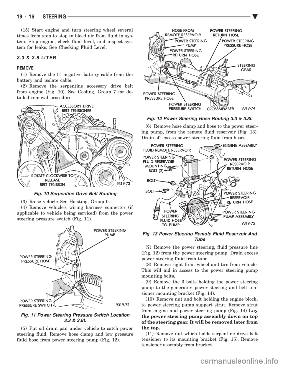
from engine (Fig. 10). See Cooling, Group 7 for de-
tailed removal procedure.
(3) Raise vehicle See Hoisting, Group 0.
(4) Remove vehicle's wiring harness connector (if
applicable to vehicle being serviced) from the power
steering pressure switch (Fig. 11).
(5) Put oil drain pan under vehicle to catch power
steering fluid. Remove hose clamp and low pressure
fluid hose from power steering pump (Fig. 12). (6) Remove hose clamp and hose to the power steer-
ing pump, from the remote fluid reservoir (Fig. 13).
Drain off excess power steering fluid from hoses.
(7) Remove the power steering, fluid pressure line
(Fig. 12) from the power steering pump. Drain excess
power steering fluid from tube. (8) Remove right front wheel and tire from vehicle.
This will aid in access to the power steering pump
mounting bolts. (9) Remove the 3 bolts holding the power steering
pump to the generator, power steering and belt ten-
sioner mounting bracket (Fig. 14). (10) Remove nut and bolt holding the engine block,
to power steering pump support strut. Remove strut
from engine and power steering pump (Fig. 14) Lay
the power steering pump assembly down on top
of the steering gear. It will be removed later from
the top. (11) Remove nut which holds serpentine drive belt
tensioner to its mounting bracket (Fig. 15). Remove
tensioner assembly from bracket.
Fig. 10 Serpentine Drive Belt Routing
Fig. 11 Power Steering Pressure Switch Location 3.3 & 3.8L
Fig. 12 Power Steering Hose Routing 3.3 & 3.8L
Fig. 13 Power Steering Remote Fluid Reservoir And Tube
19 - 16 STEERING Ä
Page 1937 of 2438
(18) Lower vehicle.
(19) Install the serpentine drive belt. Refer to (Fig.
10) for correct serpentine belt routing. See Cooling,
Group 7 for detailed installation procedure.
CAUTION: Do not use automatic transmission fluid
in power steering system. Only use Mopar T, Power
Steering Fluid, or equivalent.
(20) Fill power steering pump reservoir to correct
fluid level. (21) Connect the negative battery cable on the
negative battery post. (22) Start engine and turn steering wheel several
times from stop to stop to bleed air from fluid in sys-
tem. Stop engine, check fluid level, and inspect sys-
tem for leaks. See Checking Fluid Level.
TURBO III
REMOVE
(1) Disconnect the battery (-) negative cable from
the battery and isolate cable. (2) Raise vehicle See Hoisting, Group 0. Put oil
drain pan under vehicle to catch power steering
fluid. (3) Remove the right front underhood splash shield
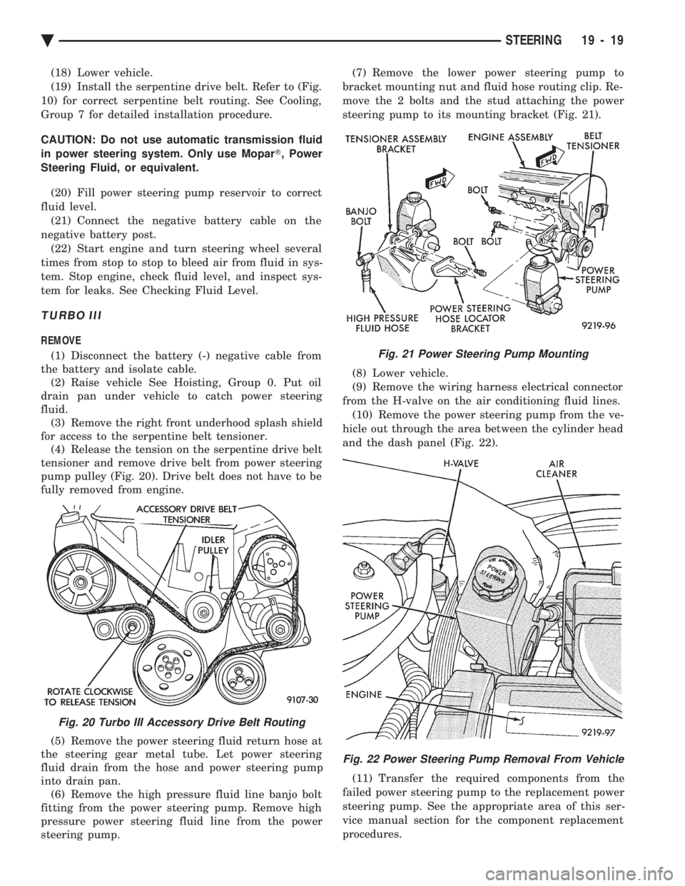
for access to the serpentine belt tensioner. (4) Release the tension on the serpentine drive belt
tensioner and remove drive belt from power steering
pump pulley (Fig. 20). Drive belt does not have to be
fully removed from engine.
(5) Remove the power steering fluid return hose at
the steering gear metal tube. Let power steering
fluid drain from the hose and power steering pump
into drain pan. (6) Remove the high pressure fluid line banjo bolt
fitting from the power steering pump. Remove high
pressure power steering fluid line from the power
steering pump. (7) Remove the lower power steering pump to
bracket mounting nut and fluid hose routing clip. Re-
move the 2 bolts and the stud attaching the power
steering pump to its mounting bracket (Fig. 21).
(8) Lower vehicle.
(9) Remove the wiring harness electrical connector
from the H-valve on the air conditioning fluid lines. (10) Remove the power steering pump from the ve-
hicle out through the area between the cylinder head
and the dash panel (Fig. 22).
(11) Transfer the required components from the
failed power steering pump to the replacement power
steering pump. See the appropriate area of this ser-
vice manual section for the component replacement
procedures.
Fig. 20 Turbo III Accessory Drive Belt Routing
Fig. 21 Power Steering Pump Mounting
Fig. 22 Power Steering Pump Removal From Vehicle
Ä STEERING 19 - 19
Page 1943 of 2438
POWER STEERING GEAR INDEX
page page
General Information ....................... 25
Outer Tie Rod ........................... 27 Steering Gear Service
..................... 25
GENERAL INFORMATION
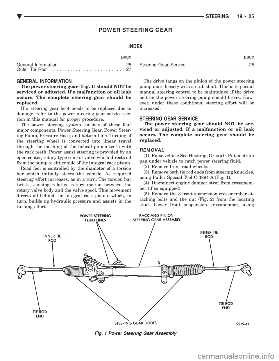
The power steering gear (Fig. 1) should NOT be
serviced or adjusted. If a malfunction or oil leak
occurs. The complete steering gear should be
replaced. If a steering gear boot needs to be replaced due to
damage, refer to the power steering gear service sec-
tion in this manual for proper procedure. The power steering system consists of these four
major components. Power Steering Gear, Power Steer-
ing Pump, Pressure Hose, and Return Line. Turning of
the steering wheel is converted into linear travel
through the meshing of the helical pinion teeth with
the rack teeth. Power assist steering is provided by an
open center, rotary type control valve which directs oil
from the pump to either side of the integral rack piston. Road feel is controlled by the diameter of a torsion
bar which initially steers the vehicle. As required
steering effort increases, as in a turn. The torsion bar
twists, causing relative rotary motion between the
rotary valve body and the valve spool. This movement
directs oil behind the integral rack piston, which, in
turn, builds up hydraulic pressure and assists in the
turning effort. The drive tangs on the pinion of the power steering
pump mate loosely with a stub shaft. This is to permit
manual steering control to be maintained if the drive
belt on the power steering pump should break. How-
ever, under these conditions, steering effort will be
increased.
STEERING GEAR SERVICE
The power steering gear should NOT be ser-
viced or adjusted. If a malfunction or oil leak
occurs. The complete steering gear should be
replaced.
REMOVAL
(1) Raise vehicle See Hoisting, Group 0. Put oil drain
pan under vehicle to catch power steering fluid. (2) Remove front road wheels.
(3) Remove both tie rod ends from steering knuckles,
using Puller Special Tool C-3894-A (Fig. 1). (4) Disconnect engine damper strut from crossmem-
ber (if so equipped). (5) Remove the 3 front suspension crossmember at-
taching bolts and the nut (Fig. 2) from the locating
stud. Lower front suspension crossmember, using
Fig. 1 Power Steering Gear Assembly
Ä STEERING 19 - 25
Page 1964 of 2438
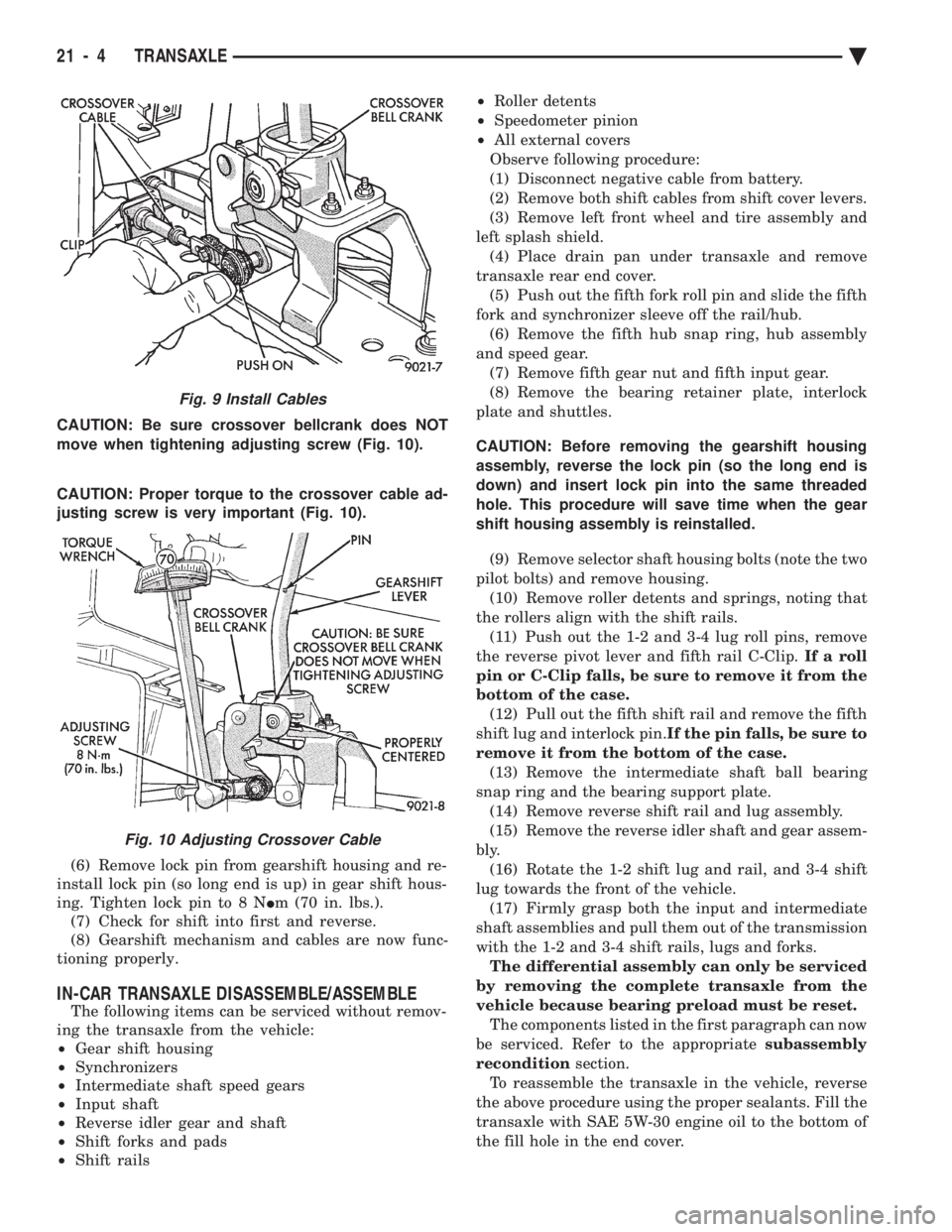
CAUTION: Be sure crossover bellcrank does NOT
move when tightening adjusting screw (Fig. 10).
CAUTION: Proper torque to the crossover cable ad-
justing screw is very important (Fig. 10).
(6) Remove lock pin from gearshift housing and re-
install lock pin (so long end is up) in gear shift hous-
ing. Tighten lock pin to 8 N Im (70 in. lbs.).
(7) Check for shift into first and reverse.
(8) Gearshift mechanism and cables are now func-
tioning properly.
IN-CAR TRANSAXLE DISASSEMBLE/ASSEMBLE
The following items can be serviced without remov-
ing the transaxle from the vehicle:
² Gear shift housing
² Synchronizers
² Intermediate shaft speed gears
² Input shaft
² Reverse idler gear and shaft
² Shift forks and pads
² Shift rails ²
Roller detents
² Speedometer pinion
² All external covers
Observe following procedure:
(1) Disconnect negative cable from battery.
(2) Remove both shift cables from shift cover levers.
(3) Remove left front wheel and tire assembly and
left splash shield. (4) Place drain pan under transaxle and remove
transaxle rear end cover. (5) Push out the fifth fork roll pin and slide the fifth
fork and synchronizer sleeve off the rail/hub. (6) Remove the fifth hub snap ring, hub assembly
and speed gear. (7) Remove fifth gear nut and fifth input gear.
(8) Remove the bearing retainer plate, interlock
plate and shuttles.
CAUTION: Before removing the gearshift housing
assembly, reverse the lock pin (so the long end is
down) and insert lock pin into the same threaded
hole. This procedure will save time when the gear
shift housing assembly is reinstalled. (9) Remove selector shaft housing bolts (note the two
pilot bolts) and remove housing. (10) Remove roller detents and springs, noting that
the rollers align with the shift rails. (11) Push out the 1-2 and 3-4 lug roll pins, remove
the reverse pivot lever and fifth rail C-Clip. If a roll
pin or C-Clip falls, be sure to remove it from the
bottom of the case. (12) Pull out the fifth shift rail and remove the fifth
shift lug and interlock pin. If the pin falls, be sure to
remove it from the bottom of the case. (13) Remove the intermediate shaft ball bearing
snap ring and the bearing support plate. (14) Remove reverse shift rail and lug assembly.
(15) Remove the reverse idler shaft and gear assem-
bly. (16) Rotate the 1-2 shift lug and rail, and 3-4 shift
lug towards the front of the vehicle. (17) Firmly grasp both the input and intermediate
shaft assemblies and pull them out of the transmission
with the 1-2 and 3-4 shift rails, lugs and forks. The differential assembly can only be serviced
by removing the complete transaxle from the
vehicle because bearing preload must be reset. The components listed in the first paragraph can now
be serviced. Refer to the appropriate subassembly
recondition section.
To reassemble the transaxle in the vehicle, reverse
the above procedure using the proper sealants. Fill the
transaxle with SAE 5W-30 engine oil to the bottom of
the fill hole in the end cover.
Fig. 9 Install Cables
Fig. 10 Adjusting Crossover Cable
21 - 4 TRANSAXLE Ä
Page 2000 of 2438
FLUID LEVEL AND CONDITION
The transmission and differential sump have a
common oil sump with a communicating opening
between the two. Before removing the dipstick, wipe all dirt off of the
protective disc and the dipstick handle. The torque converter will fill in both the PPark or N
Neutral positions. Place the selector lever in PPark to
check fluid level. Inspect fluid level on dipstick every six months.
Allow the engine to idle for at least one minute
with vehicle on level ground. This will assure
complete oil level stabilization between differen-
tial and transmission. A properly filled transaxle
will read near the addmark when fluid temperature is
21 degrees Celsius (70 degrees Fahrenheit). When the
transaxle reaches operating temperature the fluid
should be in the HOTregion.
Low fluid level can cause a variety of conditions
because it allows the pump to take in air along with the
fluid. As in any hydraulic system, air bubbles make the
fluid spongy, therefore, pressures will be low and build
up slowly. Improper filling can also raise the fluid level too
high. When the transaxle has too much fluid, the gears
churn up foam and cause the same conditions which
occur with a low fluid level. In either case, the air bubbles can cause overheating,
fluid oxidation, and varnishing, which can interfere
with normal valve, clutch, and servo operation. Foam-
ing can also result in fluid escaping from the transaxle
vent (dipstick handle) where it may be mistaken for a
leak. Along with fluid level, it is important to check the
condition of the fluid. When the fluid smells burned,
and is contaminated with metal or friction material
particles, a complete transaxle overhaul is needed. Be
sure to examine the fluid on the dipstick closely. If
there is any doubt about its condition, drain out a
sample for a double check. After the fluid has been checked, seat the dipstick
fully to seal out water and dirt.
SELECTION OF LUBRICANT
It is important that the proper lubricant be used in
these transmissions. MOPAR tATF PLUS (Automatic
Transmission Fluid-Type 7176) should be used to aid in
assuring optimum transmission performance. Fluids of
the type labeled DEXRON II Automatic Transmission
Fluid should be used only if the recommended fluid is
not available. It is important that the transmission
fluid be maintained at the prescribed level using the
recommended fluids.
SPECIAL ADDITIVES
Chrysler Corporation does not recommend the addi-
tion of any fluids to the transmission, other than the
automatic transmission fluid listed above. An ex- ception to this policy is the use of special dyes to aid in
detecting fluid leaks. The use of transmission sealers
should be avoided, since they may adversely affect
seals.
FLUID AND FILTER CHANGE
When the factory fill fluid is changed, only
fluids of the type labeled MOPAR tATF PLUS
(Automatic Transmission fluid) Type 7176 should
be used. A band adjustment and filter change
should be made at the time of the oil change. The
magnet (on the inside of the oil pan) should also
be cleaned with a clean, dry cloth. If the transaxle is disassembled for any reason,
the fluid and filter should be changed, and the
band(s) adjusted.
FLUID DRAIN AND REFILL
(1) Raise vehicle on a hoist (See Lubrication, Group
0). Place a drain container with a large opening, under
transaxle oil pan. (2) Loosen pan bolts and tap the pan at one corner to
break it loose allowing fluid to drain, then remove the
oil pan. (3) Install a new filter and gasket on bottom of the
valve body and tighten retaining screws to 5 N Im (40
in. lbs.). (4) Clean the oil pan and magnet. Reinstall pan
using new MOPAR tAdhesive sealant. Tighten oil pan
bolts to 19 N Im (165 in. lbs.).
(5) Pour four quarts of MOPAR tATF PLUS (Auto-
matic Transmission Fluid) Type 7176 through the
dipstick opening. (6) Start engine and allow to idle for at least one
minute. Then, with parking and service brakes ap-
plied, move selector lever momentarily to each posi-
tion, ending in the park or neutral position. (7) Add sufficient fluid to bring level to 1/8 inch
below the ADD mark. Recheck fluid level after transaxle is at normal
operating temperature. The level should be in the HOT
region (Fig. 1). To prevent dirt from entering transaxle, make cer-
tain that dipstick is full seated into the dipstick open-
ing.
TORQUE CONVERTER CLUTCH SOLENOID WIRING
CONNECTOR
If wiring connector is unplugged, the torque con-
verter clutch will not operate (Fig. 2).
ROAD TEST
Prior to performing a road test, be certain that the
fluid level and condition, and control cable adjustments
have been checked and approved. During the road test, the transaxle should be oper-
ated in each position to check for slipping and any
variation in shifting.
21 - 40 TRANSAXLE Ä
Page 2005 of 2438
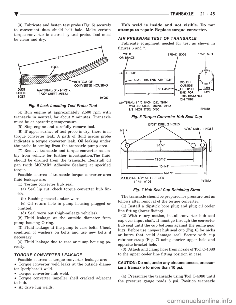
(3) Fabricate and fasten test probe (Fig. 5) securely
to convenient dust shield bolt hole. Make certain
torque converter is cleared by test probe. Tool must
be clean and dry.
(4) Run engine at approximately 2,500 rpm with
transaxle in neutral, for about 2 minutes. Transaxle
must be at operating temperature. (5) Stop engine and carefully remove tool.
(6) If upper surface of test probe is dry, there is no
torque converter leak. A path of fluid across probe
indicates a torque converter leak. Oil leaking under
the probe is coming from the transaxle pump area. (7) Remove transaxle and torque converter assem-
bly from vehicle for further investigation.The fluid
should be drained from the transaxle. Reinstall oil
pan (with MOPAR tAdhesive Sealant) at specified
torque. Possible sources of transaxle torque converter area
fluid leakage are: (1) Torque converter hub seal.(a) Seal lip cut, check torque converter hub fin-
ish. (b) Bushing moved and/or worn.
(c) Oil return hole in pump housing plugged or
omitted. (d) Seal worn out (high-mileage vehicles).
(2) Fluid leakage at the outside diameter from
pump housing O-ring. (3) Fluid leakage at the pump to case bolts. Check
condition of washers on bolts and use new bolts if
necessary. (4) Fluid leakage due to case or pump housing po-
rosity.
TORQUE CONVERTER LEAKAGE
Possible sources of torque converter leakage are:
² Torque converter weld leaks at the outside diame-
ter (peripheral) weld.
² Torque converter hub weld.
² Torque converter impeller shell cracked adjacent
to hub.
² At drive lug welds. Hub weld is inside and not visible. Do not
attempt to repair. Replace torque converter.
AIR PRESSURE TEST OF TRANSAXLE
Fabricate equipment needed for test as shown in
figures 6 and 7.
The transaxle should be prepared for pressure test as
follows after removal of the torque converter: (1) Install a dipstick bore plug and plug oil cooler
line fitting (lower fitting). (2) With rotary motion, install converter hub seal
cup over input shaft. It must go through the converter
hub seal until the cup bottoms against the pump gear
lugs. Before use, inspect hub seal cup (Fig. 6) for nicks
or burrs that could damage seal. Secure with cup
retainer strap (Fig. 7) using starter upper hole and
opposite bracket hole. (3) Attach and clamp hose from nozzle of Tool C-4080
to the upper cooler line fitting position in case.
CAUTION: Do not, under any circumstances, pressur-
ize a transaxle to more than 10 psi. (4) Pressurize the transaxle using Tool C-4080 until
the pressure gauge reads 8 psi. Position transaxle
Fig. 5 Leak Locating Test Probe Tool
Fig. 6 Torque Converter Hub Seal Cup
Fig. 7 Hub Seal Cup Retaining Strap
Ä TRANSAXLE 21 - 45
Page 2007 of 2438
BAND ADJUSTMENT
KICKDOWN BAND (FRONT)
The kickdown band adjusting screw is located on
left side (top front) of the transaxle case. (1) Loosen locknut and back off nut approximately
five turns. Test adjusting screw for free turning in
the transaxle case. (2) Using wrench, Tool C-3880-A with adapter Tool
C-3705, tighten band adjusting screw to 5 N Im (47 to
50 in. lbs.). If adapter C-3705 is not used, tighten ad-
justing screw to 8 N Im (72 in. lbs.) which is the true
torque. (3) Back off adjusting screw the number of turns
listed in Specifications . Hold adjusting screw in this
position and tighten locknut to 47 N Im (35 ft. lbs.)
LOW/REVERSE BAND-REAR
To adjust low-reverse band, proceed as follows:
(1) Loosen and back off locknut approximately 5
turns. (2) Using an inch-pound torque wrench, tighten
adjusting screw to 5 N Im (41 in. lbs.) true torque.
(3) Back off adjusting screw the number of turns
listed under Specifications in the rear of the Tran-
saxle Section in this service manual. (4) Tighten locknut to 14 N Im (10 ft. lbs.).
HYDRAULIC CONTROL PRESSURE ADJUSTMENTS
LINE PRESSURE
An incorrect throttle pressure setting will cause in-
correct line pressure readings even though line pres-
sure adjustment is correct. Always inspect and
correct throttle pressure adjustment before adjusting
the line pressure. The approximate adjustment for line pressure is
1-5/16 inches, measured from valve body to inner
edge of adjusting nut. However, due to manufactur-
ing tolerances, the adjustment can be varied to ob-
tain specified line pressure. The adjusting screw may be turned with an Allen
wrench. One complete turn of adjusting screw
changes closed throttle line pressure approximately
1-2/3 psi. Turning adjusting screw counterclockwise
increases pressure, and clockwise decreases pressure.
THROTTLE PRESSURE
Throttle pressures cannot be tested accurately;
therefore, the adjustment should be measured if a
malfunction is evident. (1) Insert gauge pin of Tool C-3763 between the
throttle lever cam and kickdown valve. (2) By pushing in on tool, compress kickdown
valve against its spring so throttle valve is com-
pletely bottomed inside the valve body. (3) While compressing spring, turn throttle lever
stop screw with adapter C-4553. Turn until head of screw touches throttle lever tang, with throttle lever
cam touching tool and throttle valve bottomed. Be sure
adjustment is made with spring fully compressed and
valve bottomed in the valve body.
VEHICLE SPEED SENSOR PINION GEAR
When the speed sensor is removed for any reason, a
NEW O-ring must be installed on its outside diameter.
REMOVAL AND INSTALLATION
(1) Remove speedometer cable (if so equipped).
(2) Remove harness connector from sensor. Make
sure weatherseal stays on harness connector. (3) Remove bolt securing the distance sensor in the
extension housing. (4) Carefully pull sensor and pinion gear assembly
out of extension housing. (5) Remove pinion gear from sensor.
(6) To install, reverse the above procedure. Make
sure extension housing and sensor flange are clean
prior to installation. Always use a NEW sensor O-ring. (7) Tighten securing bolt to 7 N Im (60 in. lbs.).
Tighten speedometer cable to 4 N Im (35 in. lbs.).
PARK/NEUTRAL POSITION AND BACK-UP LAMP
SWITCH
REPLACEMENT AND TEST
The Park/Neutral switch is the center terminal of the
3 terminal switch. It provides ground for the starter
solenoid circuit through the selector lever in only Park
and Neutral positions. (1) To test switch, remove wiring connector from
switch and test for continuity between center pin of
switch and transaxle case. Continuity should exist only
when transaxle is in Park or Neutral. (2) Check gearshift cable adjustment before replac-
ing a switch which tests bad. (3) Unscrew switch from transaxle case allowing
fluid to drain into a container. Move selector lever to
Park and then to Neutral positions. Inspect to see that
the switch operating lever fingers are centered in
switch opening in the case. (4) Screw the switch with a new seal into transaxle
case and tighten to 33 N Im (24 ft. lbs.). Retest switch
with the test lamp. (5) Add fluid to transaxle to bring up to proper level.
(6) The back-up lamp switch circuit is through the
two outside terminals of the 3 terminal switch. (7) To test switch, remove wiring connector from
switch and test for continuity between the two outside
pins. (8) Continuity should exist only with transaxle in
Reverse position. (9) No continuity should exist from either pin to the
case.
Ä TRANSAXLE 21 - 47