1993 CHEVROLET PLYMOUTH ACCLAIM drain bolt
[x] Cancel search: drain boltPage 1667 of 2438
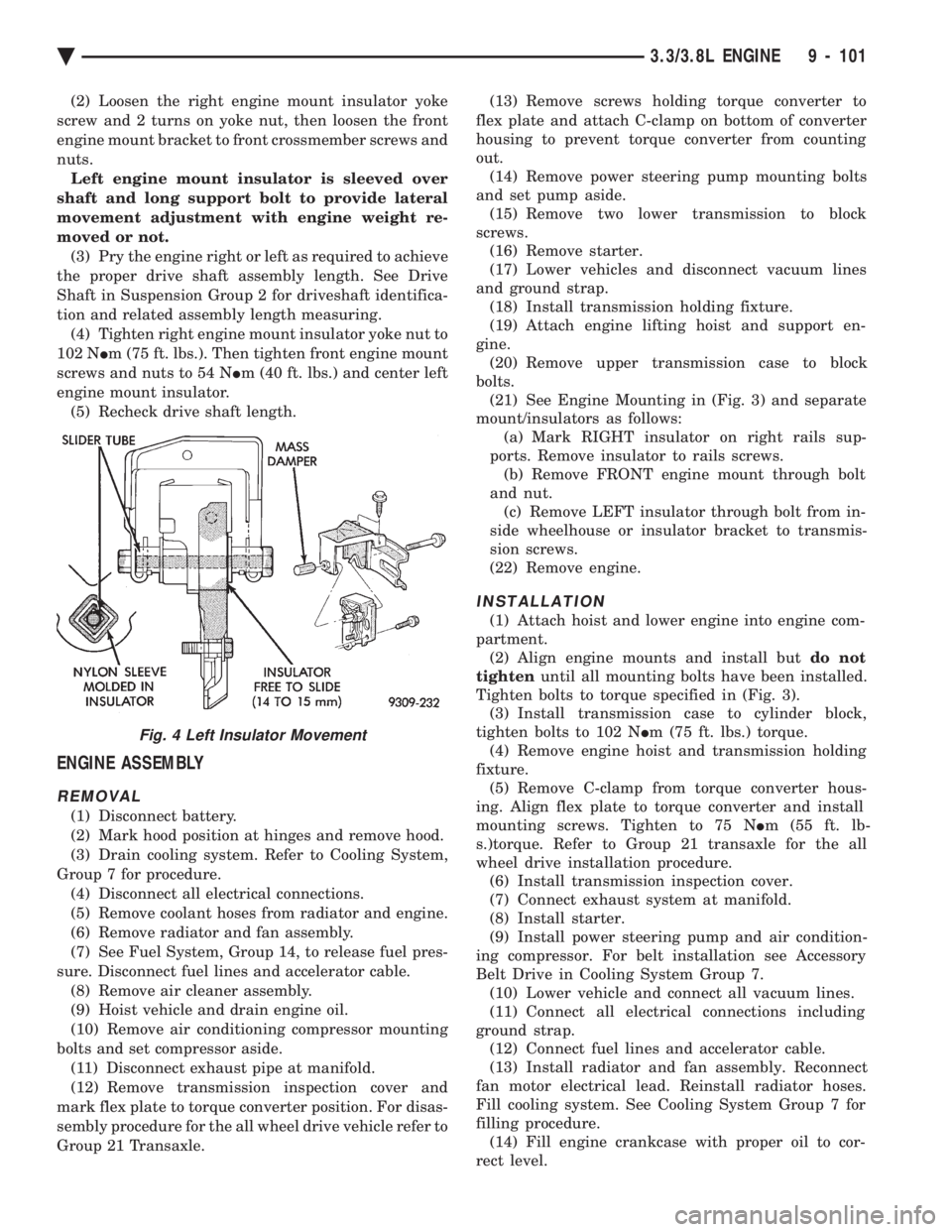
(2) Loosen the right engine mount insulator yoke
screw and 2 turns on yoke nut, then loosen the front
engine mount bracket to front crossmember screws and
nuts. Left engine mount insulator is sleeved over
shaft and long support bolt to provide lateral
movement adjustment with engine weight re-
moved or not. (3) Pry the engine right or left as required to achieve
the proper drive shaft assembly length. See Drive
Shaft in Suspension Group 2 for driveshaft identifica-
tion and related assembly length measuring. (4) Tighten right engine mount insulator yoke nut to
102 N Im (75 ft. lbs.). Then tighten front engine mount
screws and nuts to 54 N Im (40 ft. lbs.) and center left
engine mount insulator. (5) Recheck drive shaft length.
ENGINE ASSEMBLY
REMOVAL
(1) Disconnect battery.
(2) Mark hood position at hinges and remove hood.
(3) Drain cooling system. Refer to Cooling System,
Group 7 for procedure. (4) Disconnect all electrical connections.
(5) Remove coolant hoses from radiator and engine.
(6) Remove radiator and fan assembly.
(7) See Fuel System, Group 14, to release fuel pres-
sure. Disconnect fuel lines and accelerator cable. (8) Remove air cleaner assembly.
(9) Hoist vehicle and drain engine oil.
(10) Remove air conditioning compressor mounting
bolts and set compressor aside. (11) Disconnect exhaust pipe at manifold.
(12) Remove transmission inspection cover and
mark flex plate to torque converter position. For disas-
sembly procedure for the all wheel drive vehicle refer to
Group 21 Transaxle. (13) Remove screws holding torque converter to
flex plate and attach C-clamp on bottom of converter
housing to prevent torque converter from counting
out. (14) Remove power steering pump mounting bolts
and set pump aside. (15) Remove two lower transmission to block
screws. (16) Remove starter.
(17) Lower vehicles and disconnect vacuum lines
and ground strap. (18) Install transmission holding fixture.
(19) Attach engine lifting hoist and support en-
gine. (20) Remove upper transmission case to block
bolts. (21) See Engine Mounting in (Fig. 3) and separate
mount/insulators as follows: (a) Mark RIGHT insulator on right rails sup-
ports. Remove insulator to rails screws. (b) Remove FRONT engine mount through bolt
and nut. (c) Remove LEFT insulator through bolt from in-
side wheelhouse or insulator bracket to transmis-
sion screws.
(22) Remove engine.
INSTALLATION
(1) Attach hoist and lower engine into engine com-
partment. (2) Align engine mounts and install but do not
tighten until all mounting bolts have been installed.
Tighten bolts to torque specified in (Fig. 3). (3) Install transmission case to cylinder block,
tighten bolts to 102 N Im (75 ft. lbs.) torque.
(4) Remove engine hoist and transmission holding
fixture. (5) Remove C-clamp from torque converter hous-
ing. Align flex plate to torque converter and install
mounting screws. Tighten to 75 N Im (55 ft. lb-
s.)torque. Refer to Group 21 transaxle for the all
wheel drive installation procedure. (6) Install transmission inspection cover.
(7) Connect exhaust system at manifold.
(8) Install starter.
(9) Install power steering pump and air condition-
ing compressor. For belt installation see Accessory
Belt Drive in Cooling System Group 7. (10) Lower vehicle and connect all vacuum lines.
(11) Connect all electrical connections including
ground strap. (12) Connect fuel lines and accelerator cable.
(13) Install radiator and fan assembly. Reconnect
fan motor electrical lead. Reinstall radiator hoses.
Fill cooling system. See Cooling System Group 7 for
filling procedure. (14) Fill engine crankcase with proper oil to cor-
rect level.
Fig. 4 Left Insulator Movement
Ä 3.3/3.8L ENGINE 9 - 101
Page 1668 of 2438
(15) Install hood.
(16) Connect battery.
(17) Start engine and run until operating temper-
ature is reached. (18) Adjust transmission or linkage if necessary.
ROCKER ARMS AND SHAFT ASSEMBLY
REMOVAL
(1) Remove upper intake manifold assembly. Refer
to Intake and Exhaust Manifolds, Group 11. (2) Disconnect spark plug wires by pulling on the
boot straight out in line with plug. (3) Disconnect closed ventilation system and evap-
oration control system from cylinder head cover. (4) Remove cylinder head cover and gasket.
(5) Remove four rocker shaft bolts and retainers.
(6) Remove rocker arms and shaft assembly.
(7) If rocker arm assemblies are disassembled for
cleaning or replacement. Assemble rocker arms in
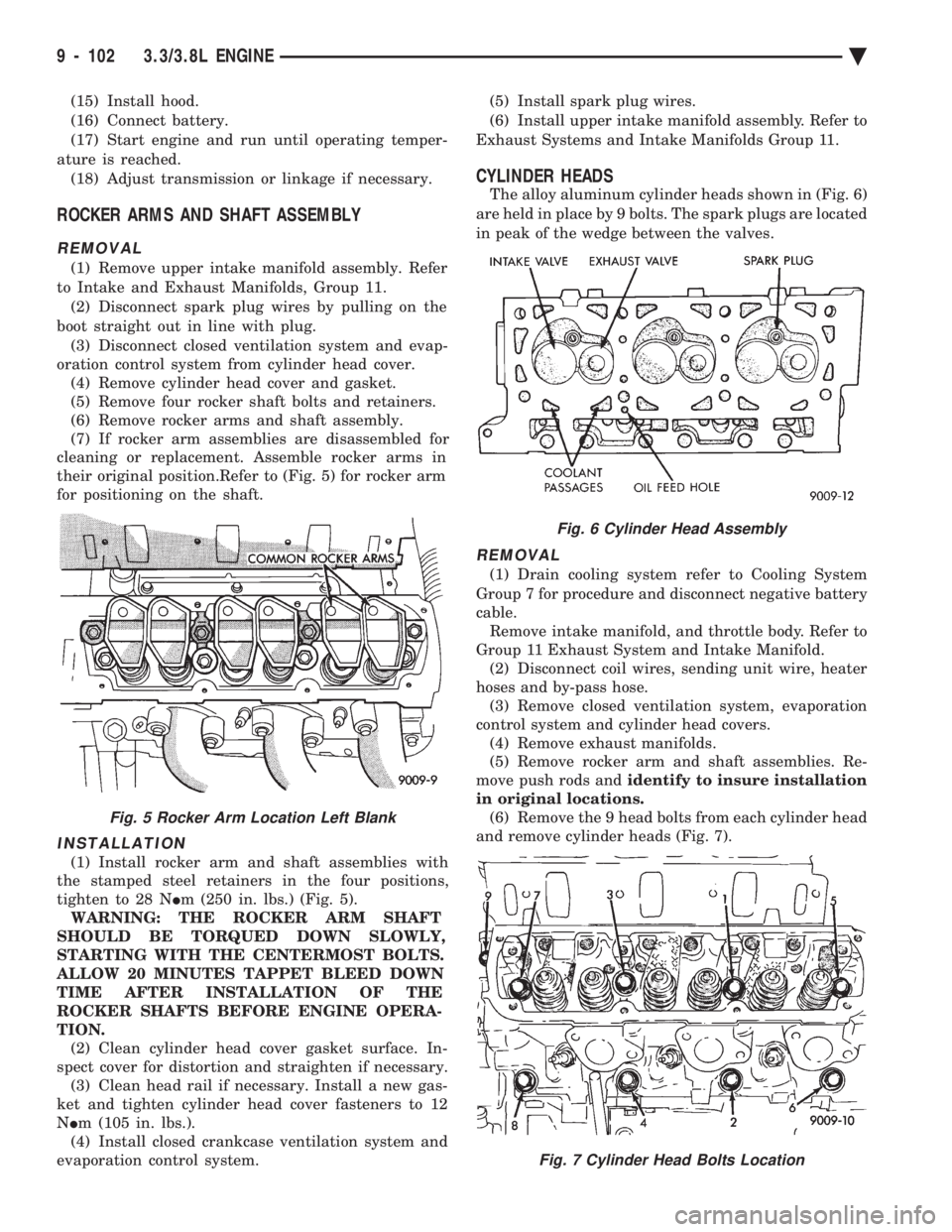
their original position.Refer to (Fig. 5) for rocker arm
for positioning on the shaft.
INSTALLATION
(1) Install rocker arm and shaft assemblies with
the stamped steel retainers in the four positions,
tighten to 28 N Im (250 in. lbs.) (Fig. 5).
WARNING: THE ROCKER ARM SHAFT
SHOULD BE TORQUED DOWN SLOWLY,
STARTING WITH THE CENTERMOST BOLTS.
ALLOW 20 MINUTES TAPPET BLEED DOWN
TIME AFTER INSTALLATION OF THE
ROCKER SHAFTS BEFORE ENGINE OPERA-
TION. (2) Clean cylinder head cover gasket surface. In-
spect cover for distortion and straighten if necessary. (3) Clean head rail if necessary. Install a new gas-
ket and tighten cylinder head cover fasteners to 12
N Im (105 in. lbs.).
(4) Install closed crankcase ventilation system and
evaporation control system. (5) Install spark plug wires.
(6) Install upper intake manifold assembly. Refer to
Exhaust Systems and Intake Manifolds Group 11.
CYLINDER HEADS
The alloy aluminum cylinder heads shown in (Fig. 6)
are held in place by 9 bolts. The spark plugs are located
in peak of the wedge between the valves.
REMOVAL
(1) Drain cooling system refer to Cooling System
Group 7 for procedure and disconnect negative battery
cable. Remove intake manifold, and throttle body. Refer to
Group 11 Exhaust System and Intake Manifold. (2) Disconnect coil wires, sending unit wire, heater
hoses and by-pass hose. (3) Remove closed ventilation system, evaporation
control system and cylinder head covers. (4) Remove exhaust manifolds.
(5) Remove rocker arm and shaft assemblies. Re-
move push rods and identify to insure installation
in original locations. (6) Remove the 9 head bolts from each cylinder head
and remove cylinder heads (Fig. 7).
Fig. 5 Rocker Arm Location Left Blank
Fig. 6 Cylinder Head Assembly
Fig. 7 Cylinder Head Bolts Location
9 - 102 3.3/3.8L ENGINE Ä
Page 1678 of 2438
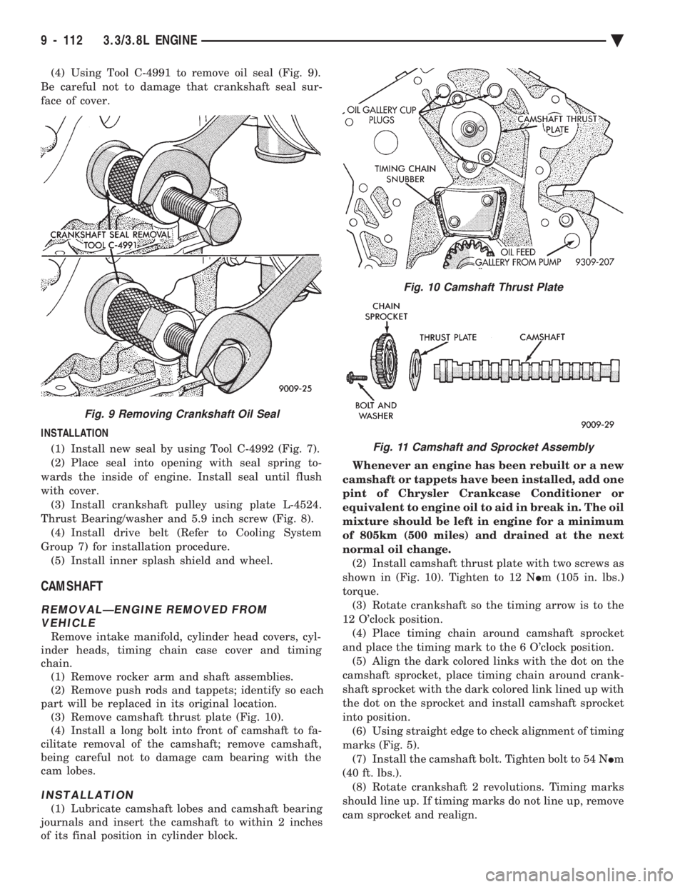
(4) Using Tool C-4991 to remove oil seal (Fig. 9).
Be careful not to damage that crankshaft seal sur-
face of cover.
INSTALLATION (1) Install new seal by using Tool C-4992 (Fig. 7).
(2) Place seal into opening with seal spring to-
wards the inside of engine. Install seal until flush
with cover. (3) Install crankshaft pulley using plate L-4524.
Thrust Bearing/washer and 5.9 inch screw (Fig. 8). (4) Install drive belt (Refer to Cooling System
Group 7) for installation procedure. (5) Install inner splash shield and wheel.
CAMSHAFT
REMOVALÐENGINE REMOVED FROM VEHICLE
Remove intake manifold, cylinder head covers, cyl-
inder heads, timing chain case cover and timing
chain. (1) Remove rocker arm and shaft assemblies.
(2) Remove push rods and tappets; identify so each
part will be replaced in its original location. (3) Remove camshaft thrust plate (Fig. 10).
(4) Install a long bolt into front of camshaft to fa-
cilitate removal of the camshaft; remove camshaft,
being careful not to damage cam bearing with the
cam lobes.
INSTALLATION
(1) Lubricate camshaft lobes and camshaft bearing
journals and insert the camshaft to within 2 inches
of its final position in cylinder block. Whenever an engine has been rebuilt or a new
camshaft or tappets have been installed, add one
pint of Chrysler Crankcase Conditioner or
equivalent to engine oil to aid in break in. The oil
mixture should be left in engine for a minimum
of 805km (500 miles) and drained at the next
normal oil change. (2) Install camshaft thrust plate with two screws as
shown in (Fig. 10). Tighten to 12 N Im (105 in. lbs.)
torque. (3) Rotate crankshaft so the timing arrow is to the
12 O'clock position. (4) Place timing chain around camshaft sprocket
and place the timing mark to the 6 O'clock position. (5) Align the dark colored links with the dot on the
camshaft sprocket, place timing chain around crank-
shaft sprocket with the dark colored link lined up with
the dot on the sprocket and install camshaft sprocket
into position. (6) Using straight edge to check alignment of timing
marks (Fig. 5). (7) Install the camshaft bolt. Tighten bolt to 54 N Im
(40 ft. lbs.). (8) Rotate crankshaft 2 revolutions. Timing marks
should line up. If timing marks do not line up, remove
cam sprocket and realign.
Fig. 9 Removing Crankshaft Oil Seal
Fig. 10 Camshaft Thrust Plate
Fig. 11 Camshaft and Sprocket Assembly
9 - 112 3.3/3.8L ENGINE Ä
Page 1708 of 2438
CAUTION: When using the ASD Fuel System Test,
the Auto Shutdown (ASD) relay will remain ener-
gized for 7 minutes or until the ignition switch is
turned to the OFF position, or Stop All Test is se-
lected.
TURBOCHARGER
REMOVAL
The turbocharger is removed from below the vehi-
cle. Cylinder head removal for component accessibil-
ity is not required. (1) Disconnect negative battery cable. Remove Air
Cleaner assembly (Fig. 1). (2) From Above: Remove front engine mount
through bolt and rotate engine (Top) forward away
from cowl. Refer to Engine Removal in Engine,
Group 9. (3) Remove Air Cleaner Support (Fig. 1).
(4) Disconnect Heated Oxygen sensor lead wire
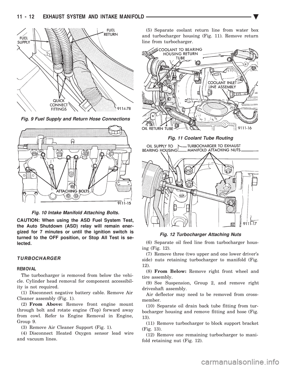
and vacuum lines. (5) Separate coolant return line from water box
and turbocharger housing (Fig. 11). Remove return
line from turbocharger.
(6) Separate oil feed line from turbocharger hous-
ing (Fig. 12). (7) Remove three (two upper and one lower driver's
side) nuts retaining turbocharger to manifold (Fig.
12). (8) From Below: Remove right front wheel and
tire assembly. (9) See Suspension, Group 2, and remove right
driveshaft assembly. Air deflector may need to be removed from cross-
member. (10) Separate oil drain back tube fitting from tur-
bocharger housing and remove fitting and hose (Fig.
13). (11) Remove turbocharger to block support bracket
(Fig. 13). (12) Remove one remaining turbocharger to mani-
fold retaining nut (Fig. 12).
Fig. 11 Coolant Tube Routing
Fig. 12 Turbocharger Attaching Nuts
Fig. 9 Fuel Supply and Return Hose Connections
Fig. 10 Intake Manifold Attaching Bolts.
11 - 12 EXHAUST SYSTEM AND INTAKE MANIFOLD Ä
Page 1709 of 2438
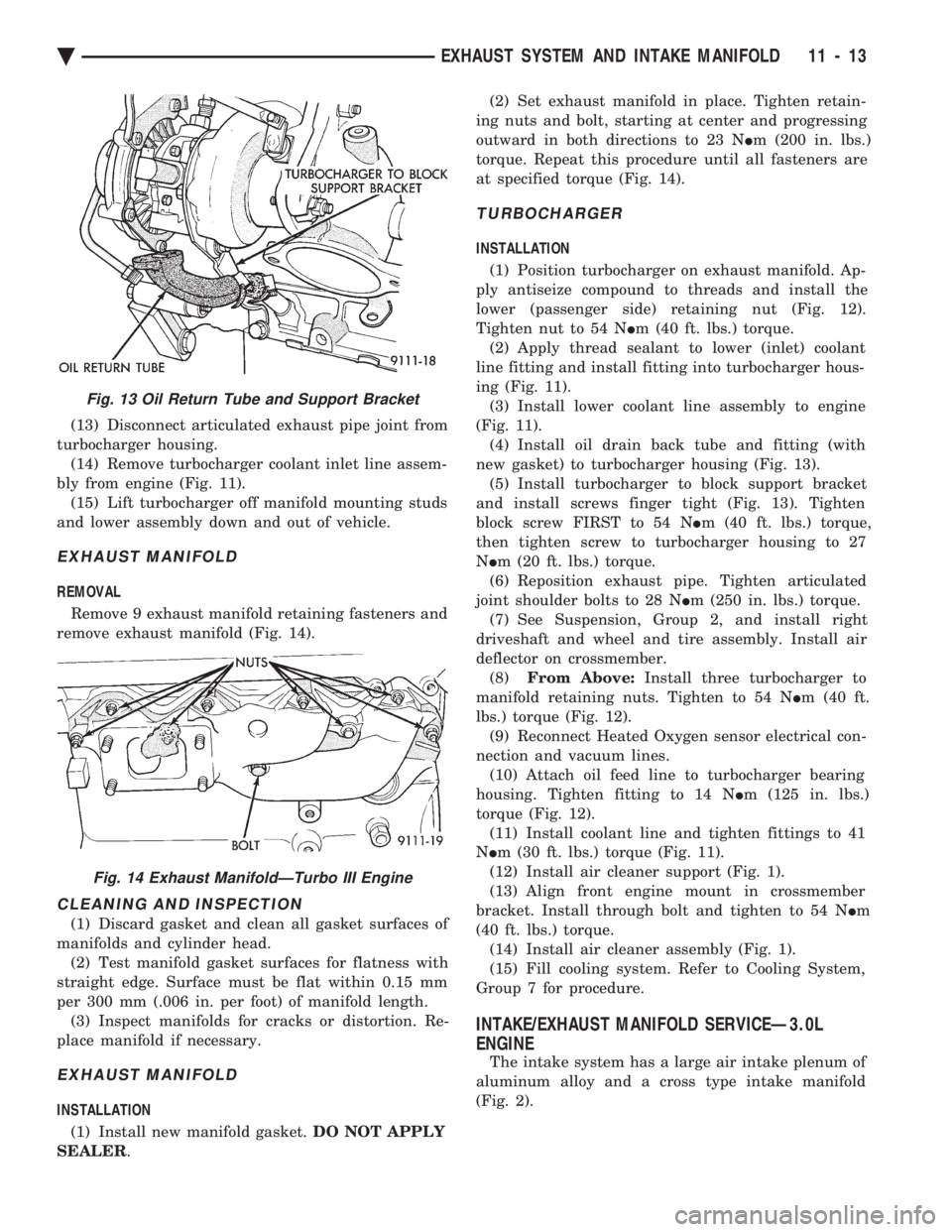
(13) Disconnect articulated exhaust pipe joint from
turbocharger housing. (14) Remove turbocharger coolant inlet line assem-
bly from engine (Fig. 11). (15) Lift turbocharger off manifold mounting studs
and lower assembly down and out of vehicle.
EXHAUST MANIFOLD
REMOVAL
Remove 9 exhaust manifold retaining fasteners and
remove exhaust manifold (Fig. 14).
CLEANING AND INSPECTION
(1) Discard gasket and clean all gasket surfaces of
manifolds and cylinder head. (2) Test manifold gasket surfaces for flatness with
straight edge. Surface must be flat within 0.15 mm
per 300 mm (.006 in. per foot) of manifold length. (3) Inspect manifolds for cracks or distortion. Re-
place manifold if necessary.
EXHAUST MANIFOLD
INSTALLATION
(1) Install new manifold gasket. DO NOT APPLY
SEALER . (2) Set exhaust manifold in place. Tighten retain-
ing nuts and bolt, starting at center and progressing
outward in both directions to 23 N Im (200 in. lbs.)
torque. Repeat this procedure until all fasteners are
at specified torque (Fig. 14).
TURBOCHARGER
INSTALLATION
(1) Position turbocharger on exhaust manifold. Ap-
ply antiseize compound to threads and install the
lower (passenger side) retaining nut (Fig. 12).
Tighten nut to 54 N Im (40 ft. lbs.) torque.
(2) Apply thread sealant to lower (inlet) coolant
line fitting and install fitting into turbocharger hous-
ing (Fig. 11). (3) Install lower coolant line assembly to engine
(Fig. 11). (4) Install oil drain back tube and fitting (with
new gasket) to turbocharger housing (Fig. 13). (5) Install turbocharger to block support bracket
and install screws finger tight (Fig. 13). Tighten
block screw FIRST to 54 N Im (40 ft. lbs.) torque,
then tighten screw to turbocharger housing to 27
N Im (20 ft. lbs.) torque.
(6) Reposition exhaust pipe. Tighten articulated
joint shoulder bolts to 28 N Im (250 in. lbs.) torque.
(7) See Suspension, Group 2, and install right
driveshaft and wheel and tire assembly. Install air
deflector on crossmember. (8) From Above: Install three turbocharger to
manifold retaining nuts. Tighten to 54 N Im (40 ft.
lbs.) torque (Fig. 12). (9) Reconnect Heated Oxygen sensor electrical con-
nection and vacuum lines. (10) Attach oil feed line to turbocharger bearing
housing. Tighten fitting to 14 N Im (125 in. lbs.)
torque (Fig. 12). (11) Install coolant line and tighten fittings to 41
N Im (30 ft. lbs.) torque (Fig. 11).
(12) Install air cleaner support (Fig. 1).
(13) Align front engine mount in crossmember
bracket. Install through bolt and tighten to 54 N Im
(40 ft. lbs.) torque. (14) Install air cleaner assembly (Fig. 1).
(15) Fill cooling system. Refer to Cooling System,
Group 7 for procedure.
INTAKE/EXHAUST MANIFOLD SERVICEÐ3.0L
ENGINE
The intake system has a large air intake plenum of
aluminum alloy and a cross type intake manifold
(Fig. 2).
Fig. 13 Oil Return Tube and Support Bracket
Fig. 14 Exhaust ManifoldÐTurbo III Engine
Ä EXHAUST SYSTEM AND INTAKE MANIFOLD 11 - 13
Page 1715 of 2438
(2) Attach exhaust pipe to exhaust manifold and
tighten shoulder bolt to 28 N Im (250 in. lbs.)
(3) Attach crossover pipe to exhaust manifold and
tighten bolt to 69 N Im (51 ft. lbs.)
(4) Connect heated oxygen sensor lead (Fig. 18).
(5) Install front exhaust manifold and attach ex-
haust crossover. (6) Install front manifold heat shield and tighten
attaching screws to 15 N Im (130 in. lbs.) (Fig. 2).
INTAKE/EXHAUST MANIFOLD SERVICEÐ3.3/3.8L
ENGINES
INTAKE MANIFOLD
REMOVAL
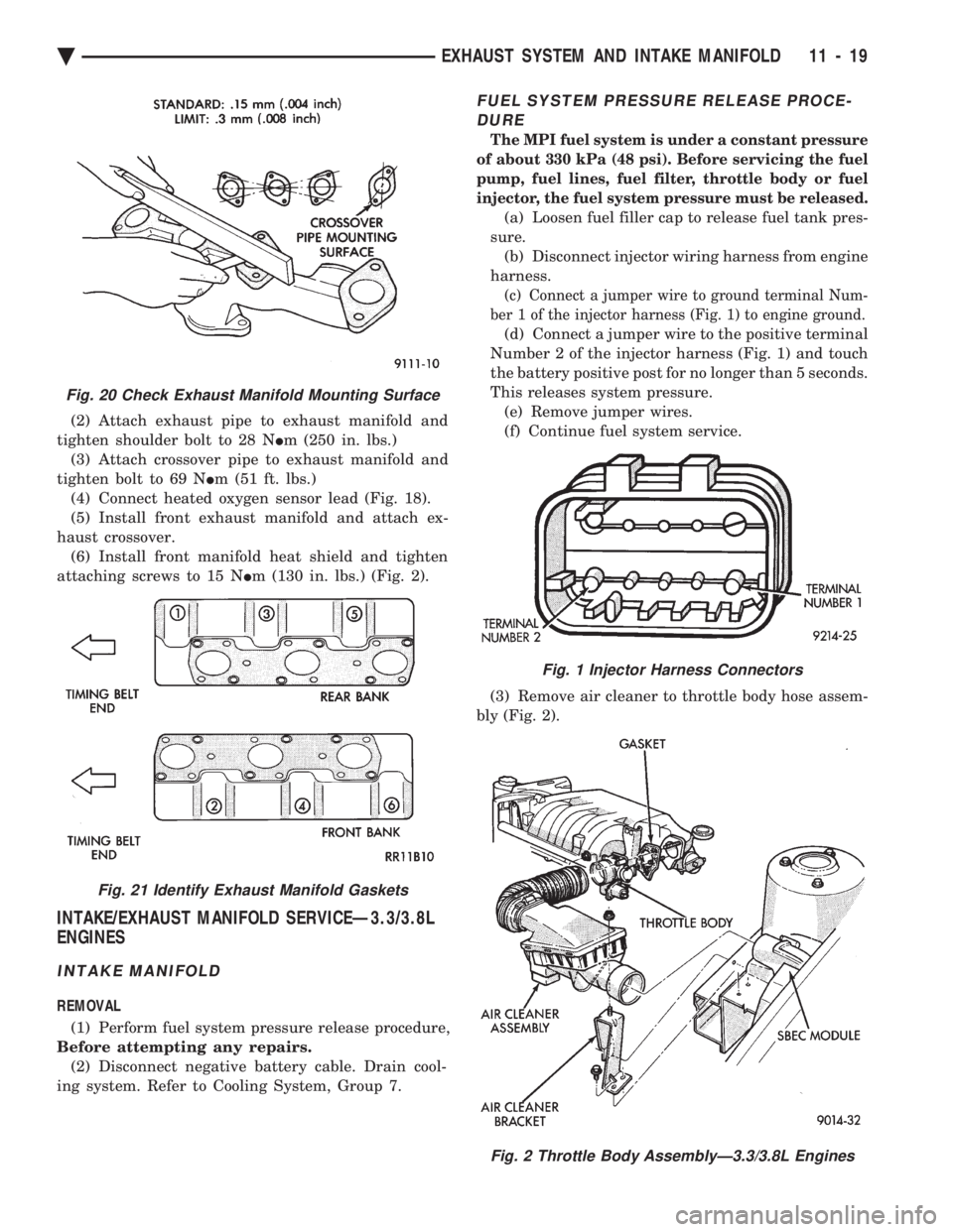
(1) Perform fuel system pressure release procedure,
Before attempting any repairs. (2) Disconnect negative battery cable. Drain cool-
ing system. Refer to Cooling System, Group 7.
FUEL SYSTEM PRESSURE RELEASE PROCE- DURE
The MPI fuel system is under a constant pressure
of about 330 kPa (48 psi). Before servicing the fuel
pump, fuel lines, fuel filter, throttle body or fuel
injector, the fuel system pressure must be released.
(a) Loosen fuel filler cap to release fuel tank pres-
sure. (b) Disconnect injector wiring harness from engine
harness.
(c) Connect a jumper wire to ground terminal Num-
ber 1 of the injector harness (Fig. 1) to engine ground.
(d) Connect a jumper wire to the positive terminal
Number 2 of the injector harness (Fig. 1) and touch
the battery positive post for no longer than 5 seconds.
This releases system pressure. (e) Remove jumper wires.
(f) Continue fuel system service.
(3) Remove air cleaner to throttle body hose assem-
bly (Fig. 2).
Fig. 20 Check Exhaust Manifold Mounting Surface
Fig. 21 Identify Exhaust Manifold Gaskets
Fig. 1 Injector Harness Connectors
Fig. 2 Throttle Body AssemblyÐ3.3/3.8L Engines
Ä EXHAUST SYSTEM AND INTAKE MANIFOLD 11 - 19
Page 1929 of 2438
INSTALL
(1) Install power steering pressure switch into fit-
ting on power steering pressure hose by hand until
fully seated. Then torque power steering pressure
switch to 12 N Im (106 in. lbs.).
(2) Install vehicle wiring harness connector onto
power steering pressure switch. Be sure latch on wir-
ing harness connector is fully engaged with locking
tab on power steering pressure switch.
CAUTION: Do not use automatic transmission fluid
in power steering system. Only use Mopar T, Power
Steering Fluid, or equivalent.
(3) Fill power steering pump reservoir to correct
fluid level. (4) Connect negative cable back on negative post of
battery. (5) Start engine and turn steering wheel several
times from stop to stop to bleed air from fluid in sys-
tem. Stop engine, check fluid level, and inspect sys-
tem for leaks. See Checking Fluid Level.
POWER STEERING HOSES
Service all power steering hoses with the vehicle
raised on a hoist. Cap all open ends of hoses, power
steering pump fittings and steering gear ports to pre-
vent entry of foreign material into the components.
WARNING: POWER STEERING OIL, ENGINE PARTS
AND EXHAUST SYSTEM MAY BE EXTREMELY HOT
IF ENGINE HAS BEEN RUNNING. DO NOT START
ENGINE WITH ANY LOOSE OR DISCONNECTED
HOSES. DO NOT ALLOW HOSES TO TOUCH HOT
EXHAUST MANIFOLD OR CATALYST.
For part reference and part location on the vehicle
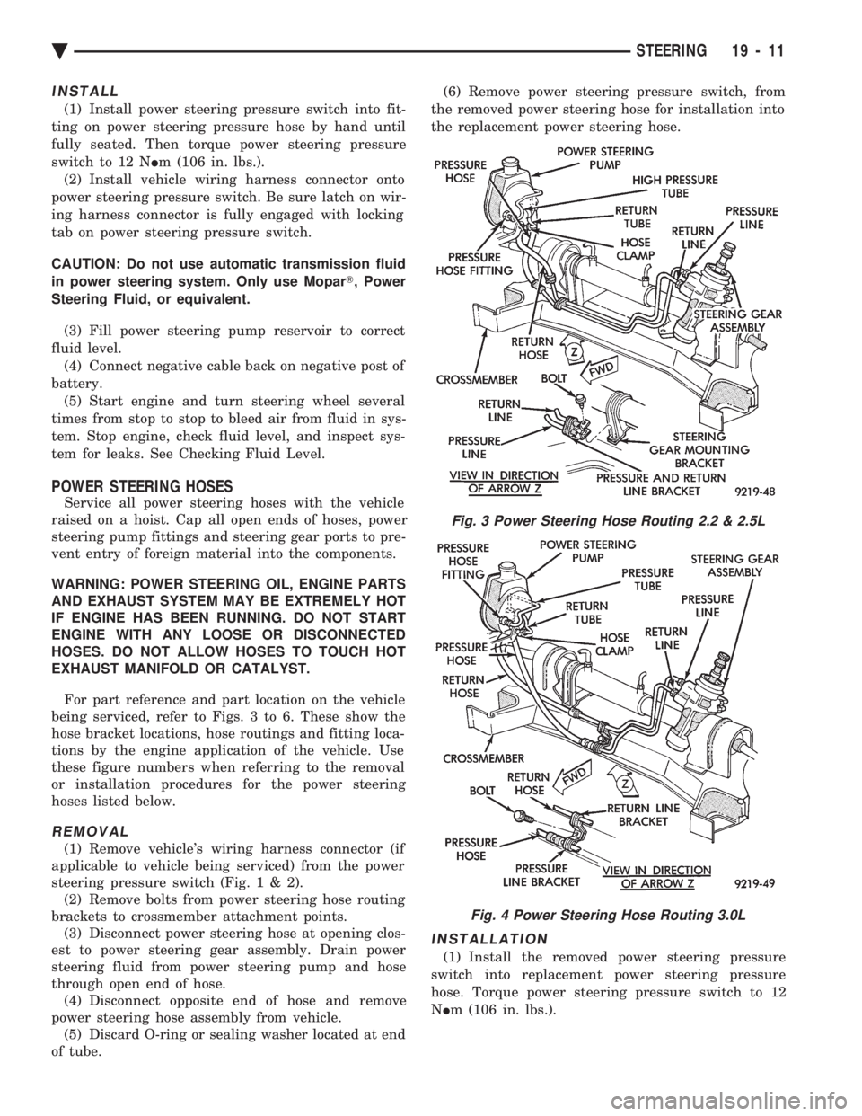
being serviced, refer to Figs. 3 to 6. These show the
hose bracket locations, hose routings and fitting loca-
tions by the engine application of the vehicle. Use
these figure numbers when referring to the removal
or installation procedures for the power steering
hoses listed below.
REMOVAL
(1) Remove vehicle's wiring harness connector (if
applicable to vehicle being serviced) from the power
steering pressure switch (Fig .1&2).
(2) Remove bolts from power steering hose routing
brackets to crossmember attachment points. (3) Disconnect power steering hose at opening clos-
est to power steering gear assembly. Drain power
steering fluid from power steering pump and hose
through open end of hose. (4) Disconnect opposite end of hose and remove
power steering hose assembly from vehicle. (5) Discard O-ring or sealing washer located at end
of tube. (6) Remove power steering pressure switch, from
the removed power steering hose for installation into
the replacement power steering hose.
INSTALLATION
(1) Install the removed power steering pressure
switch into replacement power steering pressure
hose. Torque power steering pressure switch to 12
N Im (106 in. lbs.).
Fig. 3 Power Steering Hose Routing 2.2 & 2.5L
Fig. 4 Power Steering Hose Routing 3.0L
Ä STEERING 19 - 11
Page 1930 of 2438
(2) Using a lint free towel, wipe clean open power
steering hose ends, power steering pump and steer-
ing gear ports. (3) Install new O-rings or sealing washers on the
ends of the power steering hoses. Lubricate O-rings
or sealing washers using clean power steering fluid. (4) Attach power steering hose to proper connec-
tions at power steering pump and steering gear. Cor-
rectly route power steering hoses avoiding tight
bends or kinking of the hose. Install power steering hose to crossmember routing bracket.
Hoses must
remain away from exhaust system, vehicle com-
ponents and unfriendly surfaces causing pos-
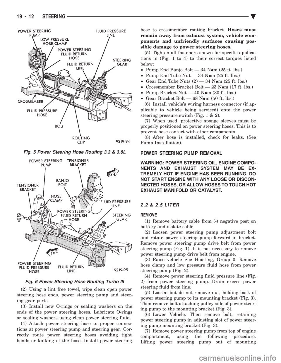
sible damage to power steering hoses. (5) Tighten all fasteners shown for specific applica-
tions in (Fig. 1 to 4) to their correct torques listed
below:
² Pump End Banjo Bolt Ð 34 N Im (25 ft. lbs.)
² Pump End Tube Nut Ð 34 N Im (25 ft. lbs.)
² Gear End Tube Nuts (2) Ð 34 N Im (25 ft. lbs.)
² Crossmember Bracket Bolt Ð 23 N Im (17 ft. lbs.)
² Pump Bracket Nut Ð 40 N Im (30 ft. lbs.)
² Gear Bracket Bolt Ð 68 N Im (50 ft. lbs.)
(6) Install vehicle's wiring harness connector (if ap-
plicable to vehicle being serviced) onto the power
steering pressure switch (Fig .1&2).
(7) When used, protective sponge sleeves must be
properly positioned on power steering hoses. This is to
prevent hose contact with other components. (8) After hose is installed, check for leaks. (See
Pump Installation).
POWER STEERING PUMP REMOVAL
WARNING: POWER STEERING OIL, ENGINE COMPO-
NENTS AND EXHAUST SYSTEM MAY BE EX-
TREMELY HOT IF ENGINE HAS BEEN RUNNING. DO
NOT START ENGINE WITH ANY LOOSE OR DISCON-
NECTED HOSES, OR ALLOW HOSES TO TOUCH HOT
EXHAUST MANIFOLD OR CATALYST.
2.2 & 2.5 LITER
REMOVE
(1) Remove battery cable from (-) negative post on
battery and isolate cable. (2) Loosen power steering pump adjustment bolt
and rotate power steering pump forward in bracket.
Remove power steering pump drive belt from power
steering pump (Fig. 1). It is not necessary to remove
power steering pump drive belt from engine. (3) Raise vehicle See Hoisting, Group 0. Remove
hose clamp and low pressure fluid hose from power
steering pump (Fig. 2). (4) Remove power steering fluid pressure line (Fig.
2) from power steering pump. Drain excess power
steering fluid from line. (5) Loosen but do not remove nut, holding back of
power steering pump to its mounting bracket (Fig. 3).
Then remove bolt attaching pulley side of power steer-
ing pump to the mounting bracket (Fig. 3). (6) Lower Vehicle. Then remove bolt, retaining
power steering pump in adjusting slot of power steer-
ing pump mounting bracket (Fig. 3). (7) Remove power steering pump from top of engine
compartment, using the following procedure.
Lifting power steering pump out of mounting
Fig. 5 Power Steering Hose Routing 3.3 & 3.8L
Fig. 6 Power Steering Hose Routing Turbo III
19 - 12 STEERING Ä