1993 CHEVROLET PLYMOUTH ACCLAIM drain bolt
[x] Cancel search: drain boltPage 352 of 2438
SERVICE PROCEDURES INDEX
page page
Automatic Transmission Oil Coolers .......... 23
Coolant ................................ 14
Coolant Recovery System (CRS) ............. 17
Cooling System Drain, Clean, Flush and Refill . . 15
Electric Fan Motor ........................ 22
Engine Thermostats ....................... 13
Fan Shroud ............................. 23 Fans
.................................. 21
Radiator Hoses .......................... 21
Radiator Pressure Cap .................... 18
Radiators ............................... 18
Testing System for Leaks .................. 17
Water Pumps ........................... 10
WATER PUMPS
A quick test to tell whether or not the pump is
working is to see if the heater warms properly. A
defective pump will not be able to circulate heated
coolant through the long heater hose. The water pump on all models can be replaced
without discharging the air conditioning system.
WATER PUMPÐ2.2/2.5L ENGINE
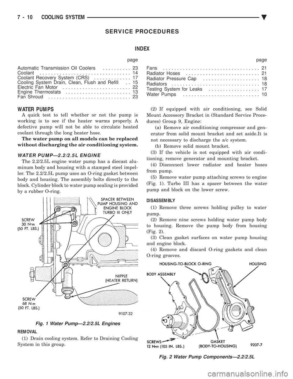
The 2.2/2.5L engine water pump has a diecast alu-
minum body and housing with a stamped steel impel-
ler. The 2.2/2.5L pump uses an O-ring gasket between
body and housing. The assembly bolts directly to the
block. Cylinder block to water pump sealing is provided
by a rubber O-ring.
REMOVAL (1) Drain cooling system. Refer to Draining Cooling
System in this group. (2) If equipped with air conditioning, see Solid
Mount Accessory Bracket in (Standard Service Proce-
dures) Group 9, Engine: (a) Remove air conditioning compressor and gen-
erator from solid mount bracket and set aside.It is
not necessary to discharge the a/c system. (b) Remove solid mount bracket.
(3) If the vehicle is not equipped with air condi-
tioning, remove generator and mounting bracket. (4) Disconnect lower radiator and heater hoses
from pump. (5) Remove water pump attaching screws to engine
(Fig. 1). Turbo III has a spacer between the water
pump and block on the lower screw.
DISASSEMBLY (1) Remove three screws holding pulley to water
pump. (2) Remove nine screws holding water pump body
to housing. Remove the pump body from housing
(Fig. 2). (3) Clean gasket surfaces on water pump housing
and engine block. (4) Remove and discard O-ring gaskets and clean
O-ring grooves.
Fig. 2 Water Pump ComponentsÐ2.2/2.5L
Fig. 1 Water PumpÐ2.2/2.5L Engines
7 - 10 COOLING SYSTEM Ä
Page 353 of 2438
INSPECTION Replace water pump body assembly if it has any of
these defects: (1) Cracks or damage on the body.
(2) Water leaks from the shaft seal, evident by
coolant traces below the vent hole. (3) Loose or rough turning bearing.
(4) Impeller rubs either the pump body or the hous-
ing.
ASSEMBLY
Body assembly and housing are serviced as separate
components. (1) Install new O-ring gasket in body O-ring groove.
(2) Assemble pump body to housing and tighten nine
screws to 12 N Im (105 in. lbs.) (Fig. 2).
(3) Rotate pump by hand to check for freedom of
movement. (4) Position water pump pulley to water pump.In-
stall three screws and tighten to 30 N Im (250 in. lbs.).
(5) Position new O-ring in housing to block O-ring
groove.
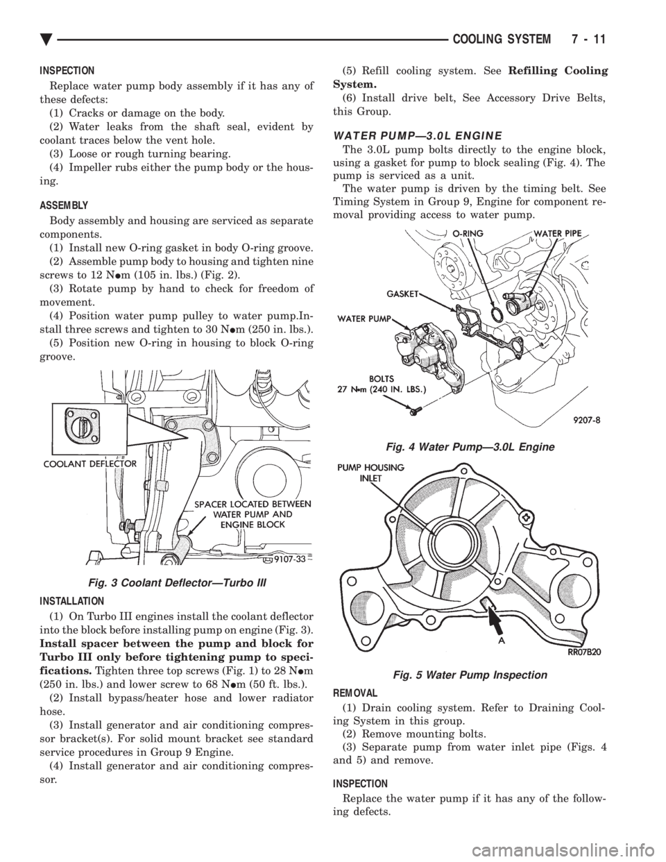
INSTALLATION (1) On Turbo III engines install the coolant deflector
into the block before installing pump on engine (Fig. 3).
Install spacer between the pump and block for
Turbo III only before tightening pump to speci-
fications. Tighten three top screws (Fig. 1) to 28 N Im
(250 in. lbs.) and lower screw to 68 N Im (50 ft. lbs.).
(2) Install bypass/heater hose and lower radiator
hose. (3) Install generator and air conditioning compres-
sor bracket(s). For solid mount bracket see standard
service procedures in Group 9 Engine. (4) Install generator and air conditioning compres-
sor. (5) Refill cooling system. See
Refilling Cooling
System. (6) Install drive belt, See Accessory Drive Belts,
this Group.
WATER PUMPÐ3.0L ENGINE
The 3.0L pump bolts directly to the engine block,
using a gasket for pump to block sealing (Fig. 4). The
pump is serviced as a unit. The water pump is driven by the timing belt. See
Timing System in Group 9, Engine for component re-
moval providing access to water pump.
REMOVAL (1) Drain cooling system. Refer to Draining Cool-
ing System in this group. (2) Remove mounting bolts.
(3) Separate pump from water inlet pipe (Figs. 4
and 5) and remove.
INSPECTION Replace the water pump if it has any of the follow-
ing defects.
Fig. 4 Water PumpÐ3.0L Engine
Fig. 5 Water Pump Inspection
Fig. 3 Coolant DeflectorÐTurbo III
Ä COOLING SYSTEM 7 - 11
Page 354 of 2438

(1) Damage or cracks on the pump body.
(2) Coolant leaks, if the shaft seal is leaking, evi-
dent by traces of coolant leaks from vent hole A in
(Fig. 5). (3) Impeller rubs inside of pump.
(4) Excessively loose or rough turning bearing.
INSTALLATION (1) Clean all gasket and O-ring surfaces on pump
and water pipe inlet tube. (2) Install new O-ring on water inlet pipe (Fig. 6).
Wet the O-ring with water to facilitate assembly.
CAUTION: Keep the O-ring free of oil or grease.
(3) Install new gasket on water pump and install
pump inlet opening over water pipe, press assembly
to cause water pipe insertion into pump housing. (4) Install pump to block mounting bolts and
tighten to 27 N Im (20 ft. lbs.).
(5) See Timing System in Engine, Group 9 and in-
stall timing belt. Reassemble engine. (6) Fill cooling system. See Refilling Cooling Sys-
tem.
WATER PUMPÐ3.3L AND 3.8L ENGINES
The pump has a die cast aluminum body and a
stamped steel impeller. It bolts directly to the chain
case cover, using an O-ring for sealing. It is driven
by the back surface of the Poly-V Drive Belt.
REMOVAL (1) Drain Cooling System. Refer to Draining Cool-
ing System in this group. (2) Remove Poly V Drive Belt.
(3) Remove right front lower fender shield.
(4) Remove pump pulley bolts and remove pulley.
(5) Remove pump mounting screws (Fig. 7). Re-
move pump. (6) Remove and discard O-ring seal. (7) Clean O-ring groove and O-ring surfaces on
pump and chain case cover. Take care not to scratch
or gouge sealing surface.
INSPECTION
Replace the water pump if it has any of the follow-
ing defects. (1) Damage or cracks on the pump body.
(2) Coolant leaks; if the seal is leaking, evident by
traces of coolant leaks from vent hole. (3) Loose or rough turning bearing.
(4) Impeller rubs either the pump body or chain-
case cover.
INSTALLATION
(1) Install new O-ring in O-ring groove (Fig. 8).
(2) Install pump to chain case cover. Torque screws
to 12 N Im (105 in. lbs.).
(3) Rotate pump by hand to check for freedom of
movement. (4) Position pulley on pump. Install screws and
torque to 30 N Im (250 in. lbs.).
Fig. 6 Water Pipe O-Ring
Fig. 7 Water PumpÐ3.3L and 3.8L Engines
Fig. 8 Water Pump Body
7 - 12 COOLING SYSTEM Ä
Page 355 of 2438

(5) Install drive belt. See Accessory Drive Belts
this group. (6) Install right front lower fender shield.
(7) Refill Cooling System. See Refilling Cooling
System in this section.
ENGINE THERMOSTATS
The 2.2 and 2.5L engine thermostats are located on
the front of the engine (radiator side) in the water
box which is part of the cylinder head construction
(Fig. 9). Turbo III thermostat is located in the water
box located on the driver side of the cylinder head
(Fig. 10). These thermostats do not have an air bleed notch.
The 3.0L engine thermostat is located in a water
box, formed in the timing belt end of the intake man-
ifold. This thermostat has an air bleed valve, located
in the thermostat flange (Fig. 11). The 3.3/3.8L engine thermostat is located in a wa-
ter box, formed in the drive belt side of the intake
manifold (Fig. 13).
DESCRIPTION AND OPERATION
The engine cooling thermostats are wax pellet
driven, reverse poppet choke type. They are designed
to provide the fastest warm up possible by prevent-
ing leakage through them and to guarantee a mini-
mum engine operating temperature of 88 to 93ÉC
(192 to 199ÉF). They also automatically reach wide
open so they do not restrict flow to the radiator as
temperature of the coolant rises in hot weather to
around 104ÉC (220ÉF). Above this temperature the
coolant temperature is controlled by the radiator,
fan, and ambient temperature, not the thermostat.
OPERATION AND TESTING
The thermostat is operated by a wax filled con-
tainer (pellet) which is sealed so that when heated to
a predetermined temperature. The wax expands
enough to overcome the closing spring and water
pump pressure, which forces the valve to open. Cool-
ant leakage into the pellet will cause a thermostat to
fail open. Do not attempt to free up a thermostat
with a screwdriver. The open too soon type failure mode is included in
the onboard diagnosis. The check engine light will
not be lit by an open too soon condition. If it has
failed open, code 17 will be set. Do not change a ther-
mostat for lack of heat by gauge or heater perfor-
mance, unless code 17 is present, see diagnosis for
other probable causes. Failing shut is the normal
long term mode of failure, and normally, only on
high mileage vehicles. The temperature gauge will
indicate this, Refer to diagnosis in this section.
REMOVAL
(1) Drain cooling system down to thermostat level
or below. (2) Remove thermostat housing bolts and housing
(Figs. 9, 10, 11 and 13). (3) Remove thermostat, discard gasket and clean
both gasket sealing surfaces.
INSTALLATIONÐ2.2/2.5L AND TURBO III ENGINES
Place a new gasket (dipped in clean water) on wa-
ter box surface, center thermostat in water box on
gasket. Place housing over gasket and thermostat,
making sure thermostat is in the thermostat hous-
ing. Bolt housing to water box (Figs. 9 and 10).
Tighten bolts to 28 N Im (250 in. lbs.). Refill cooling
system (see Refilling System ).
INSTALLATIONÐ3.0L ENGINE
Center thermostat in water box pocket. Check that
the flange is seated correctly in the countersunk por-
tion of the intake manifold water box (Figs. 11 and
12). Install new gasket on water box. Install housing
over gasket and thermostat and tighten bolts to 12
N Im (133 in. lbs. torque).
Fig. 9 Thermostat, Housing, and Water BoxÐ2.2/
2.5L Engine
Fig. 10 Thermostat, Housing, and Water BoxÐTurbo III
Ä COOLING SYSTEM 7 - 13
Page 1579 of 2438
² Drive shaft distress: See Driveshafts in Suspension,
Group 2.
² Any front end structural damage (after repair).
² Insulator replacement.
ENGINE MOUNT INSULATOR ADJUSTMENT
(1) Remove the load on the engine motor mounts by
carefully supporting the engine and transmission as-
sembly with a floor jack. (2) Loosen the right engine mount insulator vertical
fasteners, and the front engine mount bracket to front
crossmember screws and nuts. Left engine mount insulator is sleeved over
shaft and long support bolt to provide lateral
movement adjustment with engine weight re-
moved or not. (3) Pry the engine right or left as required to achieve
the proper drive shaft assembly length. See Drive
Shaft in Suspension Group 2 for driveshaft identifica-
tion and related assembly length measuring. (4) Tighten right engine mount insulator vertical
bolts to 68 N Im (50 ft. lbs.). Then tighten front engine
mount screws and nuts to 54 N Im (40 ft. lbs.) and
center left engine mount insulator. (5) Recheck drive shaft length.
ENGINE ASSEMBLY
REMOVAL
(1) Disconnect battery.
(2) Scribe hood hinge outline on hood and remove
hood. (3) Drain cooling system.
(4) Remove hoses from radiator and engine.
(5) Remove radiator and fan assembly.
(6) Remove air cleaner and hoses.
(7) Remove air conditioning compressor mounting
bolts and set compressor aside, if equipped. (8) Remove power steering pump mounting bolts
and set pump aside (9) Remove oil filter.
(10) Disconnect fuel line, heater hose and acceler-
ator cable. (11) Disconnect all electrical connections and har-
nesses at throttle body and engine. (12) Manual Transmission
(a) Disconnect clutch cable.
(b) Remove transmission case lower cover.
(c) Disconnect exhaust pipe at manifold.
(d) Disconnect starter and lay aside.
(e) Install transmission holding fixture.
(13) Automatic Transmission
(a) Disconnect exhaust pipe at manifold.
(b) Disconnect starter and lay aside.
(c) Remove transmission case lower cover.
(d) Mark flex plate to torque converter.
(e) Remove screws holding torque converter to
flex plate.
(14) Attach C clamp on front bottom of torque con-
verter housing to prevent torque converter from com-
ing out. (15) Install transmission holding fixture.
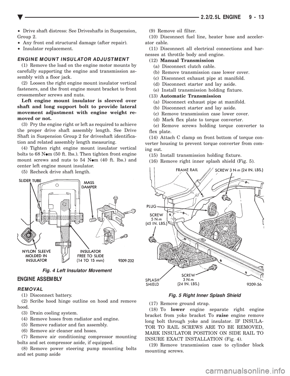
(16) Remove right inner splash shield (Fig. 5).
(17) Remove ground strap.
(18) To lowerengine separate right engine
bracket from yoke bracket To raiseengine remove
long bolt through yoke and insulator. IF INSULA-
TOR TO RAIL SCREWS ARE TO BE REMOVED,
MARK INSULATOR POSITION ON SIDE RAIL TO
INSURE EXACT INSTALLATION (Fig. 4). (19) Remove transmission case to cylinder block
mounting screws.Fig. 5 Right Inner Splash Shield
Fig. 4 Left Insulator Movement
Ä 2.2/2.5L ENGINE 9 - 13
Page 1592 of 2438
valve spring retainer locks to become dislocated
when depressing the valve spring. Check and make
sure the locks are in their proper location. (3) Install valve cover as previously outlined in
this section.
VALVE SPRINGS AND VALVE STEM SEALS
REMOVAL
(1) Remove rocker arms as previously outlined in
this section. (2) Rotate crankshaft until piston is at TDC on
compression. (3) With air hose attached to adapter tool installed
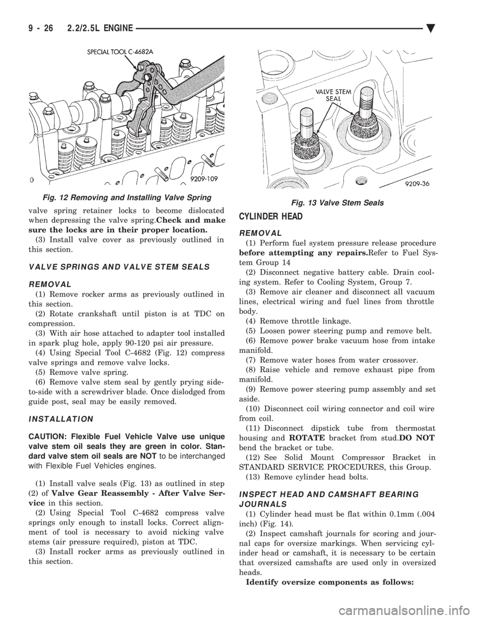
in spark plug hole, apply 90-120 psi air pressure. (4) Using Special Tool C-4682 (Fig. 12) compress
valve springs and remove valve locks. (5) Remove valve spring.
(6) Remove valve stem seal by gently prying side-
to-side with a screwdriver blade. Once dislodged from
guide post, seal may be easily removed.
INSTALLATION
CAUTION: Flexible Fuel Vehicle Valve use unique
valve stem oil seals they are green in color. Stan-
dard valve stem oil seals are NOT to be interchanged
with Flexible Fuel Vehicles engines.
(1) Install valve seals (Fig. 13) as outlined in step
(2) of Valve Gear Reassembly - After Valve Ser-
vice in this section.
(2) Using Special Tool C-4682 compress valve
springs only enough to install locks. Correct align-
ment of tool is necessary to avoid nicking valve
stems (air pressure required), piston at TDC. (3) Install rocker arms as previously outlined in
this section.
CYLINDER HEAD
REMOVAL
(1) Perform fuel system pressure release procedure
before attempting any repairs. Refer to Fuel Sys-
tem Group 14 (2) Disconnect negative battery cable. Drain cool-
ing system. Refer to Cooling System, Group 7. (3) Remove air cleaner and disconnect all vacuum
lines, electrical wiring and fuel lines from throttle
body. (4) Remove throttle linkage.
(5) Loosen power steering pump and remove belt.
(6) Remove power brake vacuum hose from intake
manifold. (7) Remove water hoses from water crossover.
(8) Raise vehicle and remove exhaust pipe from
manifold. (9) Remove power steering pump assembly and set
aside. (10) Disconnect coil wiring connector and coil wire
from coil. (11) Disconnect dipstick tube from thermostat
housing and ROTATEbracket from stud. DO NOT
bend the bracket or tube. (12) See Solid Mount Compressor Bracket in
STANDARD SERVICE PROCEDURES, this Group. (13) Remove cylinder head bolts.
INSPECT HEAD AND CAMSHAFT BEARINGJOURNALS
(1) Cylinder head must be flat within 0.1mm (.004
inch) (Fig. 14). (2) Inspect camshaft journals for scoring and jour-
nal caps for oversize markings. When servicing cyl-
inder head or camshaft, it is necessary to be certain
that oversized camshafts are used only in oversized
heads. Identify oversize components as follows:
Fig. 12 Removing and Installing Valve SpringFig. 13 Valve Stem Seals
9 - 26 2.2/2.5L ENGINE Ä
Page 1624 of 2438
OIL PAN
A formed steel oil pan provides lower engine pro-
tection as well as serving as the engine oil reservoir
(Fig. 1). Pan side flanges to block are sealed with
gaskets. The oil pickup tube for some 2.2L engines
have a circular strainer and cover. The 2.5L engine
pickup is also unsupported and the lower end has a
box type strainer (Fig. 4).
PRESSURE LUBRICATION
Oil drawn up through the pickup tube is pressur-
ized by the pump and routed through the full flow
filter to the main oil gallery running the length of
the cylinder block (Fig. 2). Modified oil pickup, pump
and check valve provide increased oil flow to the
main oil gallery.
MAIN/ROD BEARINGS
A diagonal hole in each bulkhead feeds oil to each
main bearing. Drilled passages within the crankshaft
route oil from main bearing journals to crankpin
journals.
ACCESSORY SHAFT
Two separate holes supply the accessory shaft for
the N/A engines. For Turbo III engines there is a slot
in the rear shaft bushing that squirts oil onto the
oil pump drive gears (Fig. 2).
BALANCE SHAFTS
The engine balance shafts are lubricated by an ad-
ditional hole that interconnects a passage in one leg
of the balance shaft carrier to route oil down to the
carrier oil gallery. This gallery directly supplies the
balance shafts front bearings and internal machined
passages in the shafts routes oil from front to rear
shaft bearing journals.
TURBOCHARGER (WHERE EQUIPPED)
If turbocharger equipped, pressurized oil from the
main gallery to sending unit hex fitting is piped from
the fitting to the turbocharger bearing housing.
From the housing a hose and tube connection to a
machined hole in the block provides drainback.
CAMSHAFT/HYDRAULIC LIFTERS
A vertical hole at the number five bulkhead routes
pressurized oil through a restrictor up past a cylinder
head bolt to an oil gallery running the length of the
cylinder head. For 2.2/2.5L and 2.5L FFV engines
hydraulic adjusters are supplied directly from this
gallery while diagonal holes supply oil to the cam-
shaft journals. The camshaft journals are partially
slotted to allow a predetermined amount of pressur-
ized oil to pass into the bearing cap cavities with
small holes directed to spray lubricate the camshaft
lobes. For Turbo III engines oil is supplied thru oil
galleries in the head to the camshafts and rocker arm shafts which feed oil to the lash adjusters. Oil is
feed thru the rocker arms to lubricate the rollers and
the camshaft lobes.
SPLASH LUBRICATION
Oil returning to the pan from pressurized compo-
nents supplies lubrication to the valve stems. Cylinder
bores and wrist pins are splash lubricated from di-
rected holes in the connecting rods.
OIL PAN
REMOVAL
(1) Drain engine oil and remove oil pan.
(2) Clean oil pan and all gasket surfaces.
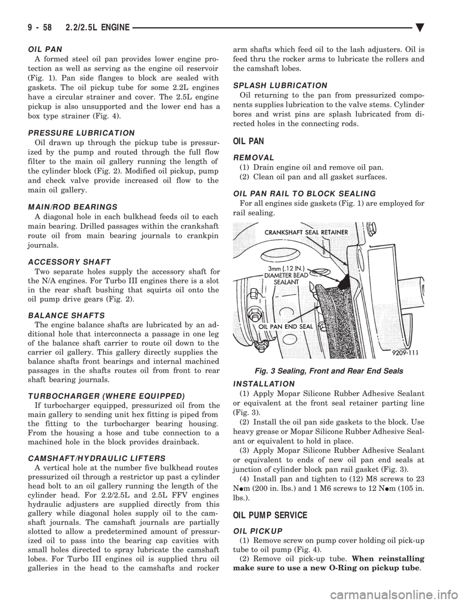
OIL PAN RAIL TO BLOCK SEALING
For all engines side gaskets (Fig. 1) are employed for
rail sealing.
INSTALLATION
(1) Apply Mopar Silicone Rubber Adhesive Sealant
or equivalent at the front seal retainer parting line
(Fig. 3). (2) Install the oil pan side gaskets to the block. Use
heavy grease or Mopar Silicone Rubber Adhesive Seal-
ant or equivalent to hold in place. (3) Apply Mopar Silicone Rubber Adhesive Sealant
or equivalent to ends of new oil pan end seals at
junction of cylinder block pan rail gasket (Fig. 3). (4) Install pan and tighten to (12) M8 screws to 23
N Im (200 in. lbs.) and 1 M6 screws to 12 N Im (105 in.
lbs.).
OIL PUMP SERVICE
OIL PICKUP
(1) Remove screw on pump cover holding oil pick-up
tube to oil pump (Fig. 4). (2) Remove oil pick-up tube. When reinstalling
make sure to use a new O-Ring on pickup tube .
Fig. 3 Sealing, Front and Rear End Seals
9 - 58 2.2/2.5L ENGINE Ä
Page 1635 of 2438
LEFT SIDE MOUNT
(1) Raise vehicle on hoist and remove left front
wheel. (2) Remove inter splash shield.
(3) Support the transmission with a transmission
jack. (4) Remove the insulator thru bolt from the mount.
(5) Remove the transmission mount fasteners and
remove mount. (6) Reverse removal procedure for installation. En-
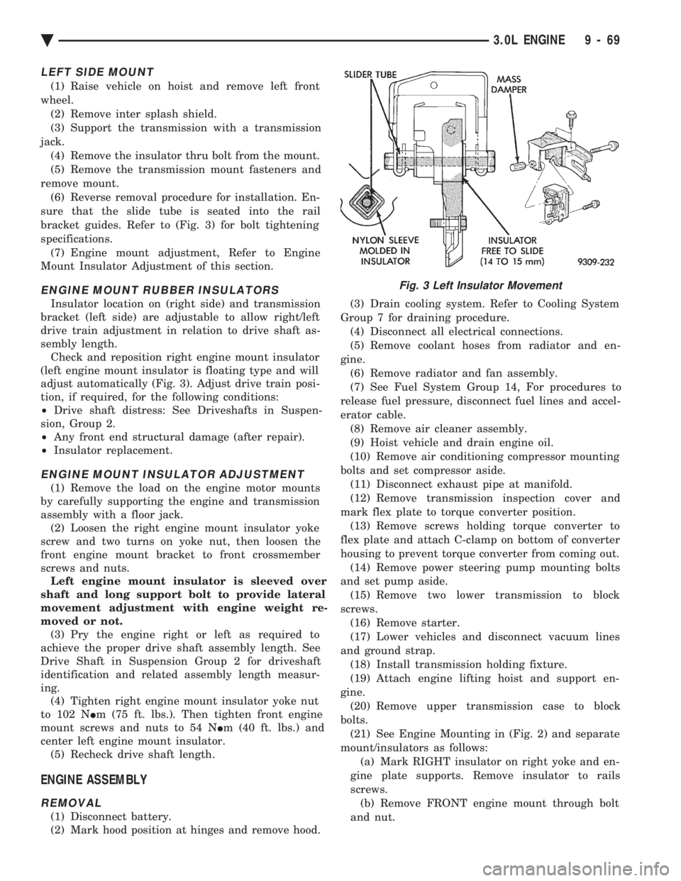
sure that the slide tube is seated into the rail
bracket guides. Refer to (Fig. 3) for bolt tightening
specifications. (7) Engine mount adjustment, Refer to Engine
Mount Insulator Adjustment of this section.
ENGINE MOUNT RUBBER INSULATORS
Insulator location on (right side) and transmission
bracket (left side) are adjustable to allow right/left
drive train adjustment in relation to drive shaft as-
sembly length. Check and reposition right engine mount insulator
(left engine mount insulator is floating type and will
adjust automatically (Fig. 3). Adjust drive train posi-
tion, if required, for the following conditions:
² Drive shaft distress: See Driveshafts in Suspen-
sion, Group 2.
² Any front end structural damage (after repair).
² Insulator replacement.
ENGINE MOUNT INSULATOR ADJUSTMENT
(1) Remove the load on the engine motor mounts
by carefully supporting the engine and transmission
assembly with a floor jack. (2) Loosen the right engine mount insulator yoke
screw and two turns on yoke nut, then loosen the
front engine mount bracket to front crossmember
screws and nuts. Left engine mount insulator is sleeved over
shaft and long support bolt to provide lateral
movement adjustment with engine weight re-
moved or not. (3) Pry the engine right or left as required to
achieve the proper drive shaft assembly length. See
Drive Shaft in Suspension Group 2 for driveshaft
identification and related assembly length measur-
ing. (4) Tighten right engine mount insulator yoke nut
to 102 N Im (75 ft. lbs.). Then tighten front engine
mount screws and nuts to 54 N Im (40 ft. lbs.) and
center left engine mount insulator. (5) Recheck drive shaft length.
ENGINE ASSEMBLY
REMOVAL
(1) Disconnect battery.
(2) Mark hood position at hinges and remove hood. (3) Drain cooling system. Refer to Cooling System
Group 7 for draining procedure. (4) Disconnect all electrical connections.
(5) Remove coolant hoses from radiator and en-
gine. (6) Remove radiator and fan assembly.
(7) See Fuel System Group 14, For procedures to
release fuel pressure, disconnect fuel lines and accel-
erator cable. (8) Remove air cleaner assembly.
(9) Hoist vehicle and drain engine oil.
(10) Remove air conditioning compressor mounting
bolts and set compressor aside. (11) Disconnect exhaust pipe at manifold.
(12) Remove transmission inspection cover and
mark flex plate to torque converter position. (13) Remove screws holding torque converter to
flex plate and attach C-clamp on bottom of converter
housing to prevent torque converter from coming out. (14) Remove power steering pump mounting bolts
and set pump aside. (15) Remove two lower transmission to block
screws. (16) Remove starter.
(17) Lower vehicles and disconnect vacuum lines
and ground strap. (18) Install transmission holding fixture.
(19) Attach engine lifting hoist and support en-
gine. (20) Remove upper transmission case to block
bolts. (21) See Engine Mounting in (Fig. 2) and separate
mount/insulators as follows: (a) Mark RIGHT insulator on right yoke and en-
gine plate supports. Remove insulator to rails
screws. (b) Remove FRONT engine mount through bolt
and nut.
Fig. 3 Left Insulator Movement
Ä 3.0L ENGINE 9 - 69