1993 CHEVROLET PLYMOUTH ACCLAIM drain bolt
[x] Cancel search: drain boltPage 2053 of 2438
FLUID LEVEL AND CONDITION
The transmission and differential sump have a
common oil sump with a communicating opening
between the two. The torque converter fills in both the PPark and N
Neutral positions. Place the selector lever in PPark to
check the fluid level. The engine should be running
at idle speed for at least one minute, with the
vehicle on level ground. This will assure com-
plete oil level stabilization between differential
and transmission. The fluid should be at normal
operating temperature (approximately 82 C. or 180 F.).
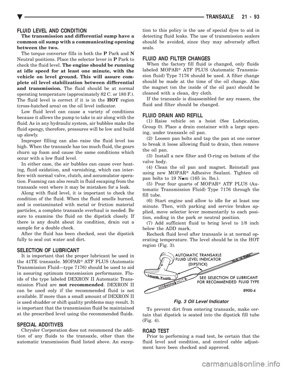
The fluid level is correct if it is in the HOTregion
(cross-hatched area) on the oil level indicator. Low fluid level can cause a variety of conditions
because it allows the pump to take in air along with the
fluid. As in any hydraulic system, air bubbles make the
fluid spongy, therefore, pressures will be low and build
up slowly. Improper filling can also raise the fluid level too
high. When the transaxle has too much fluid, the gears
churn up foam and cause the same conditions which
occur with a low fluid level. In either case, the air bubbles can cause over heat-
ing, fluid oxidation, and varnishing, which can inter-
fere with normal valve, clutch, and accumulator opera-
tion. Foaming can also result in fluid escaping from the
transaxle vent where it may be mistaken for a leak. Along with fluid level, it is important to check the
condition of the fluid. When the fluid smells burned,
and is contaminated with metal or friction material
particles, a complete transaxle overhaul is needed. Be
sure to examine the fluid on the dipstick closely. If
there is any doubt about its condition, drain out a
sample for a double check. After the fluid has been checked, seat the dipstick
fully to seal out water and dirt.
SELECTION OF LUBRICANT
It is important that the proper lubricant be used in
the 41TE transaxle. MOPAR tATF PLUS (Automatic
Transmission FluidÐtype 7176) should be used to aid
in assuring optimum transmission performance. Flu-
ids of the type labeled DEXRON II Automatic Trans-
mission Fluid are not recommended . DEXRON II
can be used only if the recommended fluid is not
available. If more than a small amount of DEXRON II
is used shudder or shift quality problems may result. It
is important that the transmission fluid be maintained
at the prescribed level using the recommended fluids.
SPECIAL ADDITIVES
Chrysler Corporation does not recommend the addi-
tion of any fluids to the transaxle, other than the
automatic transmission fluid listed above. An excep- tion to this policy is the use of special dyes to aid in
detecting fluid leaks. The use of transmission sealers
should be avoided, since they may adversely affect
seals.
FLUID AND FILTER CHANGES
When the factory fill fluid is changed, only fluids
labeled MOPAR tATF PLUS (Automatic Transmis-
sion fluid) Type 7176 should be used. A filter change
should be made at the time of the oil change. Also
the magnet (on the inside of the oil pan) should be
cleaned with a clean, dry cloth. If the transaxle is disassembled for any reason, the
fluid and filter should be changed.
FLUID DRAIN AND REFILL
(1) Raise vehicle on a hoist (See Lubrication,
Group 0). Place a drain container with a large open-
ing, under transaxle oil pan. (2) Loosen pan bolts and tap the pan at one corner
to break it loose allowing fluid to drain, then remove
the oil pan. (3) Install a new filter and O-ring on bottom of the
valve body. (4) Clean the oil pan and magnet. Reinstall pan
using new MOPAR tAdhesive Sealant. Tighten oil
pan bolts to 19 N Im (165 in. lbs.).
(5) Pour four quarts of MOPAR tATF PLUS (Au-
tomatic Transmission Fluid) Type 7176 through the
fill tube. (6) Start engine and allow to idle for at least one
minute. Then, with parking and service brakes ap-
plied, move selector lever momentarily to each posi-
tion, ending in the park or neutral position. (7) Add sufficient fluid to bring level to 1/8 inch
below the ADD mark. Recheck fluid level after transaxle is at normal op-
erating temperature. The level should be in the HOT
region (Fig. 3).
To prevent dirt from entering transaxle, make cer-
tain that dipstick is seated into the dipstick fill tube
(Fig. 4).
ROAD TEST
Prior to performing a road test, be certain that the
fluid level and condition, and control cable adjust-
ment have been checked and approved.
Fig. 3 Oil Level Indicator
Ä TRANSAXLE 21 - 93
Page 2057 of 2438
first separator plate and watch carefully for the pis-
ton to move forward. The piston should return to its
original position after the air pressure is removed.
UNDERDRIVE CLUTCH
Because this clutch piston cannot be seen, its oper-
ation is checked by function. Air pressure is applied
to the low/reverse and the 2/4 clutches. This locks
the output shaft. Use a piece of rubber hose wrapped
around the input shaft and a pair of clamp-on pliers
to turn the input shaft. Next apply air pressure to
the underdrive clutch. The input shaft should not ro-
tate with hand torque. Release the air pressure and
confirm that the input shaft will rotate.
FLUID LEAKAGE-TORQUE CONVERTER HOUSING
AREA
(1) Check for source of leakage.
Since fluid leakage at or around the torque con-
verter area may originate from an engine oil leak,
the area should be examined closely. Factory fill
fluid is dyed red and, therefore, can be distinguished
from engine oil. (2) Prior to removing the transaxle, perform the
following checks: When leakage is determined to originate from the
transaxle, check fluid level prior to removal of the
transaxle and torque converter. High oil level can result in oil leakage out the vent
in the manual shaft. If the fluid level is high, adjust
to proper level. After performing this operation, inspect for leak-
age. If a leak persists, perform the following opera-
tion on the vehicle to determine if it is the torque
converter or transaxle that is leaking.
LEAKAGE TEST PROBE
(1) Remove torque converter housing dust shield.
(2) Clean the inside of torque converter housing
(lower area) as dry as possible. A solvent spray fol-
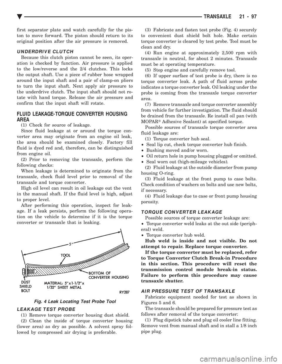
lowed by compressed air drying is preferable. (3) Fabricate and fasten test probe (Fig. 4) securely
to convenient dust shield bolt hole. Make certain
torque converter is cleared by test probe. Tool must be
clean and dry. (4) Run engine at approximately 2,500 rpm with
transaxle in neutral, for about 2 minutes. Transaxle
must be at operating temperature. (5) Stop engine and carefully remove tool.
(6) If upper surface of test probe is dry, there is no
torque converter leak. A path of fluid across probe
indicates a torque converter leak. Oil leaking under the
probe is coming from the transaxle torque converter
area. (7) Remove transaxle and torque converter assembly
from vehicle for further investigation. The fluid should
be drained from the transaxle. Re install oil pan (with
MOPAR tAdhesive Sealant) at specified torque.
Possible sources of transaxle torque converter area
fluid leakage are: (1) Torque converter hub seal.
² Seal lip cut, check torque converter hub finish.
² Bushing moved and/or worn.
² Oil return hole in pump housing plugged or omitted.
² Seal worn out (high-mileage vehicles).
(2) Fluid leakage at the outside diameter from pump
housing O-ring. (3) Fluid leakage at the front pump to case bolts.
Check condition of washers on bolts and use new bolts,
if necessary. (4) Fluid leakage due to case or front pump housing
porosity.
TORQUE CONVERTER LEAKAGE
Possible sources of torque converter leakage are:
² Torque converter weld leaks at the out side (periph-
eral) weld.
² Torque converter hub weld.
Hub weld is inside and not visible. Do not
attempt to repair. Replace torque converter. If the torque converter must be replaced, refer
to Torque Converter Clutch Break-in Procedure
in this section. This procedure will reset the
transmission control module break-in status.
Failure to perform this procedure may cause
transaxle shutter.
AIR PRESSURE TEST OF TRANSAXLE
Fabricate equipment needed for test as shown in
Figures 5 and 6. The transaxle should be prepared for pressure test as
follows after removal of the torque converter: (1) Plug dipstick tube and plug oil cooler line fitting.
Remove vent from manual shaft and in stall a 1/8 inch
pipe plug.Fig. 4 Leak Locating Test Probe Tool
Ä TRANSAXLE 21 - 97
Page 2059 of 2438
CAUTION: If the vehicle is equipped with two oil
coolers (one in the radiator tank, one in front of the
radiator) they must be flushed separately. Do not
attempt to flush both coolers at one time. (1) Disconnect the cooler lines at the transmission.
(2) Using a hand suction gun filled with mineral
spirits, reverse flush the cooler. Force mineral spirits
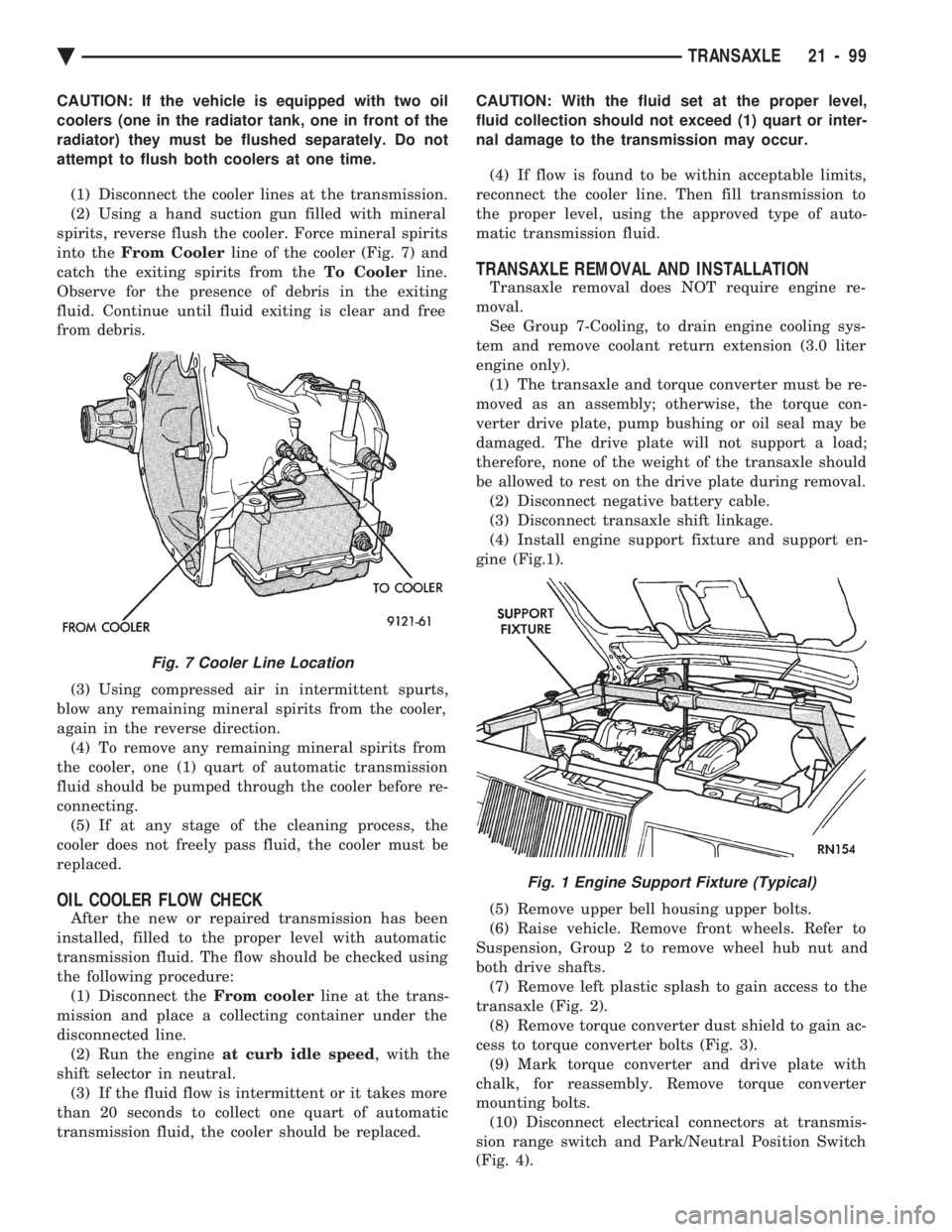
into the From Cooler line of the cooler (Fig. 7) and
catch the exiting spirits from the To Coolerline.
Observe for the presence of debris in the exiting
fluid. Continue until fluid exiting is clear and free
from debris.
(3) Using compressed air in intermittent spurts,
blow any remaining mineral spirits from the cooler,
again in the reverse direction. (4) To remove any remaining mineral spirits from
the cooler, one (1) quart of automatic transmission
fluid should be pumped through the cooler before re-
connecting. (5) If at any stage of the cleaning process, the
cooler does not freely pass fluid, the cooler must be
replaced.
OIL COOLER FLOW CHECK
After the new or repaired transmission has been
installed, filled to the proper level with automatic
transmission fluid. The flow should be checked using
the following procedure: (1) Disconnect the From coolerline at the trans-
mission and place a collecting container under the
disconnected line. (2) Run the engine at curb idle speed , with the
shift selector in neutral. (3) If the fluid flow is intermittent or it takes more
than 20 seconds to collect one quart of automatic
transmission fluid, the cooler should be replaced. CAUTION: With the fluid set at the proper level,
fluid collection should not exceed (1) quart or inter-
nal damage to the transmission may occur.
(4) If flow is found to be within acceptable limits,
reconnect the cooler line. Then fill transmission to
the proper level, using the approved type of auto-
matic transmission fluid.
TRANSAXLE REMOVAL AND INSTALLATION
Transaxle removal does NOT require engine re-
moval. See Group 7-Cooling, to drain engine cooling sys-
tem and remove coolant return extension (3.0 liter
engine only). (1) The transaxle and torque converter must be re-
moved as an assembly; otherwise, the torque con-
verter drive plate, pump bushing or oil seal may be
damaged. The drive plate will not support a load;
therefore, none of the weight of the transaxle should
be allowed to rest on the drive plate during removal. (2) Disconnect negative battery cable.
(3) Disconnect transaxle shift linkage.
(4) Install engine support fixture and support en-
gine (Fig.1).
(5) Remove upper bell housing upper bolts.
(6) Raise vehicle. Remove front wheels. Refer to
Suspension, Group 2 to remove wheel hub nut and
both drive shafts. (7) Remove left plastic splash to gain access to the
transaxle (Fig. 2). (8) Remove torque converter dust shield to gain ac-
cess to torque converter bolts (Fig. 3). (9) Mark torque converter and drive plate with
chalk, for reassembly. Remove torque converter
mounting bolts. (10) Disconnect electrical connectors at transmis-
sion range switch and Park/Neutral Position Switch
(Fig. 4).
Fig. 7 Cooler Line Location
Fig. 1 Engine Support Fixture (Typical)
Ä TRANSAXLE 21 - 99
Page 2162 of 2438
POWER SUNROOF INDEX
page page
Adjustment Bracket ........................ 7
Drain Channel ............................ 7
Drive Cable Locators ....................... 7
Drive Cables ............................. 8
General Information ........................ 6
Glass Panel ............................. 7 Glass Vertical Height Adjustment
.............. 6
Guide Assembly .......................... 8
Motor and Drive Gears ..................... 7
Sunshade ............................... 8
Wind Deflector ........................... 6
GENERAL INFORMATION
All sunroofs are equipped with drain tubes that are
located in the A, B or C-pillars. The drain tubes
must be kept open to prevent water from entering
the passenger compartment.
LUBRICATION
(1) Lubricate cables with Lubriplate or equivalent
when cables are replaced. (2) Periodically clean dirt from guide rail covers.
DRAIN TUBES
² Inspect the drain holes, located in the trough
around the sunroof opening to verify they are clear.
Inspection should be performed at least once a year
or when problems are suspected. If drain hose or
tubes are plugged, use compressed air or blunt flexi-
ble wire to clear them. If tubes cannot be cleared,
they must be repaired.
² The lower ends of the rear drain tubes are located
in the rear quarter panel drop wells. To clear rear
drain tubes, use compressed air or blunt flexible wire
from the lower ends of the tubes.
GLASS VERTICAL HEIGHT ADJUSTMENT
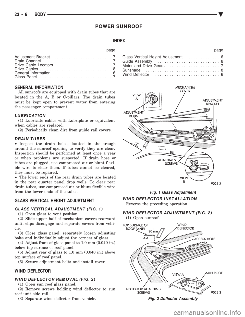
GLASS VERTICAL ADJUSTMENT (FIG. 1)
(1) Open glass to vent position.
(2) Slide upper half of mechanism covers rearward
until clips disengage and separate covers from vehi-
cle. (3) Close glass panel, separately loosen adjusting
bolts and individually adjust the corners of glass. (4) Adjust front of glass panel to 1.0 mm (0.040 in.)
below top surface of roof panel. (5) Adjust rear of glass to 1.0 mm (0.040 in.) above
top surface of roof panel. (6) Secure adjustment bolts and install cover.
WIND DEFLECTOR
WIND DEFLECTOR REMOVAL (FIG. 2)
(1) Open sun roof glass panel.
(2) Remove screws holding wind deflector to sun
roof unit side rail. (3) Separate wind deflector from vehicle.
WIND DEFLECTOR INSTALLATION
Reverse the preceding operation.
WIND DEFLECTOR ADJUSTMENT (FIG. 2)
(1) Open sunroof.
Fig. 1 Glass Adjustment
Fig. 2 Deflector Assembly
23 - 6 BODY Ä
Page 2163 of 2438
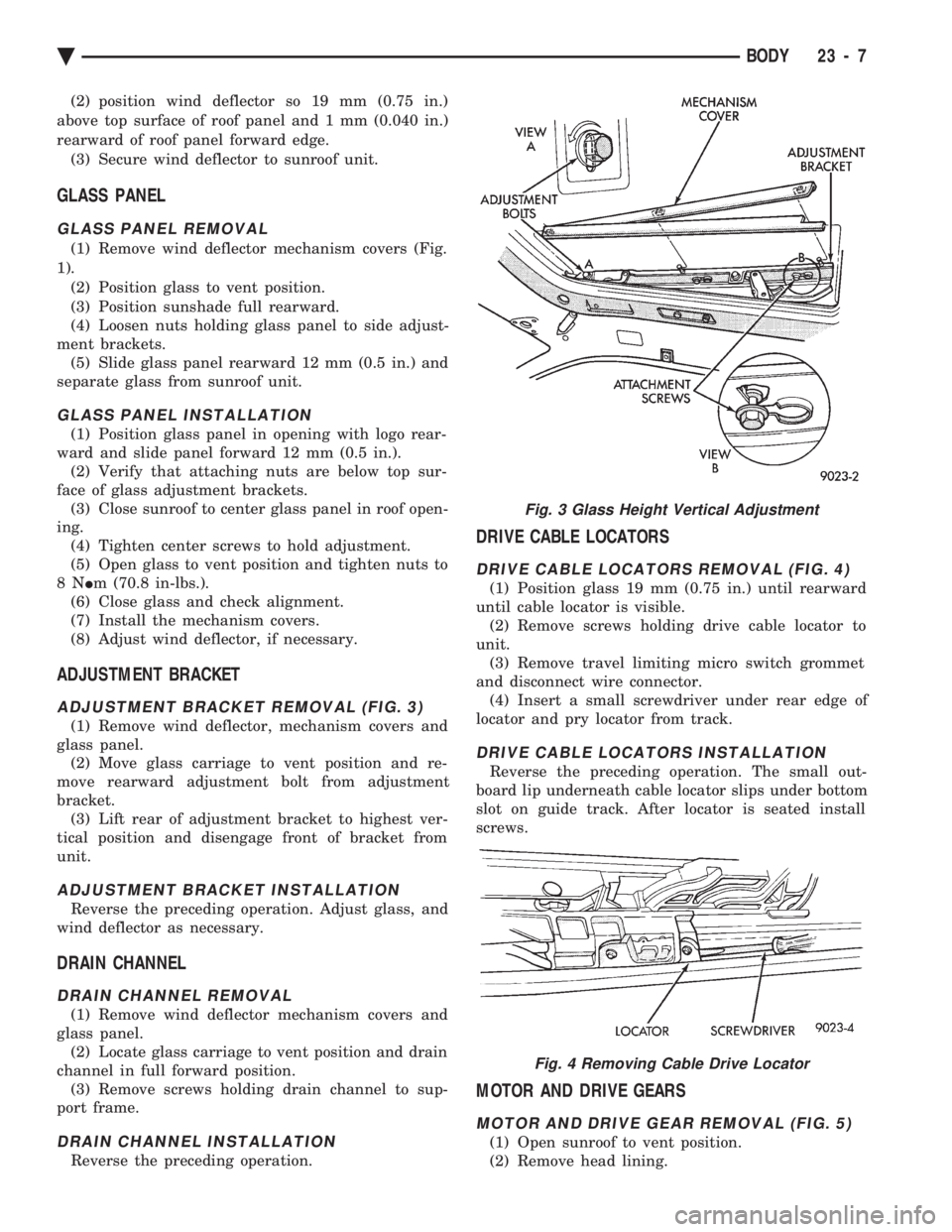
(2) position wind deflector so 19 mm (0.75 in.)
above top surface of roof panel and 1 mm (0.040 in.)
rearward of roof panel forward edge. (3) Secure wind deflector to sunroof unit.
GLASS PANEL
GLASS PANEL REMOVAL
(1) Remove wind deflector mechanism covers (Fig.
1). (2) Position glass to vent position.
(3) Position sunshade full rearward.
(4) Loosen nuts holding glass panel to side adjust-
ment brackets. (5) Slide glass panel rearward 12 mm (0.5 in.) and
separate glass from sunroof unit.
GLASS PANEL INSTALLATION
(1) Position glass panel in opening with logo rear-
ward and slide panel forward 12 mm (0.5 in.). (2) Verify that attaching nuts are below top sur-
face of glass adjustment brackets. (3) Close sunroof to center glass panel in roof open-
ing. (4) Tighten center screws to hold adjustment.
(5) Open glass to vent position and tighten nuts to
8N Im (70.8 in-lbs.).
(6) Close glass and check alignment.
(7) Install the mechanism covers.
(8) Adjust wind deflector, if necessary.
ADJUSTMENT BRACKET
ADJUSTMENT BRACKET REMOVAL (FIG. 3)
(1) Remove wind deflector, mechanism covers and
glass panel. (2) Move glass carriage to vent position and re-
move rearward adjustment bolt from adjustment
bracket. (3) Lift rear of adjustment bracket to highest ver-
tical position and disengage front of bracket from
unit.
ADJUSTMENT BRACKET INSTALLATION
Reverse the preceding operation. Adjust glass, and
wind deflector as necessary.
DRAIN CHANNEL
DRAIN CHANNEL REMOVAL
(1) Remove wind deflector mechanism covers and
glass panel. (2) Locate glass carriage to vent position and drain
channel in full forward position. (3) Remove screws holding drain channel to sup-
port frame.
DRAIN CHANNEL INSTALLATION
Reverse the preceding operation.
DRIVE CABLE LOCATORS
DRIVE CABLE LOCATORS REMOVAL (FIG. 4)
(1) Position glass 19 mm (0.75 in.) until rearward
until cable locator is visible. (2) Remove screws holding drive cable locator to
unit. (3) Remove travel limiting micro switch grommet
and disconnect wire connector. (4) Insert a small screwdriver under rear edge of
locator and pry locator from track.
DRIVE CABLE LOCATORS INSTALLATION
Reverse the preceding operation. The small out-
board lip underneath cable locator slips under bottom
slot on guide track. After locator is seated install
screws.
MOTOR AND DRIVE GEARS
MOTOR AND DRIVE GEAR REMOVAL (FIG. 5)
(1) Open sunroof to vent position.
(2) Remove head lining.
Fig. 3 Glass Height Vertical Adjustment
Fig. 4 Removing Cable Drive Locator
Ä BODY 23 - 7
Page 2164 of 2438
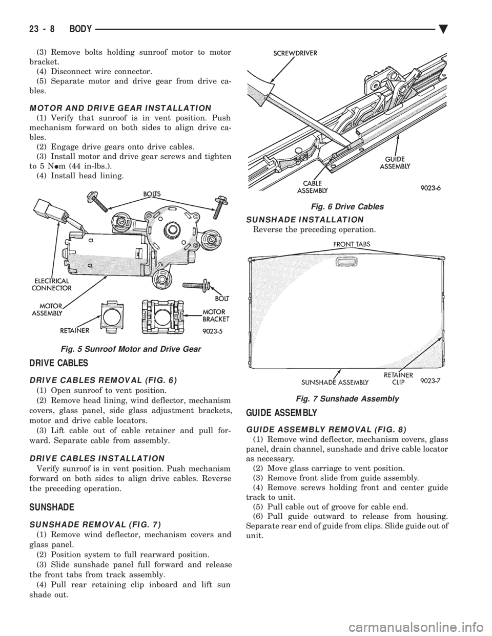
(3) Remove bolts holding sunroof motor to motor
bracket. (4) Disconnect wire connector.
(5) Separate motor and drive gear from drive ca-
bles.
MOTOR AND DRIVE GEAR INSTALLATION
(1) Verify that sunroof is in vent position. Push
mechanism forward on both sides to align drive ca-
bles. (2) Engage drive gears onto drive cables.
(3) Install motor and drive gear screws and tighten
to5N Im (44 in-lbs.).
(4) Install head lining.
DRIVE CABLES
DRIVE CABLES REMOVAL (FIG. 6)
(1) Open sunroof to vent position.
(2) Remove head lining, wind deflector, mechanism
covers, glass panel, side glass adjustment brackets,
motor and drive cable locators. (3) Lift cable out of cable retainer and pull for-
ward. Separate cable from assembly.
DRIVE CABLES INSTALLATION
Verify sunroof is in vent position. Push mechanism
forward on both sides to align drive cables. Reverse
the preceding operation.
SUNSHADE
SUNSHADE REMOVAL (FIG. 7)
(1) Remove wind deflector, mechanism covers and
glass panel. (2) Position system to full rearward position.
(3) Slide sunshade panel full forward and release
the front tabs from track assembly. (4) Pull rear retaining clip inboard and lift sun
shade out.
SUNSHADE INSTALLATION
Reverse the preceding operation.
GUIDE ASSEMBLY
GUIDE ASSEMBLY REMOVAL (FIG. 8)
(1) Remove wind deflector, mechanism covers, glass
panel, drain channel, sunshade and drive cable locator
as necessary. (2) Move glass carriage to vent position.
(3) Remove front slide from guide assembly.
(4) Remove screws holding front and center guide
track to unit. (5) Pull cable out of groove for cable end.
(6) Pull guide outward to release from housing.
Separate rear end of guide from clips. Slide guide out of
unit.
Fig. 5 Sunroof Motor and Drive Gear
Fig. 6 Drive Cables
Fig. 7 Sunshade Assembly
23 - 8 BODY Ä
Page 2167 of 2438
AA-VEHICLE BODY COMPONENT SERVICE INDEX
page page
A-Pillar and Roof Rail Mouldings ............. 25
B-Pillar Trim Panel ....................... 25
Body Side Moulding and Applique ............ 24
Cowl Cover ............................. 13
Cowl Panel Trim and Scuff Plates ............ 25
Door Opening Weatherstrips ................ 24
Floor Carpet ............................ 30
Front Center Console ..................... 29
Front Door and Hinge ..................... 15
Front Door Belt Moulding and Weatherstrip ..... 17
Front Door Glass ........................ 17
Front Door Glass Channel and Run Weatherstrip . 18
Front Door Glass Run Lower Channel ......... 18
Front Door Latch ......................... 16
Front Door Side View Mirror ................ 17
Front Door Silencer and Water Shield ......... 15
Front Door Trim Panel .................... 14
Front Door Window Regulator/Manual ......... 18
Front Door Window Regulator/Power .......... 19
Front End Splash Shields .................. 13
Front Fender ............................ 14
Front Power Door Lock Actuator ............. 19
Front Seat Belts ......................... 27
Front Seats ............................. 28
Fuel Fill Door ........................... 36
Grille .................................. 11
Head Lining ............................. 30
Hood and Hinges ........................ 11
Hood Latch and Release Cable .............. 12
Outside Front Door Latch Release Handle ..... 16
Outside Rear Door Latch Release Handle ...... 21 Overhead Console
........................ 30
Quarter Extension Trim Panel ............... 27
Quarter Trim Panel ....................... 27
Rear Deck Filler Panel .................... 31
Rear Door and Hinge ..................... 20
Rear Door Belt Moulding and Weatherstrip ..... 22
Rear Door Glass ......................... 22
Rear Door Glass Run Weatherstrip ........... 22
Rear Door Glass Stationary Glass Module ..... 23
Rear Door Latch ......................... 21
Rear Door Silencer and Water Shield ......... 20
Rear Door Trim Panel ..................... 20
Rear Door Window Regulator/Manual ......... 23
Rear Door Window Regulator/Power .......... 23
Rear Power Door Lock Actuator ............. 22
Rear Seat Belts .......................... 28
Rear Seats ............................. 28
Rear Shelf Trim Panel ..................... 27
Rear Window Glass ...................... 32
Sun Roof Air Deflector .................... 31
Sun Roof Drain Tubes .................... 31
Sun Roof Weatherstrip .................... 31
Trunk Lid .............................. 33
Trunk Lid Hinge ......................... 34
Trunk Lid Latch .......................... 34
Trunk Lid Lock .......................... 34
Trunk Lid Luggage Rack ................... 35
Trunk Lid Torsion Bar ..................... 34
Trunk Lining ............................ 35
Trunk Opening Weatherstrip ................ 35
Vinyl Roof Bonnet ........................ 31
GRILLE
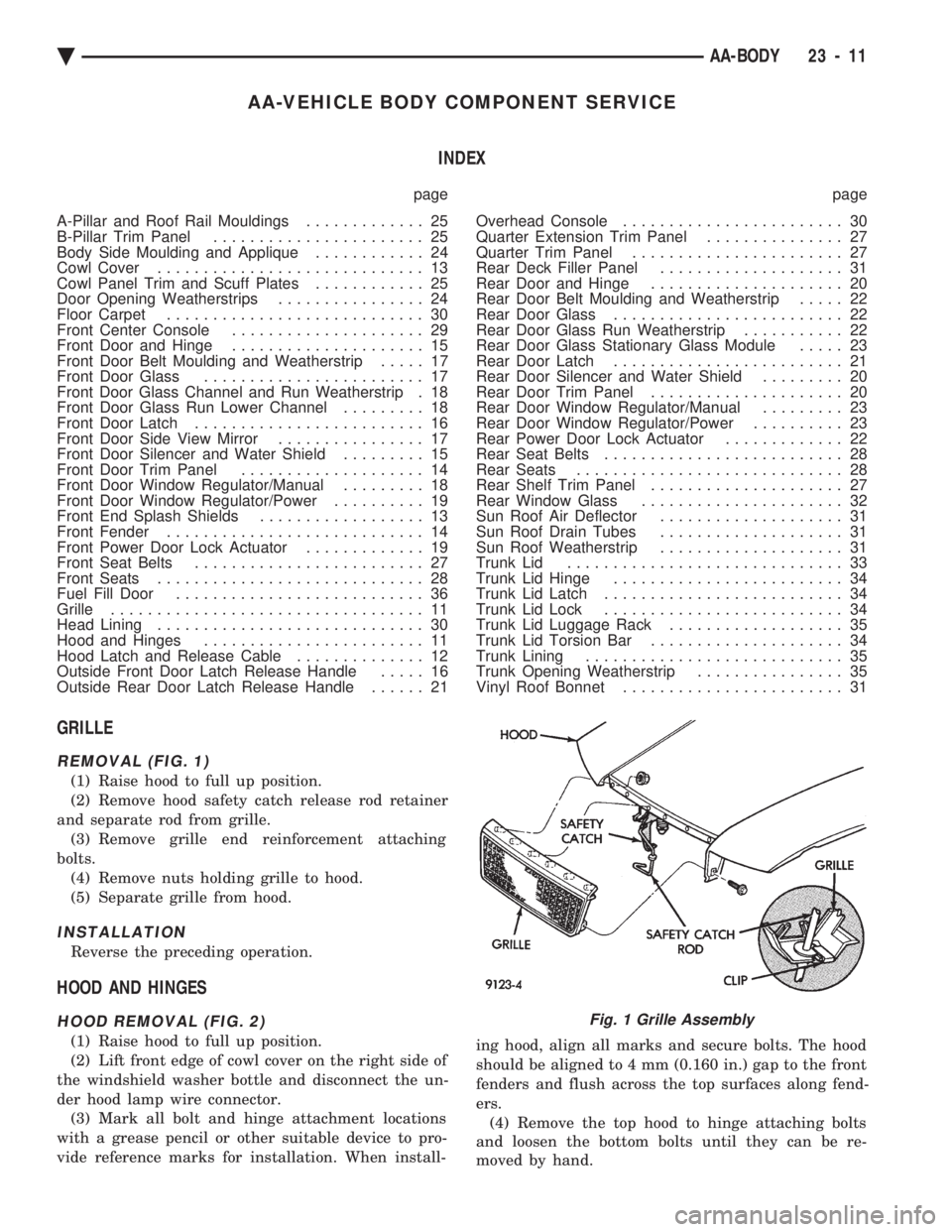
REMOVAL (FIG. 1)
(1) Raise hood to full up position.
(2) Remove hood safety catch release rod retainer
and separate rod from grille. (3) Remove grille end reinforcement attaching
bolts. (4) Remove nuts holding grille to hood.
(5) Separate grille from hood.
INSTALLATION
Reverse the preceding operation.
HOOD AND HINGES
HOOD REMOVAL (FIG. 2)
(1) Raise hood to full up position.
(2) Lift front edge of cowl cover on the right side of
the windshield washer bottle and disconnect the un-
der hood lamp wire connector. (3) Mark all bolt and hinge attachment locations
with a grease pencil or other suitable device to pro-
vide reference marks for installation. When install- ing hood, align all marks and secure bolts. The hood
should be aligned to 4 mm (0.160 in.) gap to the front
fenders and flush across the top surfaces along fend-
ers. (4) Remove the top hood to hinge attaching bolts
and loosen the bottom bolts until they can be re-
moved by hand.
Fig. 1 Grille Assembly
Ä AA-BODY 23 - 11
Page 2227 of 2438
AJ-VEHICLE BODY COMPONENT SERVICE INDEX
page page
A-Pillar and Roof Rail Mouldings ............. 77
Cowl Cover ............................. 73
Cowl Panel Trim and Scuff Plates ............ 77
Door Glass ............................. 76
Door Glass Lift Plate and Guide Post ......... 76
Door Latch ............................. 75
Door Trim Panel ......................... 74
Floor Carpet ............................ 80
Front Center Console ..................... 79
Front Door and Hinge ..................... 75
Front Door Silencer and Water Shield ......... 74
Front End Splash Shields .................. 73
Front Seat Belts ......................... 78
Front Seats ............................. 78
Fuel Fill Door ........................... 84
Glass Run WeatherstripÐAJ-21 Body ......... 76
Grille .................................. 71
Grille Header Molding ..................... 71
Grille Opening Panel ...................... 71
Head Lining ............................. 81
Hood and Hinges ........................ 72
Hood Latch and Release Cable .............. 72
Inside Latch Release Handle ................ 76 Lower Grille
............................. 71
Outside Door Latch Release Handle .......... 76
Overhead Console ........................ 80
Power Door Lock Actuator .................. 76
Quarter Extension Trim Panel ............... 77
Quarter Glass Module ..................... 85
Quarter Trim Panel ....................... 77
Rear Seat Belts .......................... 78
Rear Seats ............................. 79
Rear Shelf Trim Panel ..................... 78
Rear Window Glass ...................... 81
Sun Roof Air Deflector .................... 81
Sun Roof Drain Tubes .................... 81
Sun Roof Weatherstrip .................... 81
Trunk Lid .............................. 82
Trunk Lid and Fuel Fill Door Release Cables . . . 83
Trunk Lid Hinge ......................... 82
Trunk Lid Latch .......................... 83
Trunk Lid Lock .......................... 83
Trunk Lid Luggage Rack ................... 83
Trunk Lid Torsion Bar ..................... 83
Trunk Opening Weatherstrip ................ 83
Window Regulator ........................ 75
GRILLE
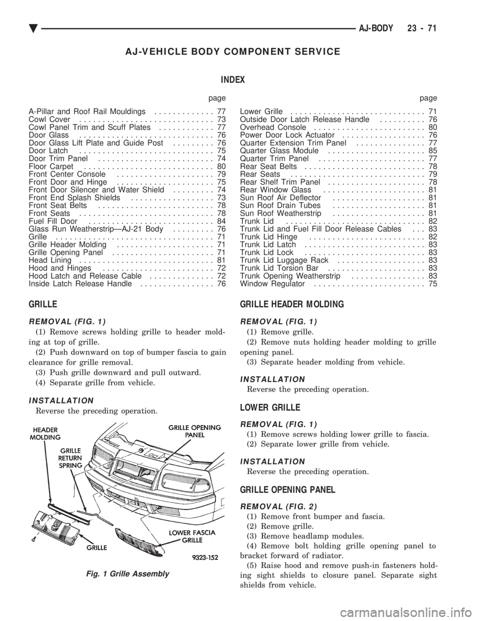
REMOVAL (FIG. 1)
(1) Remove screws holding grille to header mold-
ing at top of grille. (2) Push downward on top of bumper fascia to gain
clearance for grille removal. (3) Push grille downward and pull outward.
(4) Separate grille from vehicle.
INSTALLATION
Reverse the preceding operation.
GRILLE HEADER MOLDING
REMOVAL (FIG. 1)
(1) Remove grille.
(2) Remove nuts holding header molding to grille
opening panel. (3) Separate header molding from vehicle.
INSTALLATION
Reverse the preceding operation.
LOWER GRILLE
REMOVAL (FIG. 1)
(1) Remove screws holding lower grille to fascia.
(2) Separate lower grille from vehicle.
INSTALLATION
Reverse the preceding operation.
GRILLE OPENING PANEL
REMOVAL (FIG. 2)
(1) Remove front bumper and fascia.
(2) Remove grille.
(3) Remove headlamp modules.
(4) Remove bolt holding grille opening panel to
bracket forward of radiator. (5) Raise hood and remove push-in fasteners hold-
ing sight shields to closure panel. Separate sight
shields from vehicle.
Fig. 1 Grille Assembly
Ä AJ-BODY 23 - 71