1993 CHEVROLET PLYMOUTH ACCLAIM Ignition coil
[x] Cancel search: Ignition coilPage 483 of 2438

(2) With engine running, move test probe along
entire length of all cables (approximately 0 to 1/8
inch gap). If punctures or cracks are present there
will be a noticeable spark jump from the faulty area
to the probe. Cracked, leaking or faulty cables should
be replaced. Use the following procedure when removing the
high tension cable from the spark plug. First, remove
the cable from the retaining bracket. Then grasp the
terminal as close as possible to the spark plug. Ro-
tate the cover (boot) slightly and pull straight back.
Do not use pliers and do not pull the cable at an
angle. Doing so will damage the insulation, cable
terminal or the spark plug insulator. Wipe spark
plug insulator clean before reinstalling cable
and cover. Resistance cables are identified by the words Elec-
tronic Suppression .
Use an ohmmeter to check cables for opens, loose
terminals or high resistance. (a) Remove cable from spark plug.
(b) Remove cable from the coil tower.
(c) Connect the ohmmeter between spark plug
end terminal and the coil end terminal. Resistance
should be within tolerance shown in the cable re-
sistance chart. If resistance is not within tolerance,
replace cable assembly. Test all spark plug cables
in same manner.
SPARK PLUG SERVICE
When replacing the spark plug cables, route the ca-
bles correctly and secure them in the appropriate re-
tainers. Incorrectly routed cables can cause the radio
to reproduce ignition noise. It can also cause cross ig-
nition of the spark plugs or short circuit the cables to
ground.
SPARK PLUG REMOVAL
Always remove cables by grasping at boot, rotating
the boot 1/2 turn, and pulling straight back in a
steady motion. (1) Prior to removing the spark plug spray com-
pressed air around the spark plug hole and the area
around the spark plug. (2) Remove the spark plug using a quality socket
with a rubber or foam insert. (3) Inspect the spark plug condition. Refer to
Spark Plug Condition in this section.
SPARK PLUG GAP ADJUSTMENT
Check the spark plug gap with a gap gauge. If the
gap is not correct, adjust it by bending the ground
electrode (Fig. 6).
SPARK PLUG INSTALLATION
(1) To avoid cross threading, start the spark plug
into the cylinder head by hand. (2) Tighten spark plugs to 28 N Im (20 ft. lbs.)
torque. (3) Install spark plug cables over spark plugs.
IDLE RPM TEST
WARNING: BE SURE TO APPLY PARKING BRAKE
AND/OR BLOCK WHEELS BEFORE PERFORMING
ANY ENGINE RUNNING TESTS.
Engine idle set rpmshould be tested and recorded
as it is when the vehicle is first brought into shop
for testing. This will assist in diagnosing complaints
of engine stalling, creeping and hard shifting on ve-
hicles equipped with automatic transaxle. Refer to the
Throttle Body Minimum Airflow procedures in Group
14.
IGNITION TIMING PROCEDURE
Ignition timing cannot be changed or set on Turbo
III, 3.3L or 3.8L engines. For diagnostic information,
refer to the DRBII scan tool and the appropriate
Powertrain Diagnostics Procedures manual.
CABLE RESISTANCE CHART
Fig. 6 Setting Spark Plug GapÐTypical
Ä IGNITION SYSTEMS 8D - 41
Page 485 of 2438

CAMSHAFT POSITION SENSORÐ3.3L AND 3.8L
ENGINES
REMOVAL
(1) Disconnect camshaft position sensor electrical
connector from the wiring harness (Fig. 12). (2) Remove engine mount support bracket.
(3) Loosen camshaft position sensor retaining bolt
enough to allow slot in sensor to slide past the bolt. (4) Pull sensor up out of the chain case cover. Do not
pull on the sensor lead. There is an O-ring on the
sensor case. The O-ring may make removal difficult. A
light tap to top of sensor prior to removal may reduce
force needed for removal.
INSTALLATION
If installing the original sensor, clean off the
old spacer on the sensor face. A NEW SPACER
must be attached to the face before installation.
Inspect O-ring for damage, replace if necessary. If the
sensor is being replaced, confirm that the paper spacer is attached to the face and O-ring is posi-
tioned in groove of the new sensor (Fig. 13).
(1) Apply a couple drops of clean engine oil to the
O-ring prior to installation. Install sensor in the
chain case cover and push sensor down until contact
is made with the camshaft timing gear. While hold-
ing the sensor in this position, install and tighten
the retaining bolt 14 N Im (125 in. lbs.) torque.
(2) Connect camshaft position sensor electrical con-
nector to harness connector. Position connector away
from the accessory belt. (3) Install engine mount support bracket.
IGNITION COIL SERVICEÐTURBO III ENGINE
(1) Remove spark plug cables from coil (Fig. 14).
(2) Remove electrical connector from coil pack.
(3) Remove ignition coil fasteners.
(4) Reverse the above procedure for installation.
Tighten fasteners to 12 N Im (105 in. lbs.) torque.
IGNITION COILÐ3.3L AND 3.8L ENGINE
(1) Remove spark plug cables from coil (Fig. 15).
(2) Remove ignition coil electrical connector.
(3) Remove ignition coil mounting screws.
(4) Remove ignition coil.
Fig. 12 Camshaft Position Sensor LocationÐ3.3L and 3.8L Engine
Fig. 13 Camshaft Position SensorÐ3.3L and 3.8L Engines
Fig. 10 Camshaft Position Sensor LocationÐTurboIII Engines
Fig. 11 Camshaft Position SensorÐTurbo III Engine
Ä IGNITION SYSTEMS 8D - 43
Page 486 of 2438
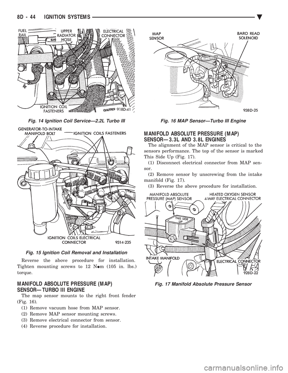
Reverse the above procedure for installation.
Tighten mounting screws to 12 N Im (105 in. lbs.)
torque.
MANIFOLD ABSOLUTE PRESSURE (MAP)
SENSORÐTURBO III ENGINE
The map sensor mounts to the right front fender
(Fig. 16). (1) Remove vacuum hose from MAP sensor.
(2) Remove MAP sensor mounting screws.
(3) Remove electrical connector from sensor.
(4) Reverse procedure for installation.
MANIFOLD ABSOLUTE PRESSURE (MAP)
SENSORÐ3.3L AND 3.8L ENGINES
The alignment of the MAP sensor is critical to the
sensors performance. The top of the sensor is marked
This Side Up (Fig. 17). (1) Disconnect electrical connector from MAP sen-
sor. (2) Remove sensor by unscrewing from the intake
manifold (Fig. 17). (3) Reverse the above procedure for installation.
Fig. 14 Ignition Coil ServiceÐ2.2L Turbo III
Fig. 15 Ignition Coil Removal and Installation
Fig. 16 MAP SensorÐTurbo III Engine
Fig. 17 Manifold Absolute Pressure Sensor
8D - 44 IGNITION SYSTEMS Ä
Page 491 of 2438
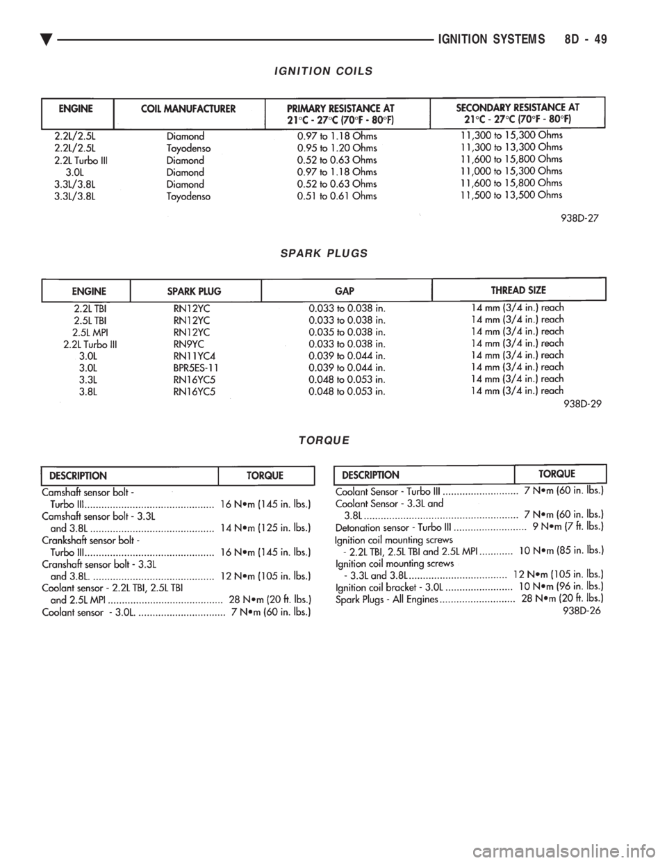
IGNITION COILS
SPARK PLUGS
TORQUE
Ä IGNITION SYSTEMS 8D - 49
Page 932 of 2438
Wiring Diagram
Name Sheet Number
Fan Control Relay ...........................33
Radiator Fan Motor ..........................33
Fog Lamps ............................. .55, 56
Fog Lamp Relay .............................48
Fog Lamp Switch .............................48
Front End Lighting ........................ .55, 56
Front Left Side Marker Lamp ....................56
Front Right Side Marker Lamp ...................55
Left Aero Hi-Low Beam Headlamp .................56
Left Fog Lamp .............................56
Left Park & Turn Signal Lamp ...................56
Right Aero Hi-Low Beam Headlamp ................55
Right Fog Lamp ............................55
Right Park & Turn Signal Lamp ..................55
Fuel Injection Ignition System (2.5L) .......12, 13, 14, 15, 16
Automatic Shutdown Relay ......................14
Distributor ................................15
Engine Coolant Sensor ........................15
EVAP/Purge Solenoid .........................13
Exhaust Gas Recirculation Diagnostic Solenoid .........13
Heated Oxygen Sensor ........................12
Idle Air Control Motor .........................12
Ignition Coil ...............................14
Injector ..................................16
MAP Sensor ...............................13
Powertrain Control Module ............12, 13, 14, 15, 16
Throttle Position (Sensor) ......................12
Vehicle Speed Senosr .........................15
Fuel Injection Ignition System Flex Fuel (2.5L Engine) ................ .17, 18, 19, 20, 21, 22
Auto Shutdown Relay ........................20
Distributor ...............................22
Engine Coolant Sensor ........................21
EVAP/Purge Solenoid .........................19
Fuel Sensor ...............................17
Heated Oxygen Sensor ........................18
Idle Air Control Motor ........................18
Ignition Coil ...............................20
Injectors .................................17
MAP Sensor ..............................19
Powertrain Control Module (PCM) . . . .17, 18, 19, 20, 21, 22
Throttle Position (Sensor) ......................18
Vehicle Speed Sensor ........................21
Fuel Injection Ignition System (3.0L) ............. .23, 24, 25, 26, 27, 28, 29, 30, 31
Automatic Shutdown Relay .....................28
Distributor ...............................27
Engine Coolant Sensor ........................27
Exhaust Gas Recirculation Diagnostic Solenoid .........24
EVAP/Purge Solenoid .........................23
Heated Oxygen Sensor ........................24
Idle Air Control Motor ........................30
Injectors .................................26
Ignition Coil ...............................29
MAP Sensor ..............................30
Power Steering Pressure Switch ..................25Wiring Diagram
Name Sheet Number
Powertrain Control Module (PCM) .............. .23, 24, 25, 27, 28, 29, 30, 31
Throttle Position (Sensor) ......................24
Vehicle Speed Sensor ........................28
Fuel Pump Motor .............................69
Fuel Pump Relay .............................70
Fuel Tank Electrical Systems ...................69, 70
Fuel Pump Motor ...........................69
Fuel Pump Relays ...........................70
Fuel Tank Level Gauge Sending Unit ...............69
Fuse Application Chart .....................1,2,3,4
Fuses Fuse 1 ..............................4,80,84
Fuse 2 .............4,5,39,40,53,74,80,84,87,89
Fuse 3 ..............................1,95,99
Fuse 4 ..............................1,95,99
Fuse 5 ...............1,49,51,68,71,72,84,87,89
Fuse 6 ..............................2,65,89
Fuse 7 ..............................3,11,59
Fuse 8 ......................3,11,44,45,47,77
Fuse 9 .........................3,11,68,71,72
Fuse 11 ...............3,9,11,16,22,37,47,60,84
Fuse 12 ...............................1,61
Fuse 14 ...............................2,48
Fuse 15 .......................2,45,47,48,106
Fuse 16 ..........................2,44,45,59
Fuse 18 .............................4,11,64
Fuse 19 .............................4,11,61
Fuse 20 ..........................4,11,87,89
Fuseblock Module & Relay Blank ..................107
Glove Box Lamp and Switch ......................54
Hazard Flasher ..............................61
Headlamp Dimmer Switch .....................1,50
Headlamp, Key-in, Seat Belt Chimes .................45
Headlamp Optical Horn Dimmer Switch .............1,50
Headlamp Switch ...........................1,49
Headlamp and Fog Lamp Switch ..............48, 49, 50
Fog Lamp Relay ............................48
Fog Lamp Switch ...........................48
Headlamp Switch ...........................49
Optical Horn & Headlamp Dimmer Switch ............50
Headlamp Switch Controlled Interior Lighting .........51, 52
A/C Lamps ...............................52
Ash Receiver Lamp ..........................52
Cigar Lighter Lamp ..........................52
Heater Lamp ..............................52
Radio Lamp ...............................52
Heated Oxygen Sensor ................... .12, 18, 24
Heated Rear Window ..........................84
Heated Rear Window .........................84
Switch ..................................84
Timer ...................................84
Heater System ...............................68
Bi-level Control Switch ........................68
Blower Motor ..............................68
Blower Slide Control .........................68
Heater Control Switch ........................68
8W - 182 WIRING DIAGRAMS AA-BODY Ä
Page 933 of 2438
Wiring Diagram
Name Sheet Number
Illumination Lamp ...........................68
Resistor .................................68
Horn System ...............................65
Horn (Hi-Note) .............................65
Horn (Lo-Note) ............................65
Horn Relay ...............................65
Horn Switch ..............................65
Hydraulic Modulator (ABS) 41
Ignition Coil .......................... .14, 20, 29
Ignition Off-Draw Connector .....................5,7
Ignition Switch .............................4,11
Brake Warning Lamp Switch ....................11
Park Brake Switch ...........................11
Illuminated Entry .............................58
Illuminated Entry Module ......................58
Left Door Illuminated Entry Switch ................58
Right Door Illuminated Entry Switch ...............58
Illuminated Visor Vanity Mirror ....................73
Injector(s) ........................... .16, 17, 26
Instrument Panel Wiring to Left Body ...............123
Instrument Panel Wiring to Right Body ..............124
Instrument Panel to Multi-Function Switch ............116
Interface Grommet ............................47
Intermittent Wiper System .................... .63, 64
Intermittent Windshield Wiper Motor ...............64
Intermittent Wiper Control Module ................64
Multi-function Switch .........................63
Windshield Washer Low Fluid Level Sensor ...........63
Windshield Washer Pump Motor .................63
Key-In Switch ...............................46
Key-In Warning Chimes .........................45
Lamp Outage Module ........................ .115
Lamps A/C Lamps ...............................52
Ash Receiver Lamp ..........................52
Back-Up Lamps ............ .93, 94, 98, 102, 103, 105
Cargo Lamp ........................ .76, 96, 100
Center High Mounted Stop Lamp ........94, 98, 102, 105
Cigar Lighter Lamp ..........................52
Cluster Lamp ..............................77
Courtesy Lamps ............................76
Dome Lamp ..............................73
Fog Lamp-Left .............................56
Fog Lamp-Right ............................55
Front Reading Lamp .........................75
Glove Box Lamp ............................54
Halo Lamp ...............................54
Headlamp-Left .............................56
Headlamp Out Lamp .........................77
Headlamp-Right ............................55
Heater Lamp ..............................52
Illumination Lamp ..................... .68, 71, 72
Left Front Door Ajar Lamp .....................77
Left Rear Door Ajar Lamp ......................77
Left Side Marker Lamp ........................93
Left Tail/Stop and Turn Lamp ....................93
License Lamp ................... .93, 98, 102, 104Wiring Diagram
Name Sheet Number
Liftgate Ajar Lamp ..........................77
Low Washer Fluid Lamp .......................77
Park/Turn Lamp-Left .........................56
Park/Turn Lamp-Right ........................55
Radio Lamp ...............................52
Reading Lamps ............................75
Right Front Door Ajar Lamp ....................77
Right Rear Door Ajar Lamp .....................77
Seat Belt Warning Lamp .......................45
Side Marker Lamp-Left Front ....................56
Side Marker Lamp-Left Rear ...........93, 98, 102, 103
Side Marker Lamp-Right Front ...................55
Side Marker Lamp-Right Rear ..........94, 98, 102, 105
Stop Lamp Out Lamp ........................77
Tail Lamp Out Lamp .........................77
Tail/Stop Lamp-Left Rear ................... .93, 98
Tail/Stop Lamp-Right Rear .................. .94, 98
Tail/Stop and Turn Lamp-Left Rear .......93, 98, 102, 103
Tail/Stop and Turn Lamp-Right Rear ......94, 98, 102, 105
Transmission Range Indicator Lamp ...............76
Underhood Lamp ........................ .39, 40
Visor Vanity Mirror Lamp ......................73
Left Power Seat System ........................66
Center Switch .............................66
Front Switch ..............................66
Power Seat Motors ..........................66
Rear Switch ...............................66
License Lamp ..................... .93, 98, 102, 104
Lighter-Cigar ................................52
MAP Sensor .......................... .13, 19, 30
Message Center ..............................60
Traveler and Message Center ....................60
Mini Trip Computer ...........................60
Modules Airbag System Diagnostic Module .................47
Daytime Running Light Module ..................57
Illuminated Entry Module ......................58
Intermittent Wiper Control Module ................64
Lamp Outage Module ..................... .95, 99
Motors A/C-Heater Blower Motor ................... .71, 72
Fuel Pump Motor ...........................69
Heater Blower Motor .........................68
Idle Air Control Motor .................. .12, 18, 30
Intermittent Wiper Motor ......................64
Power Door Locks Motors .................. .85, 86
Power Seat Motors ..........................66
Power Window Motors .................... .81, 82
Radiator Fan Motor ...................... .32, 33
Starter Motor ............................9,10
Windshield Washer Pump Motor .................63
Name Brand Speaker Relay ......................89
Optical Horn Headlamp Dimmer Switch .............1,50
Overhead Console, Dome, Reading and Visor Vanity Lamps ..................... .73, 74, 75, 76
Ambient Temperature Sensor ....................75
Cargo Lamp ..............................76
Ä WIRING DIAGRAMS AA-BODY 8W - 183
Page 936 of 2438
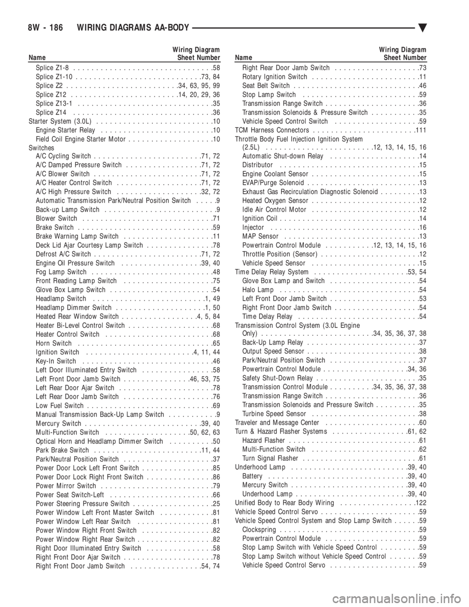
Wiring Diagram
Name Sheet Number
Splice Z1-8 ...............................58
Splice Z1-10 ........................... .73, 84
Splice Z2 ........................ .34, 63, 95, 99
Splice Z12 ....................... .14, 20, 29, 36
Splice Z13-1 ..............................35
Splice Z14 ...............................36
Starter System (3.0L) ..........................10
Engine Starter Relay .........................10
Field Coil Engine Starter Motor ...................10
Switches A/C Cycling Switch ....................... .71, 72
A/C Damped Pressure Switch .................71, 72
A/C Blower Switch ....................... .71, 72
A/C Heater Control Switch .................. .71, 72
A/C High Pressure Switch .................. .32, 72
Automatic Transmission Park/Neutral Position Switch .....9
Back-up Lamp Switch .........................9
Blower Switch .............................71
Brake Switch ..............................59
Brake Warning Lamp Switch ....................11
Deck Lid Ajar Courtesy Lamp Switch ...............78
Defrost A/C Switch ....................... .71, 72
Engine Oil Pressure Switch ..................39, 40
Fog Lamp Switch ...........................48
Front Reading Lamp Switch ....................75
Glove Box Lamp Switch .......................54
Headlamp Switch .........................1,49
Headlamp Dimmer Switch ....................1,50
Heated Rear Window Switch .................4,5,84
Heater Bi-Level Control Switch ...................68
Heater Control Switch ........................68
Horn Switch ..............................65
Ignition Switch ........................4,11,44
Key-In Switch .............................46
Left Door Illuminated Entry Switch ................58
Left Front Door Jamb Switch ...............46, 53, 75
Left Rear Door Ajar Switch .....................78
Left Rear Door Jamb Switch ....................76
Low Fuel Switch ............................69
Manual Transmission Back-Up Lamp Switch ...........9
Mercury Switch ......................... .39, 40
Multi-Function Switch .................. .50, 62, 63
Optical Horn and Headlamp Dimmer Switch ..........50
Park Brake Switch ....................... .11, 44
Park/Neutral Position Switch ....................37
Power Door Lock Left Front Switch ................85
Power Door Lock Right Front Switch ...............86
Power Mirror Switch .........................79
Power Seat Switch-Left .......................66
Power Steering Pressure Switch ..................25
Power Window Left Front Master Switch ............81
Power Window Left Rear Switch .................81
Power Window Right Front Switch ................82
Power Window Right Rear Switch .................82
Right Door Illuminated Entry Switch ...............58
Right Front Door Ajar Switch ....................78
Right Front Door Jamb Switch ................54, 74Wiring Diagram
Name Sheet Number
Right Rear Door Jamb Switch ...................73
Rotary Ignition Switch ........................11
Seat Belt Switch ............................46
Stop Lamp Switch ..........................59
Transmission Range Switch .....................36
Transmission Solenoids & Pressure Switch ...........35
Vehicle Speed Control Switch ...................59
TCM Harness Connectors ...................... .111
Throttle Body Fuel Injection Ignition System (2.5L) ....................... .12, 13, 14, 15, 16
Automatic Shut-down Relay ....................14
Distributor ...............................15
Engine Coolant Sensor ........................15
EVAP/Purge Solenoid .........................13
Exhaust Gas Recirculation Diagnostic Solenoid .........13
Heated Oxygen Sensor ........................12
Idle Air Control Motor ........................12
Ignition Coil ...............................14
Injector .................................16
MAP Sensor ..............................13
Powertrain Control Module ...........12, 13, 14, 15, 16
Throttle Position (Sensor) ......................12
Vehicle Speed Sensor ........................15
Time Delay Relay System .................... .53, 54
Glove Box Lamp and Switch ....................54
Halo Lamp ...............................54
Left Front Door Jamb Switch ....................53
Right Front Door Jamb Switch ...................54
Time Delay Relay ...........................54
Transmission Control System (3.0L Engine Only) ........................ .34, 35, 36, 37, 38
Back-Up Lamp Relay .........................37
Output Speed Sensor .........................38
Park/Neutral Position Switch ....................37
Powertrain Control Module .................. .34, 36
Safety Shut-Down Relay .......................35
Transmission Control Module ..........34, 35, 36, 37, 38
Transmission Range Switch .....................36
Transmission Solenoids and Pressure Switch ..........35
Turbine Speed Sensor ........................38
Traveler and Message Center .....................60
Turn & Hazard Flasher Systems .................61, 62
Hazard Flasher .............................61
Multi-Function Switch ........................62
Turn Signal Flasher ..........................61
Underhood Lamp ......................... .39, 40
Battery .............................. .39, 40
Mercury Switch ......................... .39, 40
Underhood Lamp ........................ .39, 40
Unified Body to Rear Body Wiring .................122
Vehicle Speed Control Servo ......................59
Vehicle Speed Control System and Stop Lamp Switch ......59
Clockspring ...............................59
Powertrain Control Module .....................59
Stop Lamp Switch with Vehicle Speed Control .........59
Stop Lamp Switch without Vehicle Speed Control .......59
Vehicle Speed Control Servo ....................59
8W - 186 WIRING DIAGRAMS AA-BODY Ä
Page 1066 of 2438
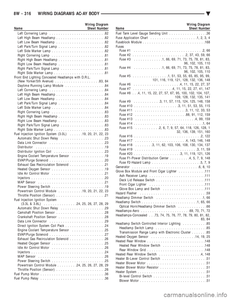
Wiring Diagram
Name Sheet Number
Left Cornering Lamp .........................82
Left High Beam Headlamp ......................82
Left Low Beam Headlamp ......................82
Left Park/Turn Signal Lamp .....................82
Left Side Marker Lamp ........................82
Right Cornering Lamp ........................81
Right High Beam Headlamp .....................81
Right Low Beam Headlamp .....................81
Right Park/Turn Signal Lamp ....................81
Right Side Marker Lamp .......................81
Front End Lighting Concealed Headlamps with D.R.L. (New Yorker/5th Avenue) ................... .83, 84
Daytime Running Lamp Module ..................84
Left Cornering Lamp .........................84
Left High Beam Headlamp ......................84
Left Low Beam Headlamp ......................84
Left Park/Turn Signal Lamp .....................84
Left Side Marker Lamp ........................84
Right Cornering Lamp ........................83
Right High Beam Headlamp .....................83
Right Low Beam Headlamp .....................83
Right Park/Turn Signal Lamp ....................83
Right Side Marker Lamp .......................83
Fuel Injection Ignition System (3.0L) ......19, 20, 21, 22, 23
Automatic Shut Down Relay ....................23
Data Link Connector .........................23
Distributor ...............................19
Distributor Ignition Coil .......................23
Engine Coolant Temperature Sensor ...............19
EVAP/Purge Solenoid .........................20
Exhaust Gas Recirculation Solenoid ................21
Heated Oxygen Sensor ........................19
Idle Air Control Motor ........................21
Injectors .................................20
MAP Sensor ..............................21
Power Steering Switch ........................19
Powertrain Control Module ...........19, 20, 21, 22, 23
Throttle Position (Sensor) ......................21
Fuel Injection Ignition System (3.3L & 3.8L) .............. .24, 25, 26, 27, 28, 29
Automatic Shut Down Relay ....................29
Camshaft Position Sensor ......................28
Crankshaft Position Sensor .....................28
Data Link Connector .........................29
Direct Ignition System Coil Pack ..................24
Engine Coolant Temperature Sensor ...............25
EVAP/Purge Solenoid .........................27
Exhaust Gas Recirculation Solenoid ................26
Heated Oxygen Sensor ........................25
Idle Air Control Motor ........................26
Injectors .................................24
MAP Sensor ..............................26
Power Steering Switch ........................25
Powertrain Control Module .........24, 25, 26, 27, 28, 29
Throttle Position (Sensor) ......................26
Fuel Pump Motor .............................36
Fuel Pump Relay .............................36Wiring Diagram
Name Sheet Number
Fuel Tank Level Gauge Sending Unit .................36
Fuse Application Chart .....................1,2,3,4
Fuseblock Module ........................... .168
Fuses Fuse #1 ...............................2,66
Fuse #2 ........................2,37,43,59,66
Fuse #3 .............1,66,69,71,73,75,78,81,83,
96, 102, 105, 110
Fuse #4 .............1,66,69,71,73,75,78,81,83,
96, 102, 105, 110
Fuse #5 ................1,51,53,55,65,85,95,99,
101, 116, 119, 121, 128, 132, 136, 148
Fuse #6 .....................4,11,15,22,27,37
Fuse #7 ..................4,11,15,22,27,41,147
Fuse #8 . . .4, 11, 15, 22, 27, 57, 67, 95, 100, 102, 104, 107, 109, 128, 132, 135, 141
Fuse #9 ............3,11,57, 115, 124, 125, 148, 158
Fuse #10 ....................3,11,51,53,55,115
Fuse #11 .......................3,11,12,33,53
Fuse #12 ...................... .88, 91, 112, 159
Fuse #13 ...........................4,99,159
Fuse #14 ...............................1,64
Fuse #15 ...........2,6,7,9,57,64, 118, 126, 128, 1
32, 136, 139, 151, 160
Fuse #16 ..............................2,122
Fuse #17 .......................4, 143, 146, 148
Fuse #18 ........3,11,62, 103, 106, 108, 130, 134, 137
Fuse #19 ............................3,11,59
Fuse #20 .....................3,11, 119, 121, 126
Fuse F1-Power Distribution Center .........4,5,7,9,148
Fuse F2-Hazard Lamp ......................5,7,9
Generator ..............................6,8,10
Glove Box Module and Front Cigar Lighter ............111
Ash Receiver Lamp ........................ .111
Deck Lid Release Switch ..................... .111
Front Cigar Lighter ........................ .111
Glove Box Lamp and Switch ...................111
Hazard Flasher ..............................59
Headlamp Dimmer Switch .....................1,66
Headlamp Switch .........................1,65,66
Optical Horn/Headlamp Dimmer Switch .............66
Headlamps-Aero ..................... .69, 70, 71, 72
Headlamps-Concealed . . .73, 74, 75, 76, 77, 78, 79, 80, 81, 82, 83, 84
Headlamp Switch Controlled Interior Lighting ...........85
Headlamp Switch Lamp .......................85
Transmission Range Lamp with Electronic Cluster .......85
Heated Oxygen Sensor ................... .14, 19, 25
Heated Rear Window ......................... .148
Heated Rear Window Switch ...................148
Rear Window Grid ......................... .148
Heated Rear Window Switch ...................4,148
Heater Bi-Lever Control Switch ....................51
Heater Blower Motor ...........................51
Heater Blower Motor Resistor .....................51
Heater System ...............................51
Bi-level Control Switch ........................51
Blower Motor ..............................51
8W - 316 WIRING DIAGRAMS AC-AY BODY Ä