1993 CHEVROLET PLYMOUTH ACCLAIM Ignition coil
[x] Cancel search: Ignition coilPage 1906 of 2438

S/C Vacuum Solenoid
A/C Clutch Relay
EGR Solenoid
Auto Shutdown Relay
Radiator Fan Relay
Purge Solenoid
Malfunction Indicator Lamp (Check Engine Lamp)
STATE DISPLAY SENSORS
Connect the DRBII scan tool to the vehicle and ac-
cess the State Display screen. Then access Sensor
Display. The following is a list of the engine control
system functions accessible through the Sensor Dis-
play screen. Oxygen Sensor Signal
Engine Coolant Temperature
Engine Coolant Temp Sensor
Throttle Position
Minimum Throttle
Battery Voltage
MAP Sensor Reading
Idle Air Control Motor Position
Adaptive Fuel Factor
Barometric Pressure
Min Airflow Idle Spd (speed)
Engine Speed
DIS Sensor Status
Fault #1 Key-On Info
Module Spark Advance
Speed Control Target
Fault #2 Key-on Info
Fault #3 Key-on Info
Speed Control Status
Speed Control Switch Voltage
Charging System Goal
Theft Alarm Status
Map Sensor Voltage
Vehicle Speed
Oxygen Sensor State
MAP Gauge Reading
Throttle Opening (percentage)
Total Spark Advance
CIRCUIT ACTUATION TEST MODE
The circuit actuation test mode checks for proper
operation of output circuits or devices which the pow-
ertrain control module (PCM) cannot internally rec-
ognize. The PCM can attempt to activate these
outputs and allow an observer to verify proper oper-
ation. Most of the tests provide an audible or visual
indication of device operation (click of relay contacts,
spray fuel, etc.). Except for intermittent conditions, if
a device functions properly during testing, assume
the device, its associated wiring, and driver circuit
working correctly.
OBTAINING CIRCUIT ACTUATION TEST
Connect the DRBII scan tool to the vehicle and ac-
cess the Actuators screen. The following is a list of
the engine control system functions accessible
through Actuators screens. Stop All Tests
Ignition Coil #1
Ignition Coil #2
Ignition Coil #3
Fuel Injector #1
Fuel Injector #2
Fuel Injector #3
Fuel Injector #4
Fuel Injector #5
Fuel Injector #6
Idle Air Control Motor Open/Close
Radiator Fan Relay
A/C Clutch Relay
Auto Shutdown Relay
EVAP Purge Solenoid
S/C Servo Solenoids
Generator Field
EGR Solenoid
All Solenoids/Relays
ASD Fuel System Test
Speed Control Vacuum Solenoid
Speed Control Vent Solenoid
THROTTLE BODY MINIMUM AIR FLOW CHECK
PROCEDURE
(1) Warm engine in Park or Neutral until the cool-
ing fan has cycled on and off at least once. (2) Ensure that all accessories are off.
(3) Shut off engine.
(4) Disconnect the PCV valve hose from the intake
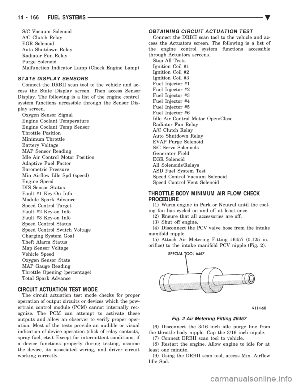
manifold nipple. (5) Attach Air Metering Fitting #6457 (0.125 in.
orifice) to the intake manifold PCV nipple (Fig. 2).
(6) Disconnect the 3/16 inch idle purge line from
the throttle body nipple. Cap the 3/16 inch nipple. (7) Connect DRBII scan tool to vehicle.
(8) Restart the engine. Allow engine to idle for at
least one minute. (9) Using the DRBII scan tool, access Min. Airflow
Idle Spd.
Fig. 2 Air Metering Fitting #6457
14 - 166 FUEL SYSTEMS Ä
Page 1912 of 2438

(12) Remove the fuel hose quick connect fittings
from the chassis tubes. Refer to Fuel Hoses, Clamps
and Quick Connect Fittings in the Fuel Delivery
Section of this Group. Place a shop towel under the
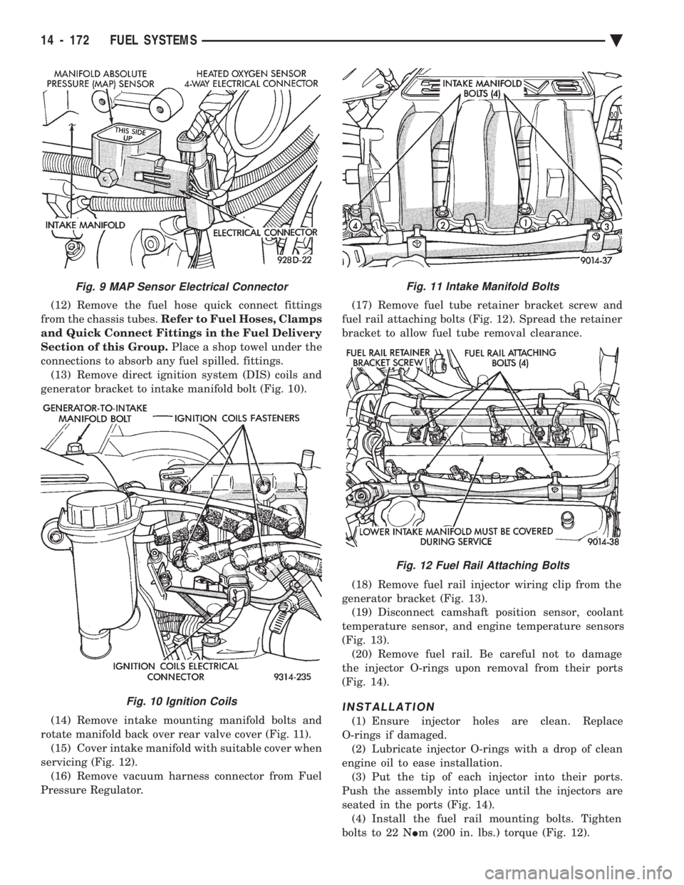
connections to absorb any fuel spilled. fittings. (13) Remove direct ignition system (DIS) coils and
generator bracket to intake manifold bolt (Fig. 10).
(14) Remove intake mounting manifold bolts and
rotate manifold back over rear valve cover (Fig. 11). (15) Cover intake manifold with suitable cover when
servicing (Fig. 12). (16) Remove vacuum harness connector from Fuel
Pressure Regulator. (17) Remove fuel tube retainer bracket screw and
fuel rail attaching bolts (Fig. 12). Spread the retainer
bracket to allow fuel tube removal clearance.
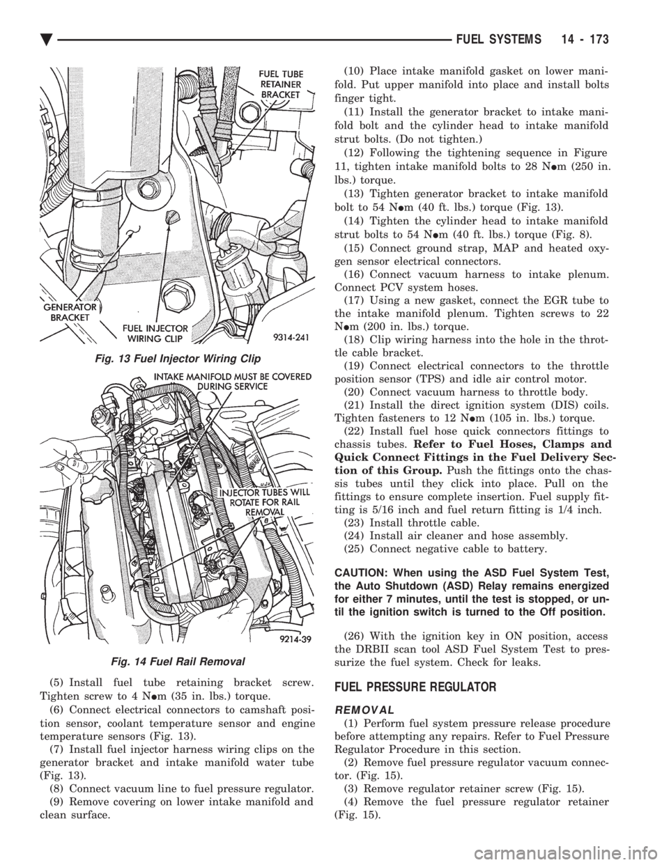
(18) Remove fuel rail injector wiring clip from the
generator bracket (Fig. 13). (19) Disconnect camshaft position sensor, coolant
temperature sensor, and engine temperature sensors
(Fig. 13). (20) Remove fuel rail. Be careful not to damage
the injector O-rings upon removal from their ports
(Fig. 14).
INSTALLATION
(1) Ensure injector holes are clean. Replace
O-rings if damaged. (2) Lubricate injector O-rings with a drop of clean
engine oil to ease installation. (3) Put the tip of each injector into their ports.
Push the assembly into place until the injectors are
seated in the ports (Fig. 14). (4) Install the fuel rail mounting bolts. Tighten
bolts to 22 N Im (200 in. lbs.) torque (Fig. 12).
Fig. 11 Intake Manifold Bolts
Fig. 12 Fuel Rail Attaching Bolts
Fig. 9 MAP Sensor Electrical Connector
Fig. 10 Ignition Coils
14 - 172 FUEL SYSTEMS Ä
Page 1913 of 2438

(5) Install fuel tube retaining bracket screw.
Tighten screw to 4 N Im (35 in. lbs.) torque.
(6) Connect electrical connectors to camshaft posi-
tion sensor, coolant temperature sensor and engine
temperature sensors (Fig. 13). (7) Install fuel injector harness wiring clips on the
generator bracket and intake manifold water tube
(Fig. 13). (8) Connect vacuum line to fuel pressure regulator.
(9) Remove covering on lower intake manifold and
clean surface. (10) Place intake manifold gasket on lower mani-
fold. Put upper manifold into place and install bolts
finger tight. (11) Install the generator bracket to intake mani-
fold bolt and the cylinder head to intake manifold
strut bolts. (Do not tighten.) (12) Following the tightening sequence in Figure
11, tighten intake manifold bolts to 28 N Im (250 in.
lbs.) torque. (13) Tighten generator bracket to intake manifold
bolt to 54 N Im (40 ft. lbs.) torque (Fig. 13).
(14) Tighten the cylinder head to intake manifold
strut bolts to 54 N Im (40 ft. lbs.) torque (Fig. 8).
(15) Connect ground strap, MAP and heated oxy-
gen sensor electrical connectors. (16) Connect vacuum harness to intake plenum.
Connect PCV system hoses. (17) Using a new gasket, connect the EGR tube to
the intake manifold plenum. Tighten screws to 22
N Im (200 in. lbs.) torque.
(18) Clip wiring harness into the hole in the throt-
tle cable bracket. (19) Connect electrical connectors to the throttle
position sensor (TPS) and idle air control motor. (20) Connect vacuum harness to throttle body.
(21) Install the direct ignition system (DIS) coils.
Tighten fasteners to 12 N Im (105 in. lbs.) torque.
(22) Install fuel hose quick connectors fittings to
chassis tubes. Refer to Fuel Hoses, Clamps and
Quick Connect Fittings in the Fuel Delivery Sec-
tion of this Group. Push the fittings onto the chas-
sis tubes until they click into place. Pull on the
fittings to ensure complete insertion. Fuel supply fit-
ting is 5/16 inch and fuel return fitting is 1/4 inch. (23) Install throttle cable.
(24) Install air cleaner and hose assembly.
(25) Connect negative cable to battery.
CAUTION: When using the ASD Fuel System Test,
the Auto Shutdown (ASD) Relay remains energized
for either 7 minutes, until the test is stopped, or un-
til the ignition switch is turned to the Off position.
(26) With the ignition key in ON position, access
the DRBII scan tool ASD Fuel System Test to pres-
surize the fuel system. Check for leaks.FUEL PRESSURE REGULATOR
REMOVAL
(1) Perform fuel system pressure release procedure
before attempting any repairs. Refer to Fuel Pressure
Regulator Procedure in this section. (2) Remove fuel pressure regulator vacuum connec-
tor. (Fig. 15). (3) Remove regulator retainer screw (Fig. 15).
(4) Remove the fuel pressure regulator retainer
(Fig. 15).
Fig. 13 Fuel Injector Wiring Clip
Fig. 14 Fuel Rail Removal
Ä FUEL SYSTEMS 14 - 173
Page 2352 of 2438

WARNING: AVOID RADIATOR/CONDENSER FAN
BLADES WHEN WORKING IN THE RADIATOR
AREA. FAN IS CONTROLLED BY TEMPERATURE
AND CAN START ANY TIME IGNITION IS ON. PER-
SONAL INJURY CAN RESULT.
(1) Disconnect fan control switch wire connector.
(2) Using a suitable jumper wire, jump across ter-
minals in wire connector. (3) Connect a suitable continuity tester across fan
control switch terminals. (4) Start engine and set idle at 1300 rpm. The ra-
diator fan should run constantly. (5) Set the A/C controls to A/C and high blower.
(6) If the high pressure gauge reads below 1102
kPa (160 psi) there should be no continuity across
the switch terminals.
CAUTION: Do not allow engine to overheat when ra-
diator air flow is blocked.
(7) Block radiator air flow with a suitable cover to
increase the high side pressure to at least 1585 kPa
(230 psi). Electrical continuity should be detected
across the fan control switch terminals. (8) Remove cover from front of vehicle to allow
high side pressure to decrease. When pressure drops
below 1102 kPa (160 psi), continuity should cease. If fan control switch is defective, replace it.
REMOVAL AND INSTALLATION
CAUTION: Refrigerant removal is not necessary
when removing the Condenser Fan Control Switch.
However, a small amount of refrigerant will vent
from the switch port. Review the refrigerant han-
dling section of Safety Precautions and Warnings in
the General Information section of this Group.
(1) Disconnect wire connector from condenser fan
control switch. (2) Loosen and quickly rotate the switch counter-
clockwise and separate from the high pressure line
switch port. To install, reverse the preceding operation.
DIFFERENTIAL PRESSURE CUT-OUT SWITCH
DIAGNOSIS
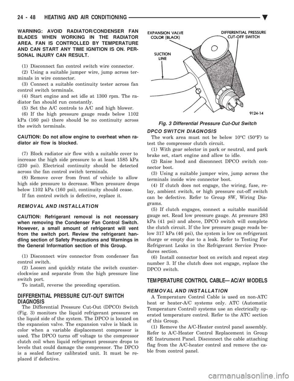
The Differential Pressure Cut-Out (DPCO) Switch
(Fig. 3) monitors the liquid refrigerant pressure on
the liquid side of the system. The DPCO is located on
the expansion valve. The expansion valve is black in
color when a variable displacement compressor is
used. The DPCO turns off voltage to the compressor
clutch coil when liquid refrigerant pressure drops to
levels that could damage the compressor. The DPCO
is a sealed factory calibrated unit. It must be re-
placed if defective.
DPCO SWITCH DIAGNOSIS
The work area must not be below 10ÉC (50ÉF) to
test the compressor clutch circuit. (1) With gear selector in park or neutral, and park
brake set, start engine and allow to idle. (2) Raise hood and disconnect DPCO switch con-
nector boot. (3) Using a suitable jumper wire, jump across the
terminals inside wire connector boot. (4) If clutch does not engage, the wiring, fuse, re-
lay, ambient switch, or high pressure cut-off switch
can be defective. Refer to Group 8W, Wiring Dia-
grams. (5) If clutch engages, connect a suitable manifold
gauge set. Read low pressure gauge. At pressure 283
kPa (41 psi) and above, DPCO switch will complete
the clutch circuit. If the low pressure gauge reads be-
low 317 kPa (46 psi), the system is low on refrigerant
charge or empty due to a leak. Refer to Testing For
Refrigerant Leaks in the Refrigerant Service Proce-
dures section. (6) Install connector boot on switch and repeat step
number 3. If the clutch does not engage, replace the
DPCO switch.
TEMPERATURE CONTROL CABLEÐAC/AY MODELS
REMOVAL AND INSTALLATION
A Temperature Control Cable is used on non-ATC
heat or heater-A/C systems only. ATC (Automatic
Temperature Control) systems use an electrically op-
erated temperature control. Refer to the ATC section
of this Group. (1) Remove the A/C-Heater control panel assembly.
Refer to A/C-Heater Control Replacement in Group
8E Instrument Panel. Disconnect the cable attaching
flag from the A/C-heater control and remove the ca-
ble from control panel.
Fig. 3 Differential Pressure Cut-Out Switch
24 - 48 HEATING AND AIR CONDITIONING Ä