1993 CHEVROLET PLYMOUTH ACCLAIM oil filter
[x] Cancel search: oil filterPage 1660 of 2438
OIL FILTER AND BRACKET
BRACKET INSPECTION
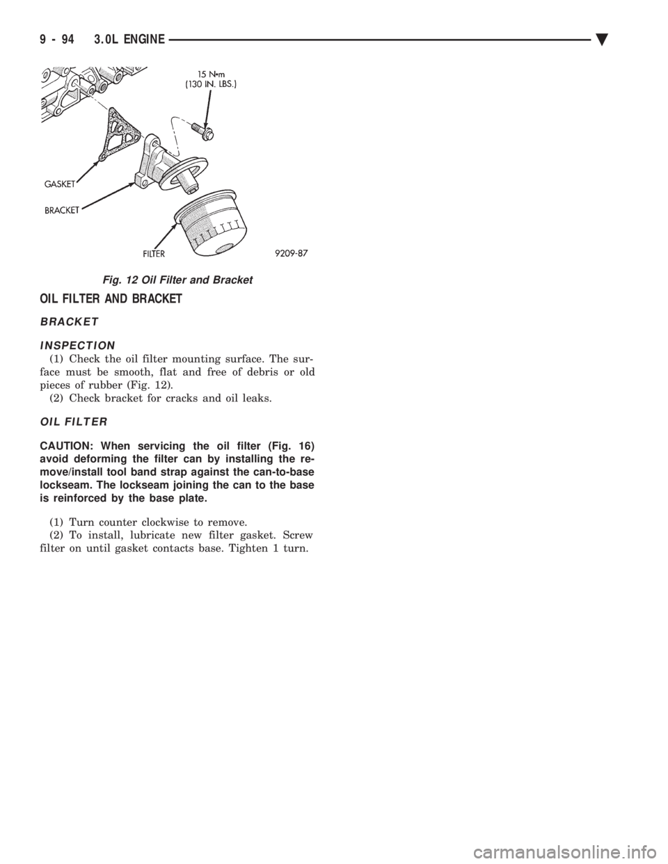
(1) Check the oil filter mounting surface. The sur-
face must be smooth, flat and free of debris or old
pieces of rubber (Fig. 12). (2) Check bracket for cracks and oil leaks.
OIL FILTER
CAUTION: When servicing the oil filter (Fig. 16)
avoid deforming the filter can by installing the re-
move/install tool band strap against the can-to-base
lockseam. The lockseam joining the can to the base
is reinforced by the base plate.
(1) Turn counter clockwise to remove.
(2) To install, lubricate new filter gasket. Screw
filter on until gasket contacts base. Tighten 1 turn.
Fig. 12 Oil Filter and Bracket
9 - 94 3.0L ENGINE Ä
Page 1664 of 2438
3.3/3.8L ENGINE INDEX
page page
Camshaft .............................. 112
Camshaft BearingsÐEngine Removed From Vehicle .............................. 113
Checking Engine Oil Pressure .............. 125
Connecting Rods ........................ 118
Crankshaft Oil Seals Service ............... 121
Crankshaft Service ...................... 118
Cylinder Block, Piston and Connecting Rod Assembly Service ...................... 114
Cylinder Heads ......................... 102
Engine Assembly ........................ 101
Engine Core Oil and Cam Plugs ............ 113
Engine Lubrication System ................ 122 Engine Mounts
.......................... 99
Engine Specifications ..................... 126
General Information ....................... 98
Hydraulic Tappets ....................... 108
Installing Piston and Connecting Rod Assembly . 117
Intake Manifold Sealing ................... 104
Oil Filter .............................. 125
Oil Pan Service ......................... 122
Oil Pump Service ....................... 123
Rocker Arms and Shaft Assembly ........... 102
Timing Chain Cover, Oil Seal and Chain ...... 109
Valve Service .......................... 104
Valve Timing ........................... 109
GENERAL INFORMATION
ENGINE IDENTIFICATION NUMBER OR CODE
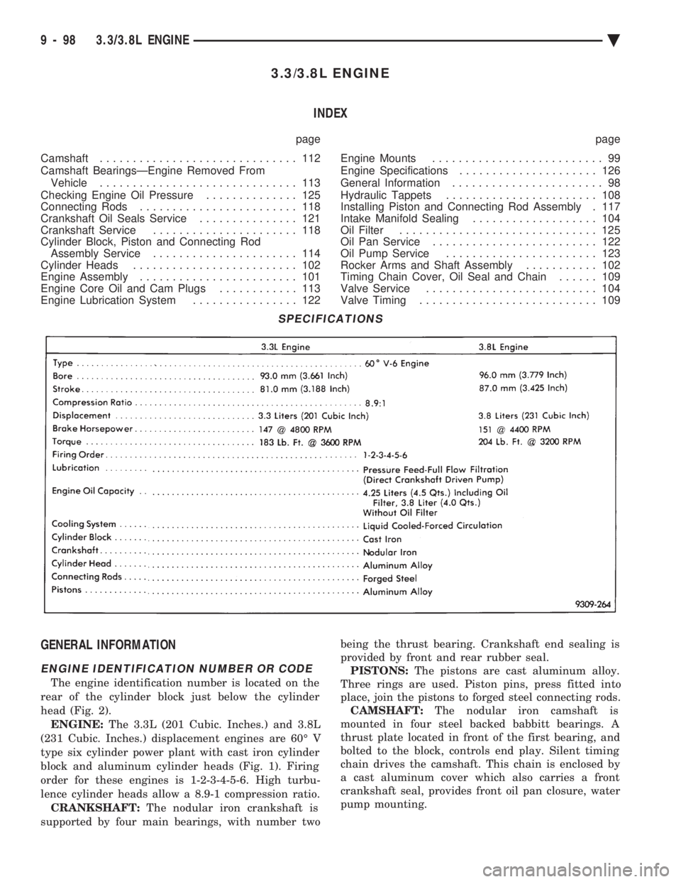
The engine identification number is located on the
rear of the cylinder block just below the cylinder
head (Fig. 2). ENGINE: The 3.3L (201 Cubic. Inches.) and 3.8L
(231 Cubic. Inches.) displacement engines are 60É V
type six cylinder power plant with cast iron cylinder
block and aluminum cylinder heads (Fig. 1). Firing
order for these engines is 1-2-3-4-5-6. High turbu-
lence cylinder heads allow a 8.9-1 compression ratio. CRANKSHAFT: The nodular iron crankshaft is
supported by four main bearings, with number two being the thrust bearing. Crankshaft end sealing is
provided by front and rear rubber seal. PISTONS: The pistons are cast aluminum alloy.
Three rings are used. Piston pins, press fitted into
place, join the pistons to forged steel connecting rods. CAMSHAFT: The nodular iron camshaft is
mounted in four steel backed babbitt bearings. A
thrust plate located in front of the first bearing, and
bolted to the block, controls end play. Silent timing
chain drives the camshaft. This chain is enclosed by
a cast aluminum cover which also carries a front
crankshaft seal, provides front oil pan closure, water
pump mounting.
SPECIFICATIONS
9 - 98 3.3/3.8L ENGINE Ä
Page 1688 of 2438
ENGINE LUBRICATION SYSTEM
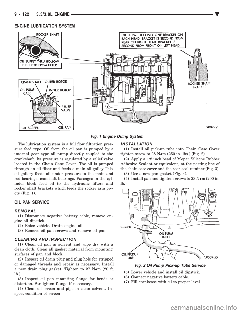
The lubrication system is a full flow filtration pres-
sure feed type. Oil from the oil pan is pumped by a
internal gear type oil pump directly coupled to the
crankshaft. Its pressure is regulated by a relief valve
located in the Chain Case Cover. The oil is pumped
through an oil filter and feeds a main oil galley.This
oil gallery feeds oil under pressure to the main and
rod bearings, camshaft bearings. Passages in the cyl-
inder block feed oil to the hydraulic lifters and
rocker shaft brackets which feeds the rocker arm piv-
ots (Fig. 1).
OIL PAN SERVICE
REMOVAL
(1) Disconnect negative battery cable, remove en-
gine oil dipstick. (2) Raise vehicle. Drain engine oil.
(3) Remove oil pan screws and remove oil pan.
CLEANING AND INSPECTION
(1) Clean oil pan in solvent and wipe dry with a
clean cloth. Clean all gasket material from mounting
surfaces of pan and block. (2) Inspect oil drain plug and plug hole for stripped
or damaged threads and repair as necessary. Install
a new drain plug gasket. Tighten to 27 N Im (20 ft.
lb.). (3) Inspect oil pan mounting flange for bends or
distortion. Straighten flange if necessary. (4) Clean oil screen and pipe in clean solvent. In-
spect condition of screen.
INSTALLATION
(1) Install oil pick-up tube into Chain Case Cover
tighten screw to 28 N Im (250 in. lbs.) (Fig. 2).
(2) Apply a 1/8 inch bead of Mopar Silicone Rubber
Adhesive Sealant or equivalent, at the parting line of
the chain case cover and the rear seal retainer (Fig. 3). (3) Use a new pan gasket (Fig. 4).
(4) Install pan and tighten screws to 23 N Im (200 in.
lb.).
(5) Lower vehicle and install oil dipstick.
(6) Connect negative battery cable.
(7) Fill crankcase with oil to proper level.
Fig. 1 Engine Oiling System
Fig. 2 Oil Pump Pick-up Tube Service
9 - 122 3.3/3.8L ENGINE Ä
Page 1691 of 2438
CHECKING ENGINE OIL PRESSURE
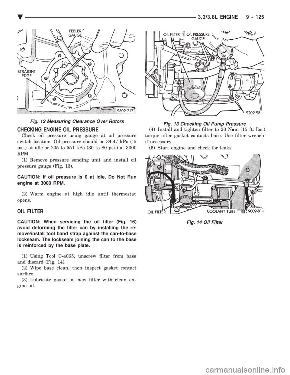
Check oil pressure using gauge at oil pressure
switch location. Oil pressure should be 34.47 kPa ( 5
psi.) at idle or 205 to 551 kPa (30 to 80 psi.) at 3000
RPM. (1) Remove pressure sending unit and install oil
pressure gauge (Fig. 13).
CAUTION: If oil pressure is 0 at idle, Do Not Run
engine at 3000 RPM .
(2) Warm engine at high idle until thermostat
opens.
OIL FILTER
CAUTION: When servicing the oil filter (Fig. 16)
avoid deforming the filter can by installing the re-
move/install tool band strap against the can-to-base
lockseam. The lockseam joining the can to the base
is reinforced by the base plate.
(1) Using Tool C-4065, unscrew filter from base
and discard (Fig. 14). (2) Wipe base clean, then inspect gasket contact
surface. (3) Lubricate gasket of new filter with clean en-
gine oil. (4) Install and tighten filter to 20 N
Im (15 ft. lbs.)
torque after gasket contacts base. Use filter wrench
if necessary. (5) Start engine and check for leaks.
Fig. 12 Measuring Clearance Over RotorsFig. 13 Checking Oil Pump Pressure
Fig. 14 Oil Filter
Ä 3.3/3.8L ENGINE 9 - 125
Page 1705 of 2438
EXHAUST MANIFOLD
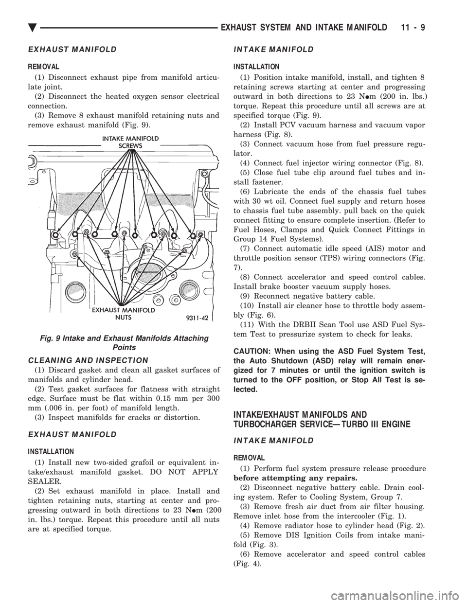
REMOVAL (1) Disconnect exhaust pipe from manifold articu-
late joint. (2) Disconnect the heated oxygen sensor electrical
connection. (3) Remove 8 exhaust manifold retaining nuts and
remove exhaust manifold (Fig. 9).
CLEANING AND INSPECTION
(1) Discard gasket and clean all gasket surfaces of
manifolds and cylinder head. (2) Test gasket surfaces for flatness with straight
edge. Surface must be flat within 0.15 mm per 300
mm (.006 in. per foot) of manifold length. (3) Inspect manifolds for cracks or distortion.
EXHAUST MANIFOLD
INSTALLATION
(1) Install new two-sided grafoil or equivalent in-
take/exhaust manifold gasket. DO NOT APPLY
SEALER. (2) Set exhaust manifold in place. Install and
tighten retaining nuts, starting at center and pro-
gressing outward in both directions to 23 N Im (200
in. lbs.) torque. Repeat this procedure until all nuts
are at specified torque.
INTAKE MANIFOLD
INSTALLATION
(1) Position intake manifold, install, and tighten 8
retaining screws starting at center and progressing
outward in both directions to 23 N Im (200 in. lbs.)
torque. Repeat this procedure until all screws are at
specified torque (Fig. 9). (2) Install PCV vacuum harness and vacuum vapor
harness (Fig. 8). (3) Connect vacuum hose from fuel pressure regu-
lator. (4) Connect fuel injector wiring connector (Fig. 8).
(5) Close fuel tube clip around fuel tubes and in-
stall fastener. (6) Lubricate the ends of the chassis fuel tubes
with 30 wt oil. Connect fuel supply and return hoses
to chassis fuel tube assembly. pull back on the quick
connect fitting to ensure complete insertion. (Refer to
Fuel Hoses, Clamps and Quick Connect Fittings in
Group 14 Fuel Systems). (7) Connect automatic idle speed (AIS) motor and
throttle position sensor (TPS) wiring connectors (Fig.
7). (8) Connect accelerator and speed control cables.
Install brake booster vacuum supply hoses. (9) Reconnect negative battery cable.
(10) Install air cleaner hose to throttle body assem-
bly (Fig. 6). (11) With the DRBII Scan Tool use ASD Fuel Sys-
tem Test to pressurize system to check for leaks.
CAUTION: When using the ASD Fuel System Test,
the Auto Shutdown (ASD) relay will remain ener-
gized for 7 minutes or until the ignition switch is
turned to the OFF position, or Stop All Test is se-
lected.
INTAKE/EXHAUST MANIFOLDS AND
TURBOCHARGER SERVICEÐTURBO III ENGINE
INTAKE MANIFOLD
REMOVAL
(1) Perform fuel system pressure release procedure
before attempting any repairs. (2) Disconnect negative battery cable. Drain cool-
ing system. Refer to Cooling System, Group 7. (3) Remove fresh air duct from air filter housing.
Remove inlet hose from the intercooler (Fig. 1). (4) Remove radiator hose to cylinder head (Fig. 2).
(5) Remove DIS Ignition Coils from intake mani-
fold (Fig. 3). (6) Remove accelerator and speed control cables
(Fig. 4).
Fig. 9 Intake and Exhaust Manifolds Attaching Points
Ä EXHAUST SYSTEM AND INTAKE MANIFOLD 11 - 9
Page 1707 of 2438
(3) Inspect quick connect fittings for damage, re-
place if necessary Refer to Fuel System, Group 14 for
procedure. Lube tube with clean 30w engine oil, Con-
nect fuel supply and return hoses to chassis tube as-
sembly. Check connection by pulling on connector to
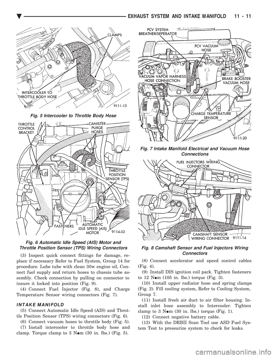
insure it locked into position (Fig. 9). (4) Connect Fuel Injector (Fig. 8), and Charge
Temperature Sensor wiring connectors (Fig. 7).
INTAKE MANIFOLD
(5) Connect Automatic Idle Speed (AIS) and Throt-
tle Position Sensor (TPS) wiring connectors (Fig. 6). (6) Connect vacuum hoses to throttle body (Fig. 5).
(7) Install intercooler to throttle body hose and
clamp. Torque clamp to 3 N Im (30 in. lbs.) (Fig. 5). (8) Connect accelerator and speed control cables
(Fig. 4). (9) Install DIS ignition coil pack. Tighten fasteners
to 12 N Im (105 in. lbs.) torque (Fig. 3).
(10) Install upper radiator hose and spring clamps
(Fig. 2). Fill cooling system, Refer to Cooling System,
Group 7. (11) Install fresh air duct to air filter housing. In-
stall inlet hose assembly to Intercooler. Tighten
clamp to 3 N Im (30 in. lbs.) torque (Fig. 1).
(12) Connect negative battery cable.
(13) With the DRBII Scan Tool use ASD Fuel Sys-
tem Test to pressurize system to check for leaks.
Fig. 5 Intercooler to Throttle Body Hose
Fig. 6 Automatic Idle Speed (AIS) Motor and
Throttle Position Sensor (TPS) Wiring Connectors
Fig. 7 Intake Manifold Electrical and Vacuum Hose Connections
Fig. 8 Camshaft Sensor and Fuel Injectors WiringConnectors
Ä EXHAUST SYSTEM AND INTAKE MANIFOLD 11 - 11
Page 1782 of 2438
once the system has entered closed loop. Refer to
Modes of Operation in this section for an explanation
of closed loop operation.
NON-MONITORED CIRCUITS
The PCM does not monitor the following circuits,
systems and conditions that could have malfunctions
that result in driveability problems. Diagnostic trou-
ble codes may not be displayed for these conditions.
However, problems with these systems may cause di-
agnostic trouble codes to be displayed for other sys-
tems. For example, a fuel pressure problem will not
register a fault directly, but could cause a rich or
lean condition. This could cause an oxygen sensor
fault to be stored in the PCM. Fuel Pressure - Fuel pressure is controlled by the
fuel pressure regulator. The PCM cannot detect a
clogged fuel pump inlet filter, clogged in-line fuel fil-
ter, or a pinched fuel supply or return line. However,
these could result in a rich or lean condition causing
an oxygen sensor fault. Secondary Ignition Circuit - The PCM cannot
detect an inoperative ignition coil, fouled or worn
spark plugs, ignition cross firing, or open spark plug
cables. Engine Timing - The PCM cannot detect an incor-
rectly indexed timing chain, camshaft sprocket and
crankshaft sprocket. The PCM also cannot detect an
incorrectly indexed distributor. However, these could
result in a rich or lean condition causing an oxygen
sensor fault to be stored in the PCM. Cylinder Compression - The PCM cannot detect
uneven, low, or high engine cylinder compression. Exhaust System
- The PCM cannot detect a
plugged, restricted or leaking exhaust system. Fuel Injector Malfunctions - The PCM cannot
determine if the fuel injector is clogged, the pintle is
sticking or the wrong injector is installed. However,
these could result in a rich or lean condition causing
an oxygen sensor fault to be stored in the PCM. Excessive Oil Consumption - Although the PCM
monitors the exhaust stream oxygen content through
the oxygen sensor when the system is in closed loop,
it cannot determine excessive oil consumption. Throttle Body Air Flow - The PCM cannot detect
a clogged or restricted air cleaner inlet or filter ele-
ment. Evaporative System - The PCM will not detect a
restricted, plugged or loaded evaporative purge can-
ister. Vacuum Assist - Leaks or restrictions in the vac-
uum circuits of vacuum assisted engine control sys-
tem devices are not monitored by the PCM. However,
these could result in a MAP sensor fault being stored
in the PCM. PCM System Ground - The PCM cannot deter-
mine a poor system ground. However, a diagnostic
trouble code may be generated as a result of this con-
dition. PCM Connector Engagement - The PCM cannot
determine spread or damaged connector pins. How-
ever, a diagnostic trouble code may be generated as a
result of this condition.
HIGH AND LOW LIMITS
The powertrain control module (PCM) compares in-
put signal voltages from each input device with es-
tablished high and low limits that are programmed
into it for that device. If the input voltage is not
within specifications and other diagnostic trouble
code criteria are met, a diagnostic trouble code will
be stored in memory. Other diagnostic trouble code
criteria might include engine RPM limits or input
voltages from other sensors or switches that must be
present before a fault condition can be verified.
DIAGNOSTIC TROUBLE CODE DESCRIPTION
When a diagnostic trouble code appears, it indi-
cates the powertrain control module (PCM) has rec-
ognized an abnormal condition in the system.
Diagnostic trouble codes can be obtained from the
malfunction indicator lamp (instrument panel Check
Engine lamp) on the Instrument Panel or from the
DRBII scan tool. Diagnostic trouble codes indicate
the results of a failure but do not identify the failed
component directly.
Fig. 3 Data Link Connector LocationÐAG and AJ Vehicles
14 - 42 FUEL SYSTEMS Ä
Page 1795 of 2438
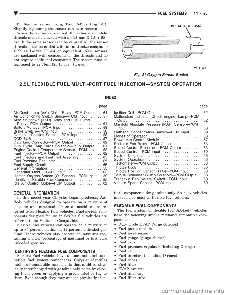
(2) Remove sensor using Tool C-4907 (Fig. 21).
Slightly tightening the sensor can ease removal. When the sensor is removed, the exhaust manifold
threads must be cleaned with an 18 mm X 1.5 + 6E
tap. If the same sensor is to be reinstalled, the sensor
threads must be coated with an anti-seize compound
such as Loctite 771-64 or equivalent. New sensors
are packaged with compound on the threads and do
not require additional compound. The sensor must be
tightened to 27 N Im (20 ft. lbs.) torque.
2.5L FLEXIBLE FUEL MULTI-PORT FUEL INJECTIONÐSYSTEM OPERATION
INDEX
page page
Air Conditioning (A/C) Clutch RelayÐPCM Output.61
Air Conditioning Switch SenseÐPCM Input ..... 57
Auto Shutdown (ASD) Relay and Fuel Pump RelayÐPCM Output ..................... 61
Battery VoltageÐPCM Input ................ 58
Brake SwitchÐPCM Input .................. 58
Camshaft Position SensorÐPCM Input ........ 58
CCD BUS .............................. 57
Data Link ConnectorÐPCM Output ........... 62
Duty Cycle Evap Purge SolenoidÐPCM Output . 61
Engine Coolant Temperature SensorÐPCM Input . 58
Fuel InjectorÐPCM Output ................. 62
Fuel Injectors and Fuel Rail Assembly ......... 65
Fuel Pressure Regulator ................... 65
Fuel Supply Circuit ....................... 65
General Information ....................... 55
Generator FieldÐPCM Output ............... 62
Heated Oxygen Sensor (O
2Sensor)ÐPCM Input . 59
Identifying Flexible Fuel Components .......... 55
Idle Air Control MotorÐPCM Output .......... 62 Ignition CoilÐPCM Output
.................. 62
Malfunction Indicator (Check Engine) LampÐPCM Output ............................... 62
Manifold Absolute Pressure (MAP) SensorÐPCM Input ................................ 58
Methanol Concentration SensorÐPCM Input .... 59
Modes of Operation ....................... 63
Powertrain Control Module ................. 57
Radiator Fan RelayÐPCM Output ............ 63
Speed Control SolenoidsÐPCM Output ........ 63
Speed ControlÐPCM Input ................. 60
System Diagnosis ........................ 56
System Operation ........................ 56
TachometerÐPCM Output .................. 63
Throttle Body ............................ 65
Throttle Position Sensor (TPS)ÐPCM Input ..... 60
Torque Converter Clutch SolenoidÐPCM Output . 63
Transaxle Park/Neutral SwitchÐPCM Input ..... 60
Vehicle Speed SensorÐPCM Input ........... 60
GENERAL INFORMATION
In this model year Chrysler began producing AA-
Body vehicles designed to operate on a mixture of
gasoline and methanol. These automobiles are re-
ferred to as Flexible Fuel vehicles. Fuel system com-
ponents designed for use in flexible fuel vehicles are
referred to as Methanol Compatible. Flexible fuel vehicles can operate on a mixture of
up to 85 percent methanol, 15 percent unleaded gas-
oline. These vehicles also operate on mixtures con-
taining a lower percentage of methanol or just pure
unleaded gasoline.
IDENTIFYING FLEXIBLE FUEL COMPONENTS
Flexible Fuel vehicles have unique methanol com-
patible fuel system components. Chrysler identifies
methanol compatible components that could be phys-
ically interchanged with gasoline only parts by color-
ing them green or applying a green label or tag to
them. Even though they may appear physically iden- tical, components for gasoline only AA-body vehicles
must not be used on flexible fuel vehicles.
FLEXIBLE FUEL COMPONENTS
The fuel system of flexible fuel AA-body vehicles
have the following unique methanol compatible com-
ponents.
² Duty Cycle EVAP Purge Solenoid
² Fuel pump module
² Fuel level sensor
² Fuel gauge (gauge cluster).
² Fuel tank
² Fuel pressure regulator (including O-rings)
² Fuel rail
² Fuel injectors (including O-rings)
² Fuel tubes
² Fuel filter
² EVAP canister
² Fuel filler cap
² Fuel filler tube
Fig. 21 Oxygen Sensor Socket
Ä FUEL SYSTEMS 14 - 55