1993 CHEVROLET PLYMOUTH ACCLAIM oil filter
[x] Cancel search: oil filterPage 1574 of 2438
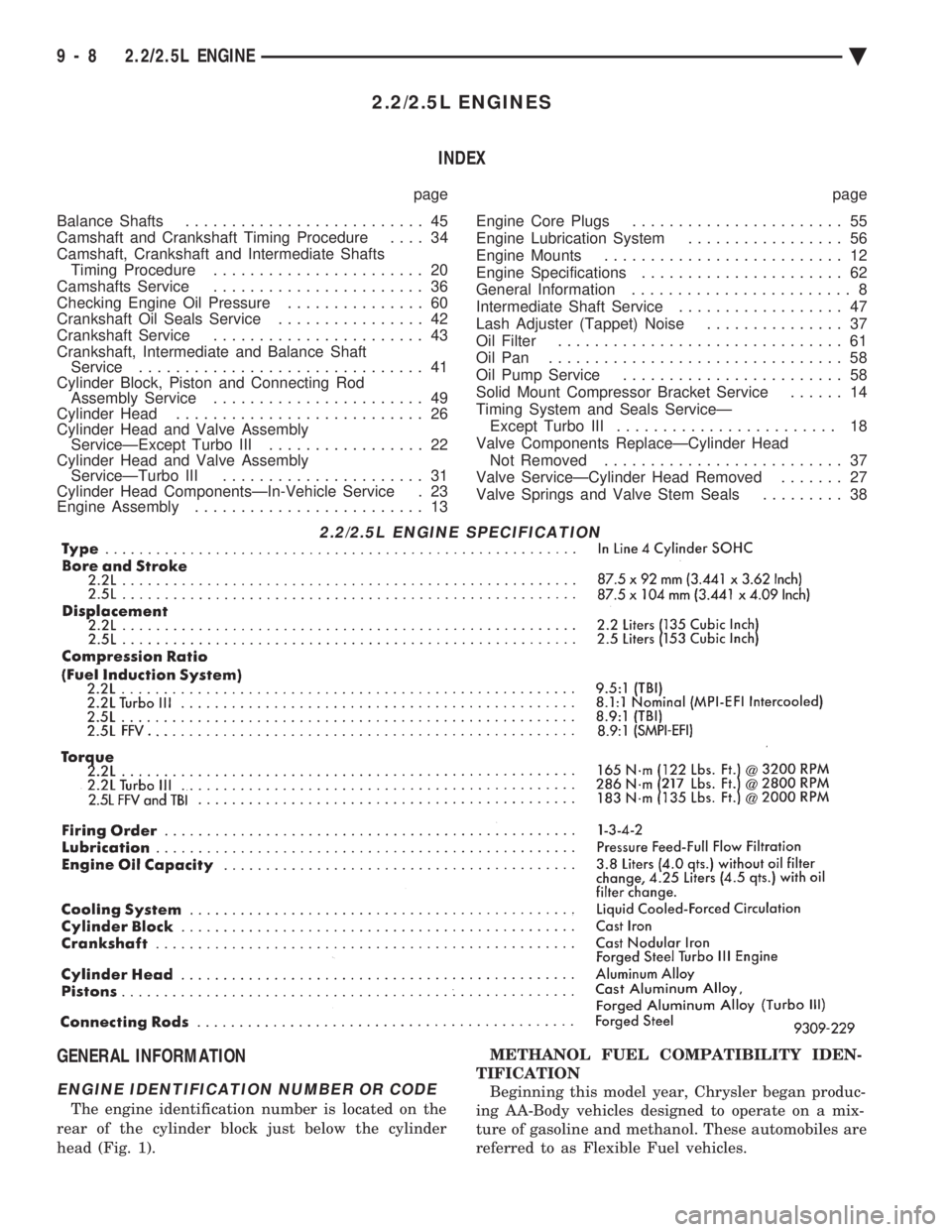
2.2/2.5L ENGINES INDEX
page page
Balance Shafts .......................... 45
Camshaft and Crankshaft Timing Procedure .... 34
Camshaft, Crankshaft and Intermediate Shafts Timing Procedure ....................... 20
Camshafts Service ....................... 36
Checking Engine Oil Pressure ............... 60
Crankshaft Oil Seals Service ................ 42
Crankshaft Service ....................... 43
Crankshaft, Intermediate and Balance Shaft Service ............................... 41
Cylinder Block, Piston and Connecting Rod Assembly Service ....................... 49
Cylinder Head ........................... 26
Cylinder Head and Valve Assembly ServiceÐExcept Turbo III ................. 22
Cylinder Head and Valve Assembly ServiceÐTurbo III ...................... 31
Cylinder Head ComponentsÐIn-Vehicle Service . 23
Engine Assembly ......................... 13 Engine Core Plugs
....................... 55
Engine Lubrication System ................. 56
Engine Mounts .......................... 12
Engine Specifications ...................... 62
General Information ........................ 8
Intermediate Shaft Service .................. 47
Lash Adjuster (Tappet) Noise ............... 37
Oil Filter ............................... 61
Oil Pan ................................ 58
Oil Pump Service ........................ 58
Solid Mount Compressor Bracket Service ...... 14
Timing System and Seals ServiceÐ Except Turbo III ........................ 18
Valve Components ReplaceÐCylinder Head Not Removed .......................... 37
Valve ServiceÐCylinder Head Removed ....... 27
Valve Springs and Valve Stem Seals ......... 38
GENERAL INFORMATION
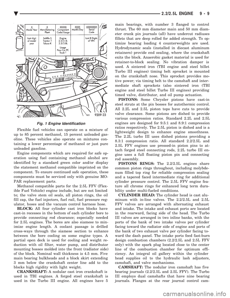
ENGINE IDENTIFICATION NUMBER OR CODE
The engine identification number is located on the
rear of the cylinder block just below the cylinder
head (Fig. 1). METHANOL FUEL COMPATIBILITY IDEN-
TIFICATION Beginning this model year, Chrysler began produc-
ing AA-Body vehicles designed to operate on a mix-
ture of gasoline and methanol. These automobiles are
referred to as Flexible Fuel vehicles.
2.2/2.5L ENGINE SPECIFICATION
9 - 8 2.2/2.5L ENGINE Ä
Page 1575 of 2438
Flexible fuel vehicles can operate on a mixture of
up to 85 percent methanol, 15 percent unleaded gas-
oline. These vehicles also operate on mixtures con-
taining a lower percentage of methanol or just pure
unleaded gasoline. Engine components which are required for safe op-
eration using fuel containing methanol alcohol are
identified by a standard green color and/or display
the statement methanol compatible imprinted on the
component. To ensure continued safe operation, these
components must be serviced only with genuine MO-
PAR replacement parts. Methanol compatible parts for the 2.5L FFV (Flex-
ible Fuel Vehicle) engine include, but are not limited
to; the valve stem oil seals, all piston rings, the oil
fill cap, the fuel injectors, fuel rail, fuel pressure reg-
ulator, hoses and the vacuum control harness hose. BLOCK: All four cylinder cast iron blocks have
cast-in recesses in the bottom of each cylinder bore to
provide connecting rod clearance; especially needed
for 2.5L engines. The bores are also siamese to min-
imize engine length. A coolant passage is drilled
cross-ways through the siamese section to enhance
between the bore cooling on some engine types. A
partial open deck is used for cooling and weight re-
duction with oil filter, water pump, and distributor
mounting bosses molded into the front (radiator side)
of the block. Nominal wall thickness is 4.5 mm. Five
main bearing bulkheads and a block skirt extending
3 mm below the crankshaft center line add to the
blocks high rigidity with light weight. CRANKSHAFT: A nodular cast iron crankshaft is
used in TBI engines. A forged steel crankshaft is
used in the Turbo III engine. All engines have 5 main bearings, with number 3 flanged to control
thrust. The 60 mm diameter main and 50 mm diam-
eter crank pin journals (all) have undercut radiuses
fillets that are deep rolled for added strength. To op-
timize bearing loading 4 counterweights are used.
Hydrodynamic seals (installed in diecast aluminum
retainers) provide end sealing, where the crankshaft
exits the block. Anaerobic gasket material is used for
retainer-to-block sealing. No vibration damper is
used. A sintered iron (TBI engine and steel billet
Turbo III engines) timing belt sprocket is mounted
on the crankshaft nose. This sprocket provides mo-
tive power; via timing belt to the camshaft and inter-
mediate shaft sprockets (also sintered iron (TBI
engine and steel billet Turbo III engines) providing
timed valve, distributor, and oil pump actuation. PISTONS: Some Chrysler pistons have cast-in
steel struts at the pin bosses for autothermic control.
All 2.2L and 2.5L piston tops have cuts to provide
valve clearance. Some pistons are dished to provide
various compression ratios. Standard 2.2L and 2.5L
engines are designed for 9.5:1 and 8.9:1 compression
ratios respectively. The 2.5L piston is dished and is a
lightweight design to enhance engine smoothness.
The 2.2L turbo III uses dished pistons providing a
8.3:1 compression ratio. All standard 2.2/2.5L and
2.5L FFV engines use pressed-in piston pins to at-
tach forged steel connecting rods, 2.2L turbo III en-
gine uses a full floating piston pin and connecting
rod assembly. PISTONS RINGS: The 2.2/2.5L engines share
common piston rings throughout, including molybde-
num filled top ring for reliable compression sealing
and a tapered faced intermediate ring for additional
cylinder pressure control. The 2.5L FFV engine fea-
ture all chrome rings for enhanced long term dura-
bility under multi-fueled conditions. CYLINDER HEAD: The cylinder head is cast alu-
minum with in-line valves. The 2.2/2.5L and 2.5L
FFV valves are arranged with alternating exhaust
and intake. The intake and exhaust ports are located
in the rearward, facing side of the head. The Turbo
III valves are arranged in two inline banks, with the
ports of the bank of two intake valves per cylinder
facing toward the radiator side of engine and ports of
the bank of two exhaust valve per cylinder facing to-
ward the dash panel. The intake ports feed fast-burn
design combustion chambers (2.2/2.5L and 2.5L FFV
only) with the spark plug located close to the center
line of the combustion chamber for optimum effi-
ciency. An integral oil gallery within the cylinder
head supplies oil to the hydraulic lash adjusters,
camshaft, and valve mechanisms. CAMSHAFT: The nodular iron camshaft has five
bearing journals (2.2/2.5L and 2.5L FFV). The Turbo
III employs dual camshafts that have nine bearing
journals. Flanges at the rear journal control cam-
Fig. 1 Engine Identification
Ä 2.2/2.5L ENGINE 9 - 9
Page 1579 of 2438
² Drive shaft distress: See Driveshafts in Suspension,
Group 2.
² Any front end structural damage (after repair).
² Insulator replacement.
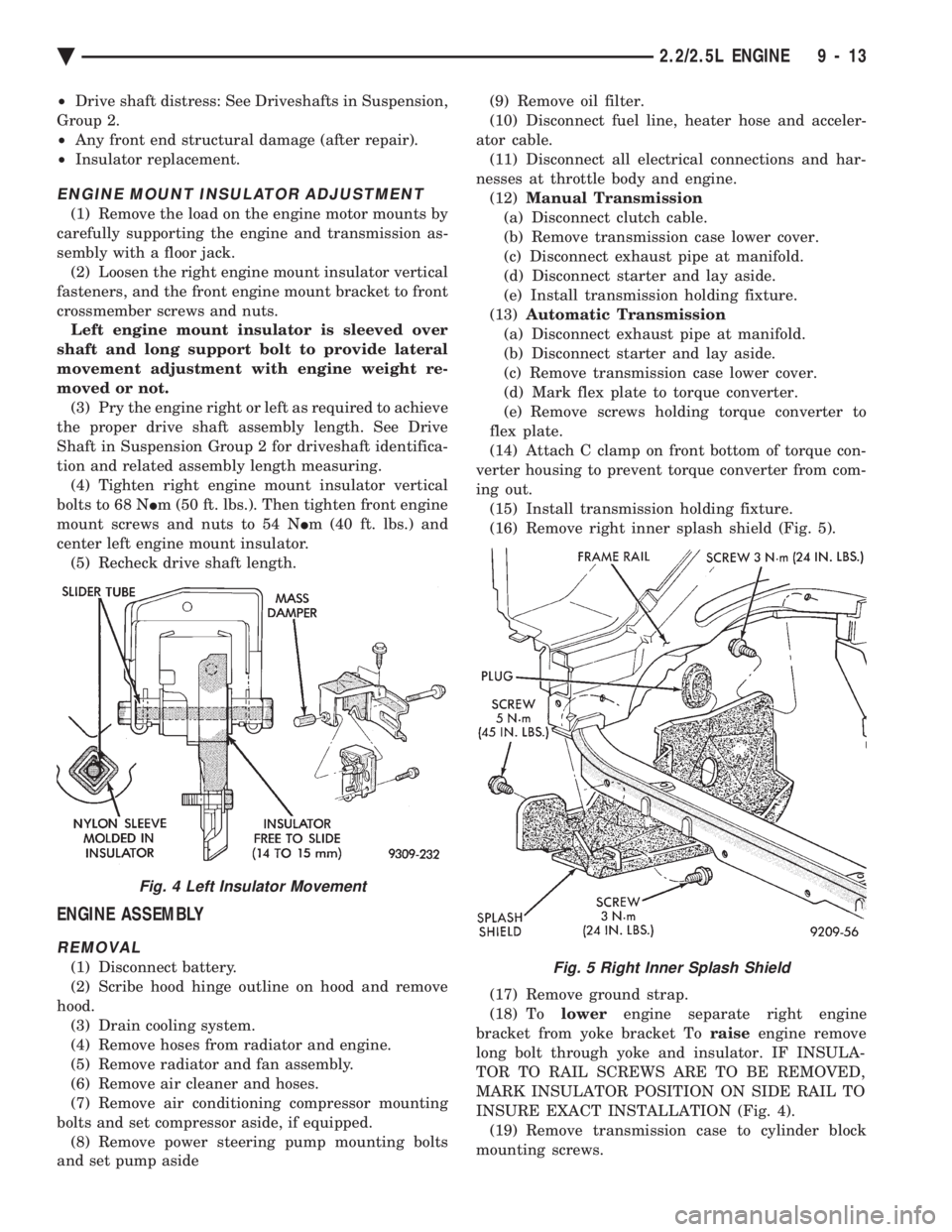
ENGINE MOUNT INSULATOR ADJUSTMENT
(1) Remove the load on the engine motor mounts by
carefully supporting the engine and transmission as-
sembly with a floor jack. (2) Loosen the right engine mount insulator vertical
fasteners, and the front engine mount bracket to front
crossmember screws and nuts. Left engine mount insulator is sleeved over
shaft and long support bolt to provide lateral
movement adjustment with engine weight re-
moved or not. (3) Pry the engine right or left as required to achieve
the proper drive shaft assembly length. See Drive
Shaft in Suspension Group 2 for driveshaft identifica-
tion and related assembly length measuring. (4) Tighten right engine mount insulator vertical
bolts to 68 N Im (50 ft. lbs.). Then tighten front engine
mount screws and nuts to 54 N Im (40 ft. lbs.) and
center left engine mount insulator. (5) Recheck drive shaft length.
ENGINE ASSEMBLY
REMOVAL
(1) Disconnect battery.
(2) Scribe hood hinge outline on hood and remove
hood. (3) Drain cooling system.
(4) Remove hoses from radiator and engine.
(5) Remove radiator and fan assembly.
(6) Remove air cleaner and hoses.
(7) Remove air conditioning compressor mounting
bolts and set compressor aside, if equipped. (8) Remove power steering pump mounting bolts
and set pump aside (9) Remove oil filter.
(10) Disconnect fuel line, heater hose and acceler-
ator cable. (11) Disconnect all electrical connections and har-
nesses at throttle body and engine. (12) Manual Transmission
(a) Disconnect clutch cable.
(b) Remove transmission case lower cover.
(c) Disconnect exhaust pipe at manifold.
(d) Disconnect starter and lay aside.
(e) Install transmission holding fixture.
(13) Automatic Transmission
(a) Disconnect exhaust pipe at manifold.
(b) Disconnect starter and lay aside.
(c) Remove transmission case lower cover.
(d) Mark flex plate to torque converter.
(e) Remove screws holding torque converter to
flex plate.
(14) Attach C clamp on front bottom of torque con-
verter housing to prevent torque converter from com-
ing out. (15) Install transmission holding fixture.
(16) Remove right inner splash shield (Fig. 5).
(17) Remove ground strap.
(18) To lowerengine separate right engine
bracket from yoke bracket To raiseengine remove
long bolt through yoke and insulator. IF INSULA-
TOR TO RAIL SCREWS ARE TO BE REMOVED,
MARK INSULATOR POSITION ON SIDE RAIL TO
INSURE EXACT INSTALLATION (Fig. 4). (19) Remove transmission case to cylinder block
mounting screws.Fig. 5 Right Inner Splash Shield
Fig. 4 Left Insulator Movement
Ä 2.2/2.5L ENGINE 9 - 13
Page 1580 of 2438
CAUTION: Make sure clutch cable has been discon-
nected. (20) Remove front engine mount screw and nut.
(21) Remove manual transmission damper.
(22) Remove left insulator through bolt from inside
wheelhouse or insulator bracket to transmission
screws. (23) Remove engine from vehicle.
INSTALLATION
(1) Install hoist to the engine and lower engine
into the engine compartment. SEE: ENGINE MOUNT RUBBER INSULATORS,
THIS GROUP. (2) Align engine mounts and install but do not
tighten until all mounting bolts have been installed.
(3) Install transmission case to cylinder block
mounting screws. Tighten to 95 N Im (70 ft. lbs.)
torque. (4) Remove engine hoist and transmission holding
fixture. (5) Install ground strap.
(6) Install right inner splash shield.
(7) Connect starter. See Electrical Group 8 for in-
stallation. (8) Connect exhaust system. See Exhaust Systems
Group 11 for installation. (9) Manual Transmission: Install transmission
case lower cover. Automatic Transmission: Remove C clamp from
torque converter housing. Align flexplate to torque
converter and install mounting screws. Tighten to 75
N Im (55 ft. lbs.) torque.
(10) Manual Transmission: Connect clutch cable.
See Clutch Group 6. (11) Install power steering pump. Refer to Cooling
System Group 7, Accessory Drive Section for belt
tension adjustment. (12) Connect fuel line, heater hose, and accelerator
cable. (13) Connect all electrical connections and har-
nesses at throttle body and engine. (14) Install oil filter. Fill engine crankcase with
proper oil to correct level. (15) Install air conditioning compressor (if
equipped). See Heater and Air Conditioning, Group
24 for installation. (16) Install air cleaner and hoses.
(17) Install radiator and shroud assembly . Install
radiator hoses. Fill cooling system. See Cooling Sys-
tem Group 7 for filling procedure. (18) Install hood.
(19) Connect battery.
(20) Start engine and run until operating temper-
ature is reached. (21) Adjust transmission linkage, if necessary.
SOLID MOUNT COMPRESSOR BRACKET SERVICE
When service procedures require solid mount
bracket removal and installation for example: cylin-
der head removal, etc., it is important that bracket
fasteners numbered 1 through 7 (Fig. 4) be removed
and installed in sequence, as instructed in Remove
and Install.
ACCESSORIES REMOVAL
(1) Remove (and install/adjust) belts,see Accessory
Drive Belts in Cooling System,Group 7. (2) Remove air conditioning compressor (in vehicle
with lines and set aside) (Fig. 6). (3) Remove generator pivot bolt and remove gener-
ator (in vehicle: turn wiring side up and disconnect,
then rotate generator, pulley end towards engine and
remove). (4) Remove air conditioner compressor belt idler.
SOLID MOUNT BRACKETÐREMOVAL (FIG. 4)
(1) Remove right engine mount yoke screw (see
Engine Remove Fig. 3) securing engine mount sup-
port strut to engine mount bracket. (2) Remove five side mounting bolts #1, #4 , #5,
#6, and #7 (Fig. 4). (3) Remove front mounting nut, #2, and remove
front bolt #3*. (4) Remove front mounting bolt and strut, rotate
solid mount bracket away from engine and slide
bracket on stud until #2 nut mounting stud until
free. Remove spacer from stud.
SOLID MOUNT BRACKETÐINSTALLATION
(1) Put spacer onto stud, then install bracket on
front (#2 nut) mounting stud and slide bracket over
timing belt cover into position. (2) Loosen assembly bracket to engine fasteners
(numbered #1 through #7 in Fig. 6). (3)
CAUTION: Fasteners MUST BE TIGHTENED IN SE-
QUENCE and to specified torque as follows :
² First Bolt #1 to 3.3 N Im (30 in. lbs.)
² Second Nut #2 and Bolt #3 to 54 N Im (40 ft. lbs.).
² Third Bolts #1 (second tightening) #4 and #5 to
54 N Im (40 ft. lbs.).
² Fourth Bolts #6 and #7 to 54 N Im (40 ft. lbs.).
(4) Install generator and compressor. Tighten com-
pressor mounting bracket bolts to 54 N Im (40 ft.
lbs.).
SOLID MOUNT COMPRESSOR BRACKET SERVICEÐTURBO III ENGINE
REMOVAL
(1) Disconnect negative battery cable
9 - 14 2.2/2.5L ENGINE Ä
Page 1624 of 2438
OIL PAN
A formed steel oil pan provides lower engine pro-
tection as well as serving as the engine oil reservoir
(Fig. 1). Pan side flanges to block are sealed with
gaskets. The oil pickup tube for some 2.2L engines
have a circular strainer and cover. The 2.5L engine
pickup is also unsupported and the lower end has a
box type strainer (Fig. 4).
PRESSURE LUBRICATION
Oil drawn up through the pickup tube is pressur-
ized by the pump and routed through the full flow
filter to the main oil gallery running the length of
the cylinder block (Fig. 2). Modified oil pickup, pump
and check valve provide increased oil flow to the
main oil gallery.
MAIN/ROD BEARINGS
A diagonal hole in each bulkhead feeds oil to each
main bearing. Drilled passages within the crankshaft
route oil from main bearing journals to crankpin
journals.
ACCESSORY SHAFT
Two separate holes supply the accessory shaft for
the N/A engines. For Turbo III engines there is a slot
in the rear shaft bushing that squirts oil onto the
oil pump drive gears (Fig. 2).
BALANCE SHAFTS
The engine balance shafts are lubricated by an ad-
ditional hole that interconnects a passage in one leg
of the balance shaft carrier to route oil down to the
carrier oil gallery. This gallery directly supplies the
balance shafts front bearings and internal machined
passages in the shafts routes oil from front to rear
shaft bearing journals.
TURBOCHARGER (WHERE EQUIPPED)
If turbocharger equipped, pressurized oil from the
main gallery to sending unit hex fitting is piped from
the fitting to the turbocharger bearing housing.
From the housing a hose and tube connection to a
machined hole in the block provides drainback.
CAMSHAFT/HYDRAULIC LIFTERS
A vertical hole at the number five bulkhead routes
pressurized oil through a restrictor up past a cylinder
head bolt to an oil gallery running the length of the
cylinder head. For 2.2/2.5L and 2.5L FFV engines
hydraulic adjusters are supplied directly from this
gallery while diagonal holes supply oil to the cam-
shaft journals. The camshaft journals are partially
slotted to allow a predetermined amount of pressur-
ized oil to pass into the bearing cap cavities with
small holes directed to spray lubricate the camshaft
lobes. For Turbo III engines oil is supplied thru oil
galleries in the head to the camshafts and rocker arm shafts which feed oil to the lash adjusters. Oil is
feed thru the rocker arms to lubricate the rollers and
the camshaft lobes.
SPLASH LUBRICATION
Oil returning to the pan from pressurized compo-
nents supplies lubrication to the valve stems. Cylinder
bores and wrist pins are splash lubricated from di-
rected holes in the connecting rods.
OIL PAN
REMOVAL
(1) Drain engine oil and remove oil pan.
(2) Clean oil pan and all gasket surfaces.
OIL PAN RAIL TO BLOCK SEALING
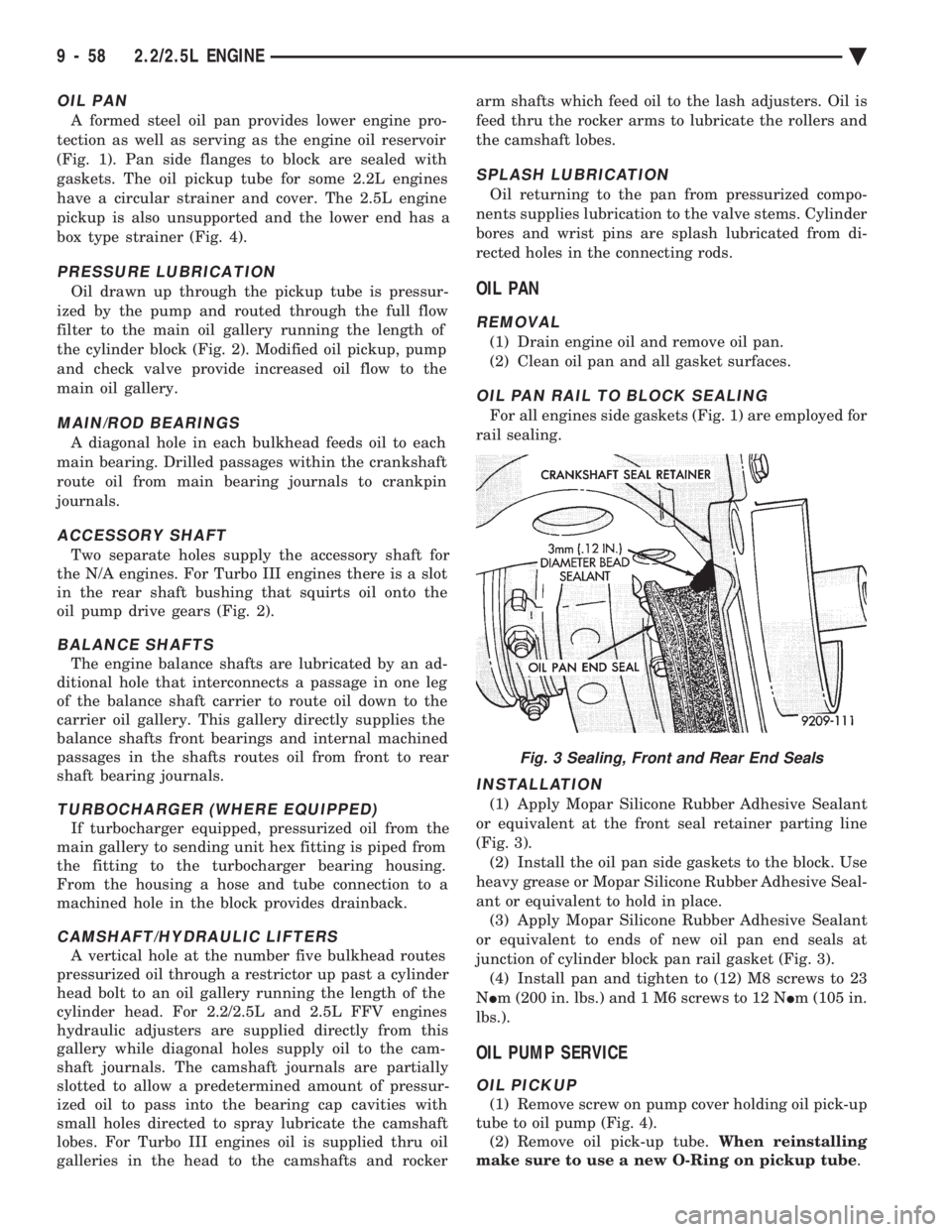
For all engines side gaskets (Fig. 1) are employed for
rail sealing.
INSTALLATION
(1) Apply Mopar Silicone Rubber Adhesive Sealant
or equivalent at the front seal retainer parting line
(Fig. 3). (2) Install the oil pan side gaskets to the block. Use
heavy grease or Mopar Silicone Rubber Adhesive Seal-
ant or equivalent to hold in place. (3) Apply Mopar Silicone Rubber Adhesive Sealant
or equivalent to ends of new oil pan end seals at
junction of cylinder block pan rail gasket (Fig. 3). (4) Install pan and tighten to (12) M8 screws to 23
N Im (200 in. lbs.) and 1 M6 screws to 12 N Im (105 in.
lbs.).
OIL PUMP SERVICE
OIL PICKUP
(1) Remove screw on pump cover holding oil pick-up
tube to oil pump (Fig. 4). (2) Remove oil pick-up tube. When reinstalling
make sure to use a new O-Ring on pickup tube .
Fig. 3 Sealing, Front and Rear End Seals
9 - 58 2.2/2.5L ENGINE Ä
Page 1627 of 2438
(3) Oil Pressure: Curb Idle25 kPa (4 psi) mini-
mum 3000 RPM 170-550 kPa (25-80 psi).
OIL FILTER
ANTI-DRAIN BACK VALVE
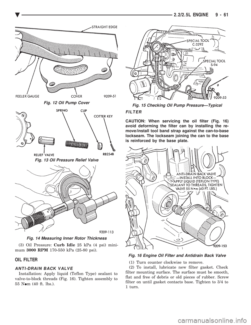
Installation: Apply liquid (Teflon Type) sealant to
valve-to-block threads (Fig. 16). Tighten assembly to
55 N Im (40 ft. lbs.).
FILTER
CAUTION: When servicing the oil filter (Fig. 16)
avoid deforming the filter can by installing the re-
move/install tool band strap against the can-to-base
lockseam. The lockseam joining the can to the base
is reinforced by the base plate.
(1) Turn counter clockwise to remove.
(2) To install, lubricate new filter gasket. Check
filter mounting surface. The surface must be smooth,
flat and free of debris or old pieces of rubber. Screw
filter on until gasket contacts base. Tighten to 3/4 to
1 turn.
Fig. 12 Oil Pump Cover
Fig. 13 Oil Pressure Relief Valve
Fig. 14 Measuring Inner Rotor Thickness
Fig. 15 Checking Oil Pump PressureÐTypical
Fig. 16 Engine Oil Filter and Antidrain Back Valve
Ä 2.2/2.5L ENGINE 9 - 61
Page 1632 of 2438
3.0L ENGINE INDEX
page page
Accessory Drive Belt Service ................ 70
Auto Lash Adjuster ....................... 75
Camshaft Service ........................ 76
Checking Engine Oil Pressure ............... 93
Crankshaft and Cylinder Block, Assembly Service . 86
Cylinder Block ........................... 89
Cylinder Head ........................... 78
Cylinder Head and Camshaft Service ......... 75
Engine Assembly ......................... 69
Engine Lubrication System ................. 91
Engine Mounts .......................... 68 Engine Specifications
..................... 95
General Information ....................... 66
Oil Filter and Bracket ..................... 94
Oil Pan ................................ 92
Oil Pump Service ........................ 92
Piston and Connecting Rod Assembly Service . . . 82
Timing Belt InspectionÐIn Vehicle ............ 72
Timing Belt Service ....................... 72
Valve Service ........................... 80
GENERAL INFORMATION
ENGINE IDENTIFICATION NUMBER OR CODE
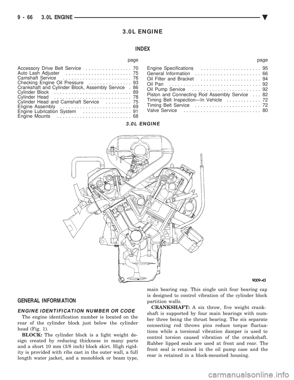
The engine identification number is located on the
rear of the cylinder block just below the cylinder
head (Fig. 1). BLOCK: The cylinder block is a light weight de-
sign created by reducing thickness in many parts
and a short 10 mm (3/8 inch) block skirt. High rigid-
ity is provided with ribs cast in the outer wall, a full
length water jacket, and a monoblock or beam type, main bearing cap. This single unit four bearing cap
is designed to control vibration of the cylinder block
partition walls.
CRANKSHAFT: A six throw, five weight crank-
shaft is supported by four main bearings with num-
ber three being the thrust bearing. The six separate
connecting rod throws pins reduce torque fluctua-
tions while a torsional vibration damper is used to
control torsion caused vibration of the crankshaft.
Rubber lipped seals are used at front and rear. The
front seal is retained in the oil pump case and the
rear is retained in a block-mounted housing.
3.0L ENGINE
9 - 66 3.0L ENGINE Ä
Page 1657 of 2438
(clearance between piston O.D. and cylinder) minus
0.02 mm which is the boring margin. (3) Bore all cylinders to calculated boring finish di-
mension. Then bore the final finish dimension (piston
O.D. plus cylinder clearance). (4) Check clearance between piston and cylinder,
clearance should be 0.03 to 0.05 mm (.0012 to .002
inch).
ENGINE LUBRICATION SYSTEM
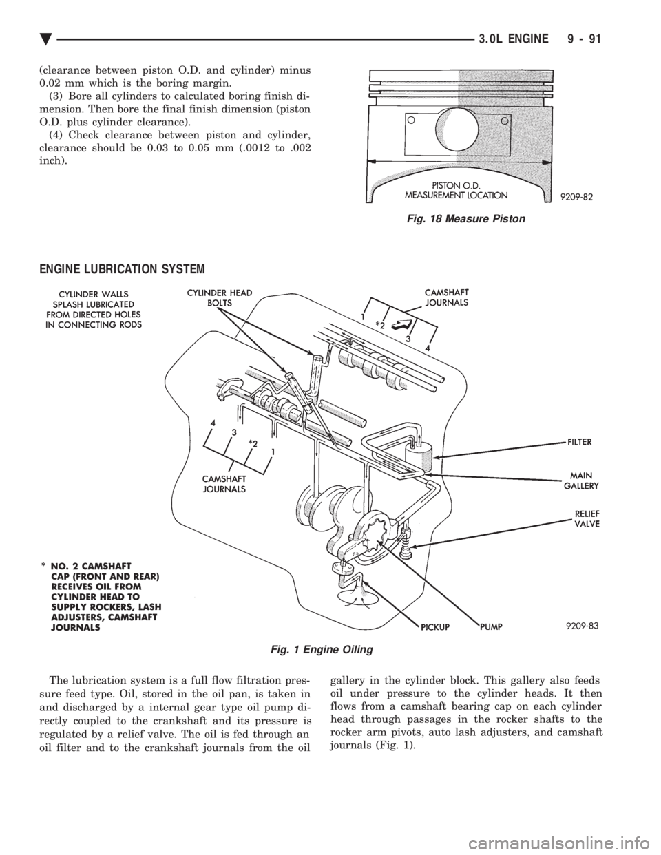
The lubrication system is a full flow filtration pres-
sure feed type. Oil, stored in the oil pan, is taken in
and discharged by a internal gear type oil pump di-
rectly coupled to the crankshaft and its pressure is
regulated by a relief valve. The oil is fed through an
oil filter and to the crankshaft journals from the oil gallery in the cylinder block. This gallery also feeds
oil under pressure to the cylinder heads. It then
flows from a camshaft bearing cap on each cylinder
head through passages in the rocker shafts to the
rocker arm pivots, auto lash adjusters, and camshaft
journals (Fig. 1).
Fig. 18 Measure Piston
Fig. 1 Engine Oiling
Ä 3.0L ENGINE 9 - 91