1993 CHEVROLET PLYMOUTH ACCLAIM oil filter
[x] Cancel search: oil filterPage 2012 of 2438
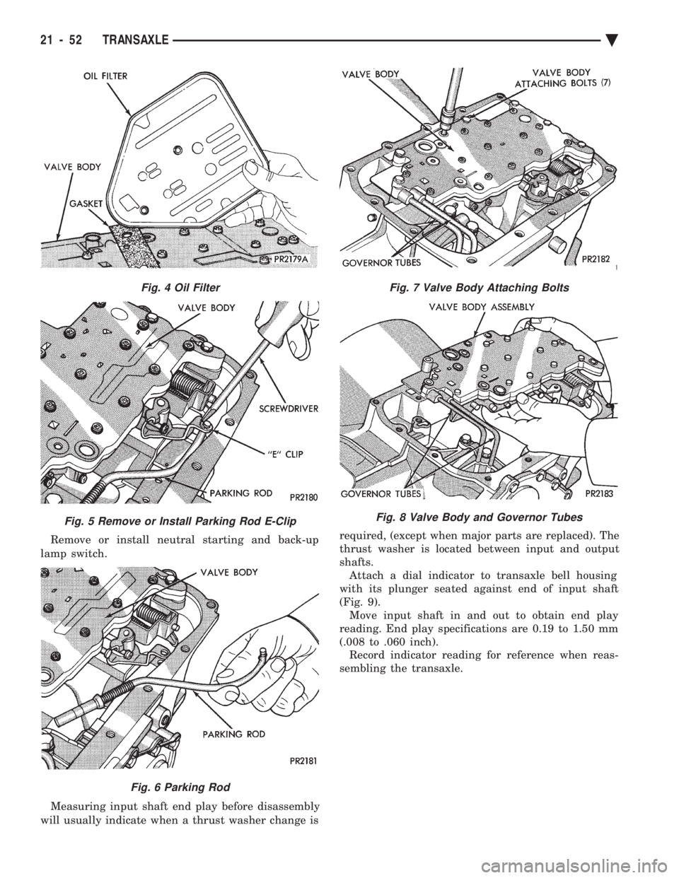
Remove or install neutral starting and back-up
lamp switch.
Measuring input shaft end play before disassembly
will usually indicate when a thrust washer change is required, (except when major parts are replaced). The
thrust washer is located between input and output
shafts. Attach a dial indicator to transaxle bell housing
with its plunger seated against end of input shaft
(Fig. 9). Move input shaft in and out to obtain end play
reading. End play specifications are 0.19 to 1.50 mm
(.008 to .060 inch). Record indicator reading for reference when reas-
sembling the transaxle.
Fig. 4 Oil Filter
Fig. 5 Remove or Install Parking Rod E-Clip
Fig. 6 Parking Rod
Fig. 7 Valve Body Attaching Bolts
Fig. 8 Valve Body and Governor Tubes
21 - 52 TRANSAXLE Ä
Page 2045 of 2438
41TE FOUR SPEED AUTOMATIC TRANSAXLE INDEX
page page
41TE Transaxle General Diagnosis ........... 88
Aluminum Thread Repair ................... 98
Bearing Adjustment Procedure .............. 141
Clutch Air Pressure Tests .................. 95
Coolers and Tubes Reverse Flushing ......... 98
Diagnosis Chart ``B'' ....................... 90
Diagnosis Trouble Code Chart ``A'' ............ 89
Differential Repair ....................... 136
Fluid and Filter Changes ................... 93
Fluid Drain and Refill ..................... 93
Fluid Leakage-Torque Converter Housing Area . . 97
Fluid Level and Condition .................. 93
Gearshift Linkage Adjustment ............... 98
General Information ....................... 85
Hydraulic Pressure Tests ................... 94
Input Clutches-Recondition ................ 121
Oil Cooler Flow Check .................... 99 Oil Pump Seal Replace
................... 136
Park/Neutral Position Switch ............... 102
Pinion Factor Procedure .................. 104
Road Test .............................. 93
Selection of Lubricant ..................... 93
Solenoid Assembly-Replace ................ 101
Special Additives ......................... 93
Speed Sensor-Input ...................... 102
Speed Sensor-Output .................... 103
Torque Converter Clutch Break-In Procedure . . . 104
Transaxle Quick Learn Procedure ........... 103
Transaxle Recondition .................... 105
Transaxle Removal and Installation ........... 99
Transmission Control Module ............... 103
Transmission Range Switch ................ 102
Valve Body-Recondition ................... 132
GENERAL INFORMATION
The 41TE four-speed FWD transaxle uses fully-
adaptive controls. Adaptive controls are those which
perform their functions based on real-time feedback
sensor information. The transaxle uses hydraulically
applied clutches to shift a planetary gear train.
TRANSAXLE IDENTIFICATION
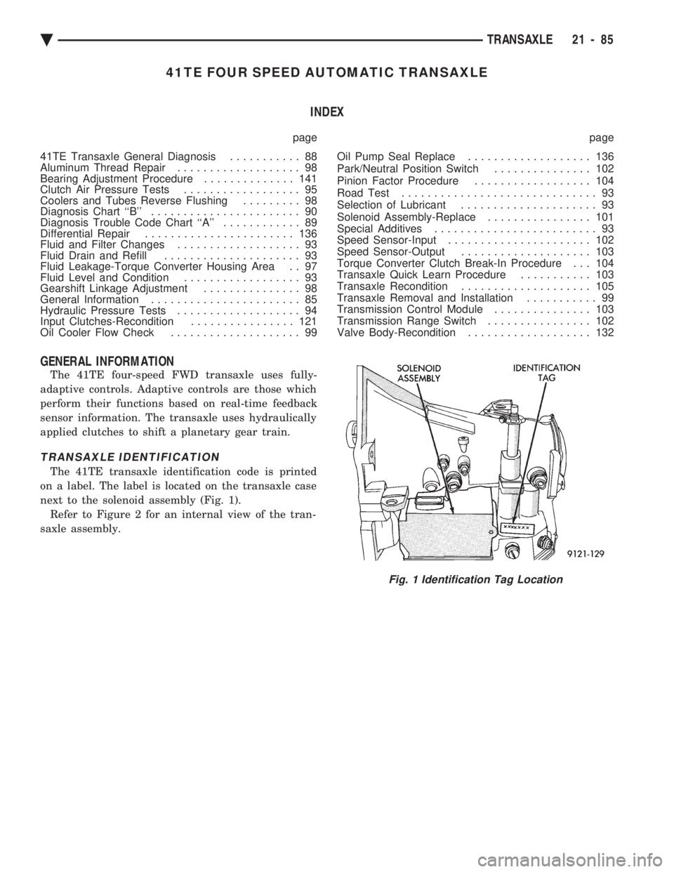
The 41TE transaxle identification code is printed
on a label. The label is located on the transaxle case
next to the solenoid assembly (Fig. 1). Refer to Figure 2 for an internal view of the tran-
saxle assembly.
Fig. 1 Identification Tag Location
Ä TRANSAXLE 21 - 85
Page 2053 of 2438
FLUID LEVEL AND CONDITION
The transmission and differential sump have a
common oil sump with a communicating opening
between the two. The torque converter fills in both the PPark and N
Neutral positions. Place the selector lever in PPark to
check the fluid level. The engine should be running
at idle speed for at least one minute, with the
vehicle on level ground. This will assure com-
plete oil level stabilization between differential
and transmission. The fluid should be at normal
operating temperature (approximately 82 C. or 180 F.).
The fluid level is correct if it is in the HOTregion
(cross-hatched area) on the oil level indicator. Low fluid level can cause a variety of conditions
because it allows the pump to take in air along with the
fluid. As in any hydraulic system, air bubbles make the
fluid spongy, therefore, pressures will be low and build
up slowly. Improper filling can also raise the fluid level too
high. When the transaxle has too much fluid, the gears
churn up foam and cause the same conditions which
occur with a low fluid level. In either case, the air bubbles can cause over heat-
ing, fluid oxidation, and varnishing, which can inter-
fere with normal valve, clutch, and accumulator opera-
tion. Foaming can also result in fluid escaping from the
transaxle vent where it may be mistaken for a leak. Along with fluid level, it is important to check the
condition of the fluid. When the fluid smells burned,
and is contaminated with metal or friction material
particles, a complete transaxle overhaul is needed. Be
sure to examine the fluid on the dipstick closely. If
there is any doubt about its condition, drain out a
sample for a double check. After the fluid has been checked, seat the dipstick
fully to seal out water and dirt.
SELECTION OF LUBRICANT
It is important that the proper lubricant be used in
the 41TE transaxle. MOPAR tATF PLUS (Automatic
Transmission FluidÐtype 7176) should be used to aid
in assuring optimum transmission performance. Flu-
ids of the type labeled DEXRON II Automatic Trans-
mission Fluid are not recommended . DEXRON II
can be used only if the recommended fluid is not
available. If more than a small amount of DEXRON II
is used shudder or shift quality problems may result. It
is important that the transmission fluid be maintained
at the prescribed level using the recommended fluids.
SPECIAL ADDITIVES
Chrysler Corporation does not recommend the addi-
tion of any fluids to the transaxle, other than the
automatic transmission fluid listed above. An excep- tion to this policy is the use of special dyes to aid in
detecting fluid leaks. The use of transmission sealers
should be avoided, since they may adversely affect
seals.
FLUID AND FILTER CHANGES
When the factory fill fluid is changed, only fluids
labeled MOPAR tATF PLUS (Automatic Transmis-
sion fluid) Type 7176 should be used. A filter change
should be made at the time of the oil change. Also
the magnet (on the inside of the oil pan) should be
cleaned with a clean, dry cloth. If the transaxle is disassembled for any reason, the
fluid and filter should be changed.
FLUID DRAIN AND REFILL
(1) Raise vehicle on a hoist (See Lubrication,
Group 0). Place a drain container with a large open-
ing, under transaxle oil pan. (2) Loosen pan bolts and tap the pan at one corner
to break it loose allowing fluid to drain, then remove
the oil pan. (3) Install a new filter and O-ring on bottom of the
valve body. (4) Clean the oil pan and magnet. Reinstall pan
using new MOPAR tAdhesive Sealant. Tighten oil
pan bolts to 19 N Im (165 in. lbs.).
(5) Pour four quarts of MOPAR tATF PLUS (Au-
tomatic Transmission Fluid) Type 7176 through the
fill tube. (6) Start engine and allow to idle for at least one
minute. Then, with parking and service brakes ap-
plied, move selector lever momentarily to each posi-
tion, ending in the park or neutral position. (7) Add sufficient fluid to bring level to 1/8 inch
below the ADD mark. Recheck fluid level after transaxle is at normal op-
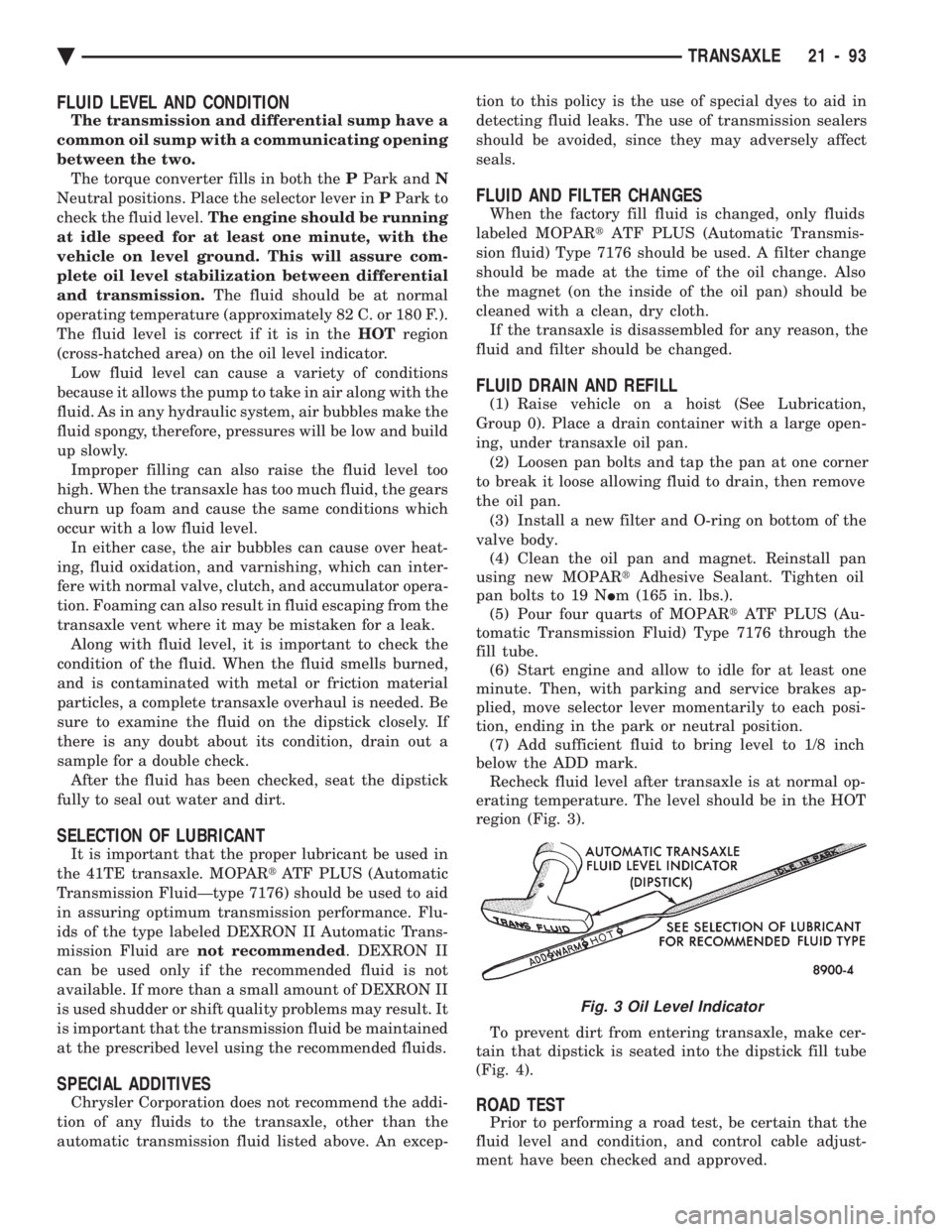
erating temperature. The level should be in the HOT
region (Fig. 3).
To prevent dirt from entering transaxle, make cer-
tain that dipstick is seated into the dipstick fill tube
(Fig. 4).
ROAD TEST
Prior to performing a road test, be certain that the
fluid level and condition, and control cable adjust-
ment have been checked and approved.
Fig. 3 Oil Level Indicator
Ä TRANSAXLE 21 - 93
Page 2055 of 2438
(5) This test checks pump output, pressure regula-
tion and condition of the low/reverse clutch hydraulic
circuit and shift schedule.
TEST TWO-SELECTOR IN DRIVE 2ND GEAR
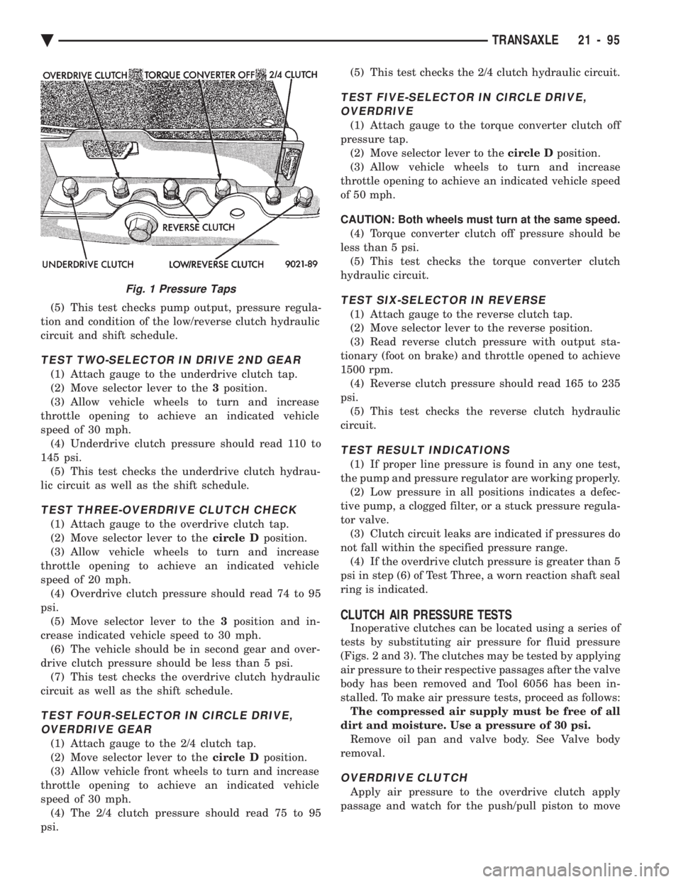
(1) Attach gauge to the underdrive clutch tap.
(2) Move selector lever to the 3position.
(3) Allow vehicle wheels to turn and increase
throttle opening to achieve an indicated vehicle
speed of 30 mph. (4) Underdrive clutch pressure should read 110 to
145 psi. (5) This test checks the underdrive clutch hydrau-
lic circuit as well as the shift schedule.
TEST THREE-OVERDRIVE CLUTCH CHECK
(1) Attach gauge to the overdrive clutch tap.
(2) Move selector lever to the circle Dposition.
(3) Allow vehicle wheels to turn and increase
throttle opening to achieve an indicated vehicle
speed of 20 mph. (4) Overdrive clutch pressure should read 74 to 95
psi. (5) Move selector lever to the 3position and in-
crease indicated vehicle speed to 30 mph. (6) The vehicle should be in second gear and over-
drive clutch pressure should be less than 5 psi. (7) This test checks the overdrive clutch hydraulic
circuit as well as the shift schedule.
TEST FOUR-SELECTOR IN CIRCLE DRIVE, OVERDRIVE GEAR
(1) Attach gauge to the 2/4 clutch tap.
(2) Move selector lever to the circle Dposition.
(3) Allow vehicle front wheels to turn and increase
throttle opening to achieve an indicated vehicle
speed of 30 mph. (4) The 2/4 clutch pressure should read 75 to 95
psi. (5) This test checks the 2/4 clutch hydraulic circuit.
TEST FIVE-SELECTOR IN CIRCLE DRIVE,
OVERDRIVE
(1) Attach gauge to the torque converter clutch off
pressure tap. (2) Move selector lever to the circle Dposition.
(3) Allow vehicle wheels to turn and increase
throttle opening to achieve an indicated vehicle speed
of 50 mph.
CAUTION: Both wheels must turn at the same speed. (4) Torque converter clutch off pressure should be
less than 5 psi. (5) This test checks the torque converter clutch
hydraulic circuit.
TEST SIX-SELECTOR IN REVERSE
(1) Attach gauge to the reverse clutch tap.
(2) Move selector lever to the reverse position.
(3) Read reverse clutch pressure with output sta-
tionary (foot on brake) and throttle opened to achieve
1500 rpm. (4) Reverse clutch pressure should read 165 to 235
psi. (5) This test checks the reverse clutch hydraulic
circuit.
TEST RESULT INDICATIONS
(1) If proper line pressure is found in any one test,
the pump and pressure regulator are working properly. (2) Low pressure in all positions indicates a defec-
tive pump, a clogged filter, or a stuck pressure regula-
tor valve. (3) Clutch circuit leaks are indicated if pressures do
not fall within the specified pressure range. (4) If the overdrive clutch pressure is greater than 5
psi in step (6) of Test Three, a worn reaction shaft seal
ring is indicated.
CLUTCH AIR PRESSURE TESTS
Inoperative clutches can be located using a series of
tests by substituting air pressure for fluid pressure
(Figs. 2 and 3). The clutches may be tested by applying
air pressure to their respective passages after the valve
body has been removed and Tool 6056 has been in-
stalled. To make air pressure tests, proceed as follows: The compressed air supply must be free of all
dirt and moisture. Use a pressure of 30 psi. Remove oil pan and valve body. See Valve body
removal.
OVERDRIVE CLUTCH
Apply air pressure to the overdrive clutch apply
passage and watch for the push/pull piston to move
Fig. 1 Pressure Taps
Ä TRANSAXLE 21 - 95
Page 2065 of 2438
If screen (c) appears, the transmission control mod-
ule has completed its break-in status program. Press
the enter key on the DRB II scan tool key pad to return
the status to the start of break-in. (9) After pressing the enter key a second time in step
8 a screen will appear that says ``RESET LU CLUTCH
ARE YOU SURE ?''. Press the enter key on the DRB II
scan tool key pad. The DRB II scan tool will then carry
out the reset command. (10) After the DRB II scan tool completes the reset
command, a screen will appear saying ``LU Clutch
Break-in Status has been RESET to Start''. This screen
will indicate that the reset procedure has been success-
fully completed. (11) Disconnect the DRB II scan tool from the blue
CCD Bus connector.
TRANSAXLE RECONDITION
Tag all clutch pack assemblies, as they are
removed, for reassembly identification.
CAUTION: Do not intermix clutch discs or plates as
the unit might then fail.
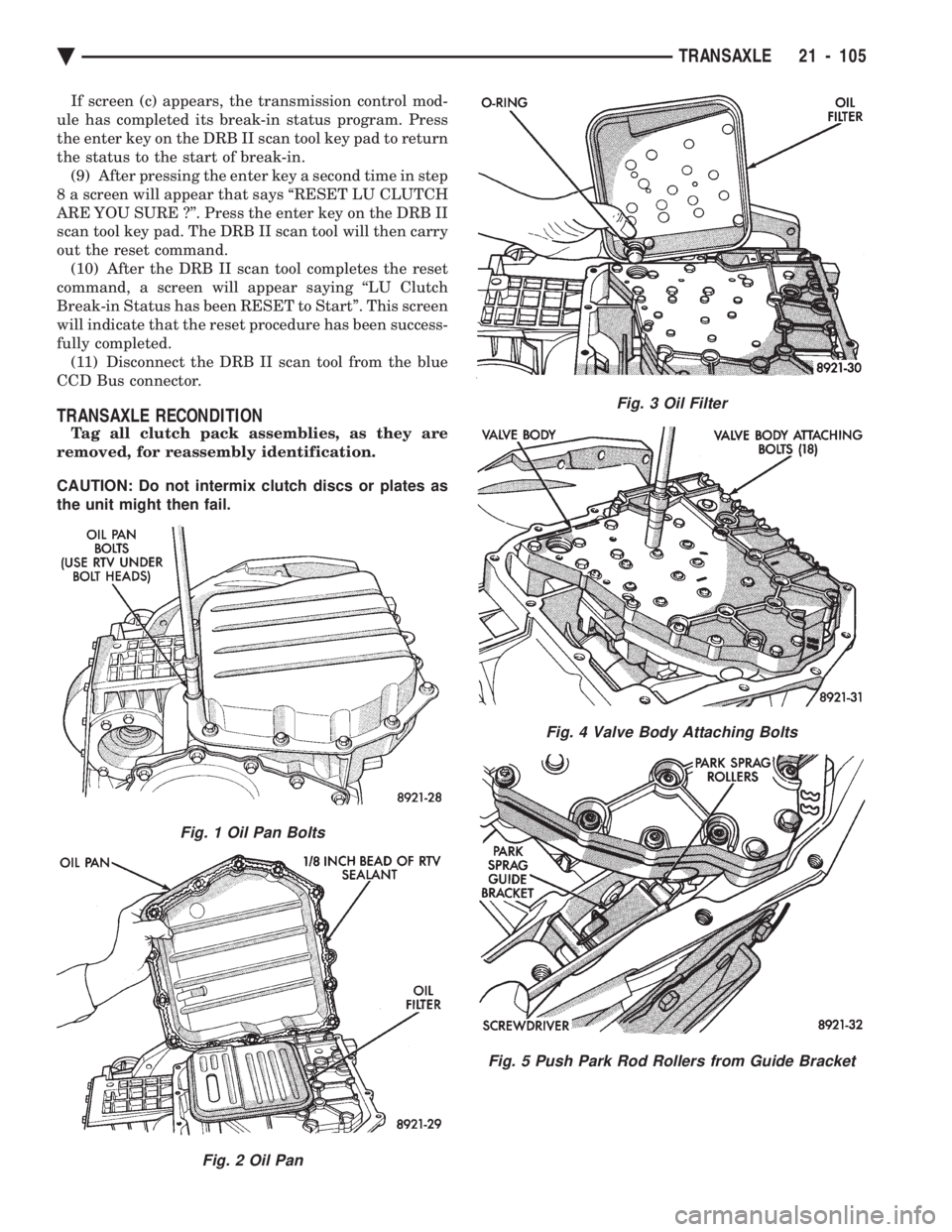
Fig. 1 Oil Pan Bolts
Fig. 2 Oil Pan
Fig. 3 Oil Filter
Fig. 4 Valve Body Attaching Bolts
Fig. 5 Push Park Rod Rollers from Guide Bracket
Ä TRANSAXLE 21 - 105
Page 2093 of 2438
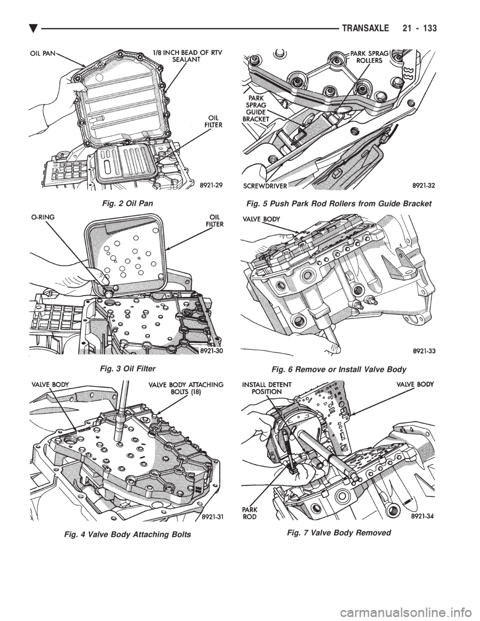
Fig. 2 Oil Pan
Fig. 3 Oil Filter
Fig. 4 Valve Body Attaching Bolts
Fig. 5 Push Park Rod Rollers from Guide Bracket
Fig. 6 Remove or Install Valve Body
Fig. 7 Valve Body Removed
Ä TRANSAXLE 21 - 133
Page 2312 of 2438
REFRIGERANT SERVICE PROCEDURES INDEX
page page
Adding Partial Refrigerant Charge ............ 10
Charging Refrigerant SystemÐEmpty System . . . 11
Discharging Refrigerant System .............. 11
Evacuating Refrigerant System .............. 11
Manifold Gauge Set Connections ............. 9 Oil Level
............................... 12
R-12 Refrigerant Equipment ................. 8
Refrigerant Recycling ...................... 9
Sight Glass Refrigerant Level Inspection ........ 8
Testing for Refrigerant Leaks ............... 10
SIGHT GLASS REFRIGERANT LEVEL INSPECTION
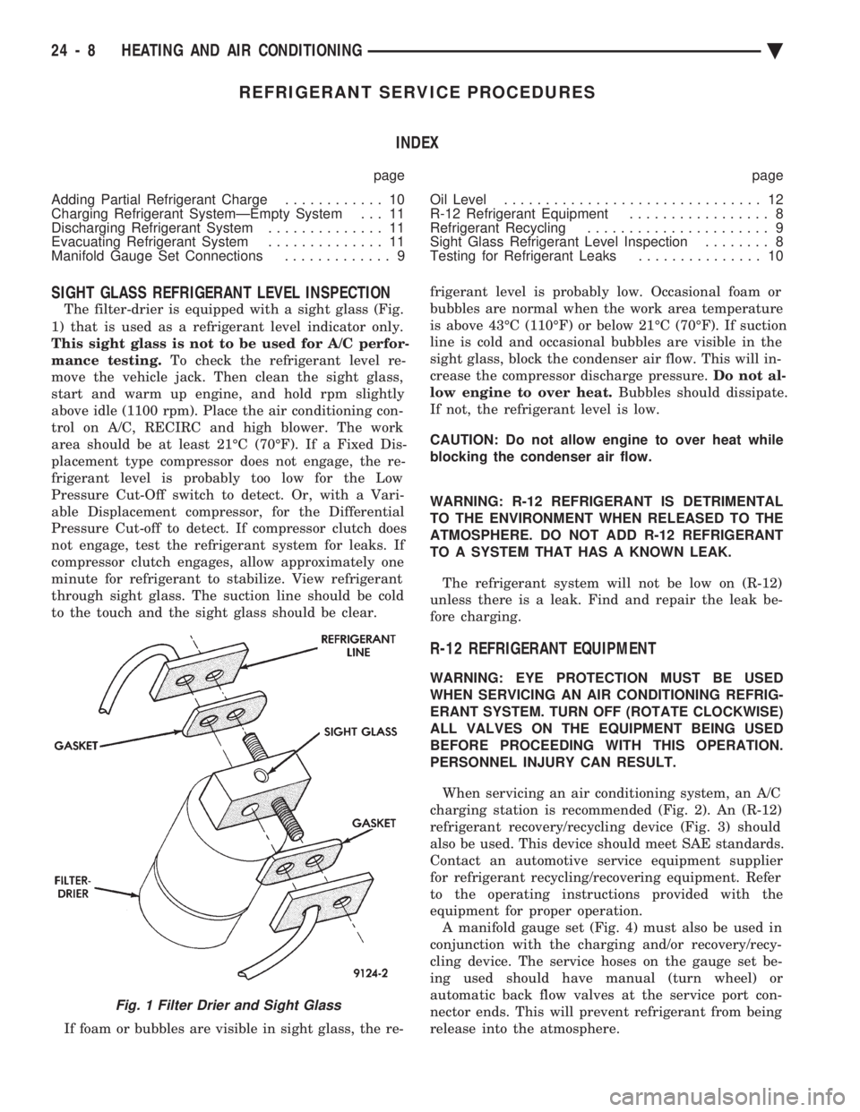
The filter-drier is equipped with a sight glass (Fig.
1) that is used as a refrigerant level indicator only.
This sight glass is not to be used for A/C perfor-
mance testing. To check the refrigerant level re-
move the vehicle jack. Then clean the sight glass,
start and warm up engine, and hold rpm slightly
above idle (1100 rpm). Place the air conditioning con-
trol on A/C, RECIRC and high blower. The work
area should be at least 21ÉC (70ÉF). If a Fixed Dis-
placement type compressor does not engage, the re-
frigerant level is probably too low for the Low
Pressure Cut-Off switch to detect. Or, with a Vari-
able Displacement compressor, for the Differential
Pressure Cut-off to detect. If compressor clutch does
not engage, test the refrigerant system for leaks. If
compressor clutch engages, allow approximately one
minute for refrigerant to stabilize. View refrigerant
through sight glass. The suction line should be cold
to the touch and the sight glass should be clear.
If foam or bubbles are visible in sight glass, the re- frigerant level is probably low. Occasional foam or
bubbles are normal when the work area temperature
is above 43ÉC (110ÉF) or below 21ÉC (70ÉF). If suction
line is cold and occasional bubbles are visible in the
sight glass, block the condenser air flow. This will in-
crease the compressor discharge pressure. Do not al-
low engine to over heat. Bubbles should dissipate.
If not, the refrigerant level is low.
CAUTION: Do not allow engine to over heat while
blocking the condenser air flow.
WARNING: R-12 REFRIGERANT IS DETRIMENTAL
TO THE ENVIRONMENT WHEN RELEASED TO THE
ATMOSPHERE. DO NOT ADD R-12 REFRIGERANT
TO A SYSTEM THAT HAS A KNOWN LEAK.
The refrigerant system will not be low on (R-12)
unless there is a leak. Find and repair the leak be-
fore charging.
R-12 REFRIGERANT EQUIPMENT
WARNING: EYE PROTECTION MUST BE USED
WHEN SERVICING AN AIR CONDITIONING REFRIG-
ERANT SYSTEM. TURN OFF (ROTATE CLOCKWISE)
ALL VALVES ON THE EQUIPMENT BEING USED
BEFORE PROCEEDING WITH THIS OPERATION.
PERSONNEL INJURY CAN RESULT.
When servicing an air conditioning system, an A/C
charging station is recommended (Fig. 2). An (R-12)
refrigerant recovery/recycling device (Fig. 3) should
also be used. This device should meet SAE standards.
Contact an automotive service equipment supplier
for refrigerant recycling/recovering equipment. Refer
to the operating instructions provided with the
equipment for proper operation. A manifold gauge set (Fig. 4) must also be used in
conjunction with the charging and/or recovery/recy-
cling device. The service hoses on the gauge set be-
ing used should have manual (turn wheel) or
automatic back flow valves at the service port con-
nector ends. This will prevent refrigerant from being
release into the atmosphere.
Fig. 1 Filter Drier and Sight Glass
24 - 8 HEATING AND AIR CONDITIONING Ä
Page 2315 of 2438
(1) Attach manifold gauge set.
(2) Open the windows of the passenger compart-
ment and set the air conditioning controls to A/C,
RECIRC, and Low blower speed. (3) Start the engine and allow it to warm up to
normal running temperature. (4) If the air conditioning compressor does not en-
gage, disconnect the low pressure cut-off switch.
Place a jumper wire across the terminals in the con-
nector boot. If the compressor still does not engage, a
problem exists in the compressor clutch feed circuit. (6) Hold the engine speed at 1400 rpm.
(7) Following the instructions provided with the
charging equipment being used. Charge through the
suction side of the system. Use enough refrigerant to
clear the sight glass in the filter drier. (8) At the point when the sight glass clears, note
the weight of the refrigerant supply drum or the
level in the charging cylinder. Then add an addi-
tional 340 g (12 oz) of refrigerant to the system. Re- move the jumper wire from the low pressure cut-off
switch connector and connect the cut-off switch.
(9) Test the over all performance of the air condi-
tioner as described in A/C Overall Performance Test
in this Group. Close all valves on the charging equip-
ment and disconnect the hoses from the service ports
as described in the Manifold Gauge Set Connections
section of this Group. Install the service port caps.
DISCHARGING REFRIGERANT SYSTEM
(R-12) refrigerant is a chlorofluorocarbon (CFC)
that can contribute to the depletion of the ozone
layer in the upper atmosphere. To help protect the
ozone layer, an R-12 refrigerant recycling device
must be used. Use this device when it is necessary to
empty the refrigerant system. Contact an automotive
service equipment supplier for refrigerant recycling
equipment. Refer to the operating instructions pro-
vided with the recycling equipment for proper opera-
tion.
EVACUATING REFRIGERANT SYSTEM
If the A/C system has been open to the atmosphere,
it must be evacuated before the system can be
charged. Moisture and air mixed with the refrigerant
will raise the compressor head pressure above accept-
able operating levels. This will reduce the perfor-
mance of the air conditioner and damage the
compressor. Moisture will boil at near room temper-
ature when exposed to vacuum. To evacuate the re-
frigerant system: (1) Connect a suitable charging station, refrigerant
recovery machine, and a manifold gauge set with
vacuum pump. (2) Open the suction and discharge valves and
start the vacuum pump. When the suction gauge
reads -88 kPa (-26 in. Hg) vacuum or greater, close
all valves and turn off vacuum pump. If the system
fails to reach specified vacuum, the refrigerant sys-
tem likely has a leak that must be corrected. If the
refrigerant system maintains specified vacuum for at
least 30 minutes, start the vacuum pump. Then open
the suction and discharge valves, and allow the sys-
tem to evacuate an additional 10 minutes. (3) Close all valves. Turn off and disconnect the
vacuum pump. The refrigerant system is prepared to be charged
with refrigerant.
CHARGING REFRIGERANT SYSTEMÐEMPTY
SYSTEM
CAUTION: Do not over charge refrigerant system,
as excessive compressor head pressure can cause
noise and system failure.
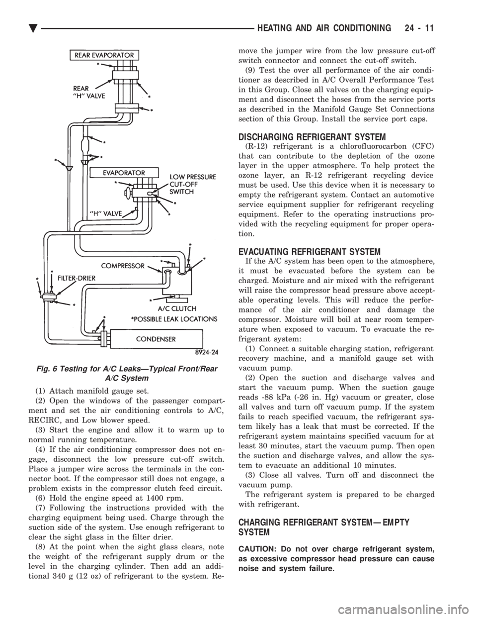
Fig. 6 Testing for A/C LeaksÐTypical Front/Rear A/C System
Ä HEATING AND AIR CONDITIONING 24 - 11