1993 CHEVROLET PLYMOUTH ACCLAIM wheel alignment
[x] Cancel search: wheel alignmentPage 147 of 2438

REAR (STUB) AXLE ALIGNMENT ALL MODELS INDEX
page page
General Information ....................... 89 Rear Wheel Alignment..................... 89
GENERAL INFORMATION
Because front wheel drive vehicles are equipped with
rear suspension incorporating stub axles (or wheel
spindles). It is possible to align both the camber and toe
of the rear wheels.
REAR WHEEL ALIGNMENT
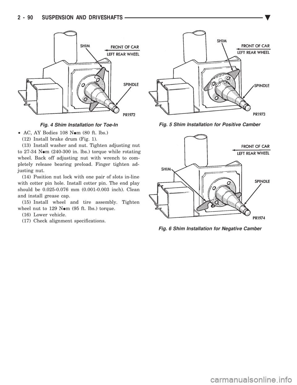
Alignment adjustment if required. Is made by adding
0.010 inch shims (from the service package kit) be-
tween the spindle mounting surface and axle mounting
plate. Each shim equals wheel change by .3É as shown
(for all car lines) in (Figs. 3 to 6). If rear wheel alignment is required, place vehicle on
alignment rack and check alignment specifications.
When recording rear toe-in (vehicle backed onto
alignment rack) REMEMBER to reverse sign
convention; a total toe-in on direct reading
charts is actually toe-out while driving. Maintain
rear alignment within Chrysler Motors recommenda-
tions, found in Specifications.
INSTALLATION OF REAR ALIGNMENT SHIMS
(1) Block front tires so vehicle will not move.
(2) Release parking brake.
(3) Hoist vehicle so that rear suspension is in full
rebound and tires are off the ground. See Hoisting in
Lubrication and Maintenance, Group 0. (4) Remove wheel and tire assembly.
(5) Pry off grease cap.
(6) Remove cotter pin and castle lock.
(7) Remove adjusting nut.
(8) Remove brake drum (Fig. 1). (9) Loosen four (4) brake assembly and spindle
mounting bolts enough to allow clearance for shim
installation (Fig. 2). Do not remove mounting
bolts.
(10) Install shims as shown in Figs. 3, 4, 5 and 6
for desired wheel change. No more than two shims
on each spindle should be used to bring alignment
within acceptable range. Wheel change by .3É per shim.
(11) Tighten down the 4 brake support plate and
spindle to axle mounting bolts until they are snug.
Then tighten the 4 bolts to the torque values listed
for the vehicle line which is being serviced.
² AA, AG, AJ, AP Bodies 75 N Im (55 ft. lbs.)
Fig. 2 Loosen Mounting Bolts
Fig. 3 Shim Installation for Toe-Out
Fig. 1 Remove Brake Drum
Ä SUSPENSION AND DRIVESHAFTS 2 - 89
Page 148 of 2438
² AC, AY Bodies 108 N Im (80 ft. lbs.)
(12) Install brake drum (Fig. 1).
(13) Install washer and nut. Tighten adjusting nut
to 27-34 N Im (240-300 in. lbs.) torque while rotating
wheel. Back off adjusting nut with wrench to com-
pletely release bearing preload. Finger tighten ad-
justing nut. (14) Position nut lock with one pair of slots in-line
with cotter pin hole. Install cotter pin. The end play
should be 0.025-0.076 mm (0.001-0.003 inch). Clean
and install grease cap. (15) Install wheel and tire assembly. Tighten
wheel nut to 129 N Im (95 ft. lbs.) torque.
(16) Lower vehicle.
(17) Check alignment specifications.
Fig. 4 Shim Installation for Toe-InFig. 5 Shim Installation for Positive Camber
Fig. 6 Shim Installation for Negative Camber
2 - 90 SUSPENSION AND DRIVESHAFTS Ä
Page 168 of 2438
REAR WHEEL DRUM BRAKES INDEX
page page
Brake Drum Refacing ..................... 21
Brake Shoe Assemblies ................... 19 Description
............................. 18
Service Procedures ....................... 18
DESCRIPTION
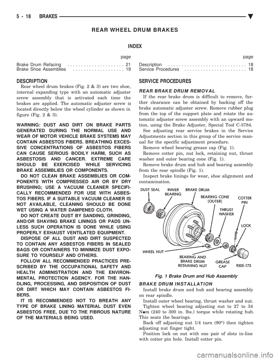
Rear wheel drum brakes (Fig .2&3)aretwoshoe,
internal expanding type with an automatic adjuster
screw assembly that is activated each time the
brakes are applied. The automatic adjuster screw is
located directly below the wheel cylinder as shown in
figure (Fig .2&3).
WARNING: DUST AND DIRT ON BRAKE PARTS
GENERATED DURING THE NORMAL USE AND
WEAR OF MOTOR VEHICLE BRAKE SYSTEMS MAY
CONTAIN ASBESTOS FIBERS. BREATHING EXCES-
SIVE CONCENTRATIONS OF ASBESTOS FIBERS
CAN CAUSE SERIOUS BODILY HARM, SUCH AS
ASBESTOSIS AND CANCER. EXTREME CARE
SHOULD BE EXERCISED WHILE SERVICING
BRAKE ASSEMBLIES OR COMPONENTS. DO NOT CLEAN BRAKE ASSEMBLIES OR COM-
PONENTS WITH COMPRESSED AIR OR BY DRY
BRUSHING; USE A VACUUM CLEANER SPECIFI-
CALLY RECOMMENDED FOR USE WITH ASBES-
TOS FIBERS. IF A SUITABLE VACUUM CLEANER IS
NOT AVAILABLE, CLEANING SHOULD BE DONE
WET USING A WATER DAMPENED CLOTH. DO NOT CREATE DUST BY SANDING, GRINDING,
AND/OR SHAVING BRAKE LININGS OR PADS UN-
LESS SUCH OPERATION IS DONE WHILE USING
PROPERLY EXHAUST VENTILATED EQUIPMENT. DISPOSE OF ALL DUST AND DIRT SUSPECTED
TO CONTAIN ANY ASBESTOS FIBERS IN SEALED
BAGS OR CONTAINERS TO MINIMIZE DUST EXPO-
SURE TO YOURSELF AND OTHERS. FOLLOW ALL RECOMMENDED PRACTICES PRE-
SCRIBED BY THE OCCUPATIONAL SAFETY AND
HEALTH ADMINISTRATION AND THE ENVIRON-
MENTAL PROTECTION AGENCY. FOR THE HAN-
DLING, PROCESSING, AND DISPOSITION OF DUST
OR DIRT WHICH MAY CONTAIN ASBESTOS FI-
BERS. IT IS RECOMMENDED NOT TO BREATH ANY
TYPE OF BRAKE LINING MATERIAL DUST EVEN
ASBESTOS FREE, DUE TO THE FIBROUS NATURE
OF THE MATERIALS BEING USED.
SERVICE PROCEDURES
REAR BRAKE DRUM REMOVAL
If the rear brake drum is difficult to remove, fur-
ther clearance can be obtained by backing off the
brake automatic adjuster screw. Remove rubber plug
from the top of the support plate and rotate the au-
tomatic adjuster screw assembly with an upward mo-
tion, using the Brake Adjuster, Special Tool C-3784. See adjusting rear service brakes in the Service
Adjustments section in this group of the service man-
ual for the specific adjustment procedure. Remove wheel bearing grease cap (Fig. 1).
Remove cotter pin, nut lock, retaining nut, thrust
washer and outer bearing cone (Fig. 1). Remove brake drum and hub and bearing assembly
from the rear spindle (Fig. 1). Inspect brake linings for wear, shoe alignment and
contamination.
BRAKE DRUM INSTALLATION
Install brake drum and hub and bearing assembly
on rear spindle. Install outer wheel bearing, thrust washer and nut.
Tighten wheel bearing adjusting nut to 27 to 34
N Im (240 to 300 in. lbs.) torque while rotating hub.
This seats the bearings. Back off adjusting nut 1/4 turn (90É) then tighten
adjusting nut finger tight. Position lock on nut with one pair of slots in-line
with cotter pin hole. Install cotter pin.
Fig. 1 Brake Drum and Hub Assembly
5 - 18 BRAKES Ä
Page 338 of 2438

(3) Clean the flywheel face with medium sandpa-
per (80-160 grade), then wipe the surface with min-
eral spirits. If the surface is severely scored, heat
checked, or warped, replace the flywheel.
CAUTION: Do not flat-machine the flywheel face.
The surface profile is tapered.
(4) The heavy side of the flywheel is indicated by a
daub of white paint near the outside diameter. To
minimize the effects of flywheel unbalance, perform
the following installation procedure: (a) Loose assemble the flywheel to the crank-
shaft. Use new flywheel attaching bolts which have
sealant on the threads. If new bolts are not avail-
able, apply Loctite sealant to the threads of the
original bolts. This sealant is required to prevent
engine oil leakage. (b) Rotate the flywheel and crankshaft until the
daub of white paint (heavy side) is at the 12 o'clock
position. (c) Torque flywheel attaching bolts to 95 N Im(70
ft. lbs.). Use a crisscross pattern when tightening
bolts.
(5) The disc assembly should be handled without
touching the facings. Replace disc if the facings show
evidence of grease or oil soakage, or wear to within
less than .38 mm (.015 inch) of the rivet heads. The
splines on the disc hub and transaxle input shaft
should be a snug fit without signs of excessive wear.
Metallic portions of disc assembly should be dry and
clean, and not been discolored from excessive heat.
Each of the arched springs between the facings
should not be broken and all rivets should be tight. (6) Wipe the friction surface of the pressure plate
with mineral spirits. (7) Using a straight edge, check clutch cover (pres-
sure plate) for flatness. The clutch cover (pressure
plate) friction area should be slightly concave, with
the inner diameter 0.02 mm to 0.1 mm (.0008 in. to
.0039 in.) below the outer diameter. It should also be
free from discoloration, burned areas, cracks,
grooves, or ridges. (8) Using a surface plate, test cover for flatness.
All sections around attaching bolt holes should be in
contact with surface plate within .015 inch. (9) The cover should be a snug fit on flywheel dow-
els. If the clutch assembly does not meet these re-
quirements, it should be replaced.
INSTALLATION
(1) Mount clutch assembly on flywheel,being care-
ful to properly align dowels and the alignment marks
made before removal. The flywheel side of the clutch
disc is marked for proper installation. If new clutch
or flywheel is installed, align cover balance spot as
close as possible to flywheel balance orange spot. Ap-
ply pressure to the alignment tool. Center the tip of the tool into the crankshaft and the sliding cone into
the clutch fingers. Tighten the clutch attaching bolts
sufficiently to hold the disc in position. (2) To avoid distortion of the clutch cover, bolts
should be tightened a few turns at a time, in a criss-
cross pattern, until they are all seated. Tighten bolts
to 28 N Im (250 in. lbs.) following a crisscross pattern
sequence. Remove clutch disc alignment tool. (3) Install transaxle. See group 21, Manual Tran-
saxle, for procedures.
RELEASE BEARING AND FORK
Remove the transaxle from the vehicle. See group
21 for removal and installation procedures.
REMOVAL AND INSTALLATION
(1) Remove clutch release shaft E-clip.
(2) Remove the clutch release shaft and then slide
the fork and bearing assembly off the bearing pilot. (3) Remove the fork from the bearing thrust plate.
(4) Examine the condition of the bearing. It is pre-
lubricated and sealed and should not be im-
mersed in oil or solvent. (5) The bearing should turn smoothly when held in
the hand under a light thrust load. A light drag
caused by the lubricant fill is normal. If the bearing
is noisy, rough, or dry, replace the complete bearing
assembly with a new bearing. (6) The bearing has a plastic sleeve pre-lubricated
at assembly. Wipe out the old grease. Refill the
sleeve cavities and coat the inner surface with mul-
tipurpose grease. If the liner is cracked or worn, re-
place the bearing assembly. (7) Check the condition of the spring clips. If the
clips are broken or distorted, replace the bearing as-
sembly. (8) Before assembling the fork, lubricate the
rounded thrust pads and the spring clip cavities with
multipurpose grease. (9) Assemble the fork to the bearing by sliding the
thrust pads under the spring clips. Be careful to
avoid distorting the spring clips. These clips prevent
the bearing thrust plate from rotating with the bear-
ing. (10) Slide the bearing and fork assembly onto the
input shaft bearing retainer. (11) Position the release shaft bushings in the
housing and install the release shaft. A small
amount of bearing grease between the release shaft
bushing and the shaft is beneficial but not required.
Install the retainer clip in the shaft groove near the
large bushing. (12) Install the release lever and retaining clip on
the outer end of the release shaft.
CLEANING PRECAUTIONS
Condensation from steam vapors tend to accumu-
late on the internal clutch mechanism when the ve-
6 - 6 MANUAL TRANSAXLE CLUTCH Ä
Page 672 of 2438

(2) Open hood and locate Power Distribution Cen-
ter forward of the left suspension tower (Fig. 3). (3) Remove cover from the center and pull the
Headlamp Close Relay (Fig. 4) to keep the headlamp
doors from closing. (4) Turn headlight switch OFF.
(5) Remove two grill mounting screws and remove
grill assembly (Fig. 5). (6) Spring tension must be relieved from the head-
lamp doors before removing headlamp motor torsion
bar clips. Locate the thumb wheel on bottom of head-
lamp motor (Fig. 6). Rotate thumb wheel approxi-
mately six to seven turns clockwise to relieve all
tension. (7) Remove torsion bar anchor clip (Fig. 7).
(8) Slide torsion bar sleeve over the torsion bar
(Fig. 8). (9) Remove three clips retaining turn signal lamp
shield to body (Fig. 9), and remove shield. (10) Remove two screws retaining headlamp cover
to headlamp cover bracket (Fig. 10). (11) Remove outer headlamp.
(12) Remove outer pivot screw (Fig. 11).
(13) Remove E-clip and door crank screw (Fig. 12).
(14) Remove three bolts retaining cam pivot to
body and remove cam pivot (Fig. 11). (15) Remove Headlamp door assembly.
INSTALLATION
Reverse the preceding operation. Before installing
torsion bar clips, the holes in the torsion bars, tor-
sion bar sleeves and headlamp door cam pivots must
be in alignment. Refer to Aligning Headlamp Doors.
HEADLAMP DRIVE MOTORÐAY BODY
REMOVAL
(1) Open headlamp doors. Refer to Headlamp Door
paragraph for instructions. (2) Remove grill mounting screws and remove grill
assembly (Fig. 5). (3) Spring tension must be relieved from headlamp
doors before removing the headlamp motor torsion
bar clips. Locate the thumb wheel on bottom of the
headlamp motor (Fig. 6). Rotate thumb wheel ap-
proximately six to seven turns (clockwise) to relieve
all tension. (4) Remove both torsion bar anchor clips (Fig. 7).
(5) Slide torsion bar sleeves over the torsion bar
(Fig. 8).
Fig. 3 Power Distribution Center
Fig. 4 Headlamp Close Relay
Fig. 5 Grill
Fig. 6 Headlamp MotorÐBottom View
8L - 30 LAMPS Ä
Page 1677 of 2438
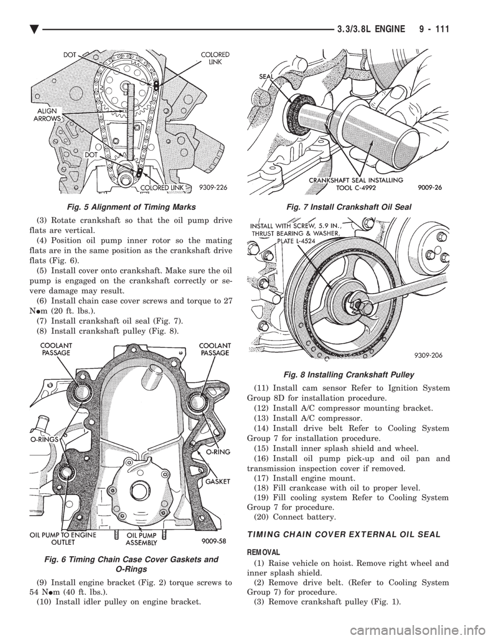
(3) Rotate crankshaft so that the oil pump drive
flats are vertical. (4) Position oil pump inner rotor so the mating
flats are in the same position as the crankshaft drive
flats (Fig. 6). (5) Install cover onto crankshaft. Make sure the oil
pump is engaged on the crankshaft correctly or se-
vere damage may result. (6) Install chain case cover screws and torque to 27
N Im (20 ft. lbs.).
(7) Install crankshaft oil seal (Fig. 7).
(8) Install crankshaft pulley (Fig. 8).
(9) Install engine bracket (Fig. 2) torque screws to
54 N Im (40 ft. lbs.).
(10) Install idler pulley on engine bracket. (11) Install cam sensor Refer to Ignition System
Group 8D for installation procedure. (12) Install A/C compressor mounting bracket.
(13) Install A/C compressor.
(14) Install drive belt Refer to Cooling System
Group 7 for installation procedure. (15) Install inner splash shield and wheel.
(16) Install oil pump pick-up and oil pan and
transmission inspection cover if removed. (17) Install engine mount.
(18) Fill crankcase with oil to proper level.
(19) Fill cooling system Refer to Cooling System
Group 7 for procedure. (20) Connect battery.
TIMING CHAIN COVER EXTERNAL OIL SEAL
REMOVAL
(1) Raise vehicle on hoist. Remove right wheel and
inner splash shield. (2) Remove drive belt. (Refer to Cooling System
Group 7) for procedure. (3) Remove crankshaft pulley (Fig. 1).
Fig. 5 Alignment of Timing Marks
Fig. 6 Timing Chain Case Cover Gaskets and O-Rings
Fig. 7 Install Crankshaft Oil Seal
Fig. 8 Installing Crankshaft Pulley
Ä 3.3/3.8L ENGINE 9 - 111
Page 1678 of 2438
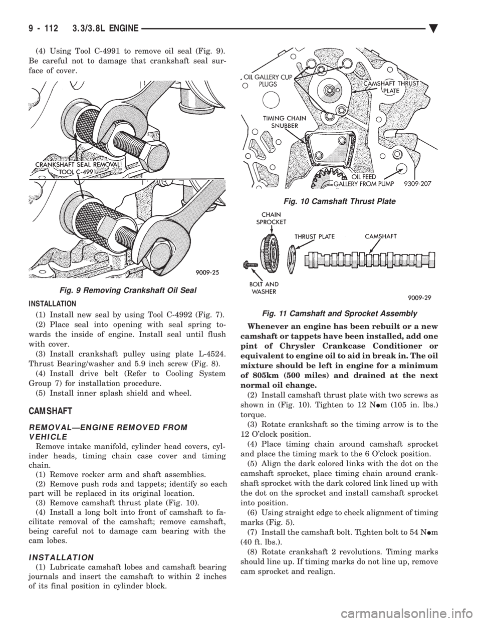
(4) Using Tool C-4991 to remove oil seal (Fig. 9).
Be careful not to damage that crankshaft seal sur-
face of cover.
INSTALLATION (1) Install new seal by using Tool C-4992 (Fig. 7).
(2) Place seal into opening with seal spring to-
wards the inside of engine. Install seal until flush
with cover. (3) Install crankshaft pulley using plate L-4524.
Thrust Bearing/washer and 5.9 inch screw (Fig. 8). (4) Install drive belt (Refer to Cooling System
Group 7) for installation procedure. (5) Install inner splash shield and wheel.
CAMSHAFT
REMOVALÐENGINE REMOVED FROM VEHICLE
Remove intake manifold, cylinder head covers, cyl-
inder heads, timing chain case cover and timing
chain. (1) Remove rocker arm and shaft assemblies.
(2) Remove push rods and tappets; identify so each
part will be replaced in its original location. (3) Remove camshaft thrust plate (Fig. 10).
(4) Install a long bolt into front of camshaft to fa-
cilitate removal of the camshaft; remove camshaft,
being careful not to damage cam bearing with the
cam lobes.
INSTALLATION
(1) Lubricate camshaft lobes and camshaft bearing
journals and insert the camshaft to within 2 inches
of its final position in cylinder block. Whenever an engine has been rebuilt or a new
camshaft or tappets have been installed, add one
pint of Chrysler Crankcase Conditioner or
equivalent to engine oil to aid in break in. The oil
mixture should be left in engine for a minimum
of 805km (500 miles) and drained at the next
normal oil change. (2) Install camshaft thrust plate with two screws as
shown in (Fig. 10). Tighten to 12 N Im (105 in. lbs.)
torque. (3) Rotate crankshaft so the timing arrow is to the
12 O'clock position. (4) Place timing chain around camshaft sprocket
and place the timing mark to the 6 O'clock position. (5) Align the dark colored links with the dot on the
camshaft sprocket, place timing chain around crank-
shaft sprocket with the dark colored link lined up with
the dot on the sprocket and install camshaft sprocket
into position. (6) Using straight edge to check alignment of timing
marks (Fig. 5). (7) Install the camshaft bolt. Tighten bolt to 54 N Im
(40 ft. lbs.). (8) Rotate crankshaft 2 revolutions. Timing marks
should line up. If timing marks do not line up, remove
cam sprocket and realign.
Fig. 9 Removing Crankshaft Oil Seal
Fig. 10 Camshaft Thrust Plate
Fig. 11 Camshaft and Sprocket Assembly
9 - 112 3.3/3.8L ENGINE Ä
Page 1945 of 2438
bolts and nut on locating stud (Fig. 2). The right rear
crossmember stud is a pilot that correctly locates
the crossmember. Tighten down this bolt first,
then torque all 4 crossmember fasteners to 122
N Im (90 ft. lbs.).
CAUTION: Proper torque on the crossmember to
frame rail mounting bolts is very important.
(3) Torque the 4 bolts (Fig. 3) attaching the steering
gear assembly to front crossmember, to 68 N Im (50 ft.
lbs.). To ensure proper alignment of the steering
gear tighten left front bolt first. (4) Attach the engine damper strut from the engine
to the crossmember (if so equipped). (5) Attach the fluid tubes (Fig. 3) from the power
steering pump to the fittings on the steering gear.
Torque the fluid pressure line to steering gear tube nut
to 31 N Im (275 in. lbs.).
(6) Mount the outer tie rod ends to the steering
knuckles. Install the tie rod end to steering knuckle
attaching nuts. Torque the tie rod end to steering
knuckle nuts to 52 N Im (38 ft. lbs.). Install cotter pin
in tie rod end. (7) Install the front tire and wheel assemblies on
vehicle. Install the wheel lug nuts and torque to 129
N Im (95 ft. lbs.).
(8) Lower vehicle.
CAUTION: Do not use automatic transmission fluid. (9) Fill power steering pump fluid reservoir to the
(Full-Cold) proper level. (10) Start the engine and let run for a few seconds.
Then turn the engine off.
(11) Add fluid if necessary.
(12) Raise front wheels of vehicle off the ground.
(13) Start engine and turn steering wheel several
times from stop to stop to bleed air from fluid in
system. Stop engine, check fluid level, and inspect
system for leaks. Fill pump reservoir to correct
level with Mopar t, Power Steering Fluid, or
equivalent. See Checking Fluid Level.
(14) Lower front wheels of vehicle back on the
ground. (15) Adjust toe (Refer to Group 2 Suspension).
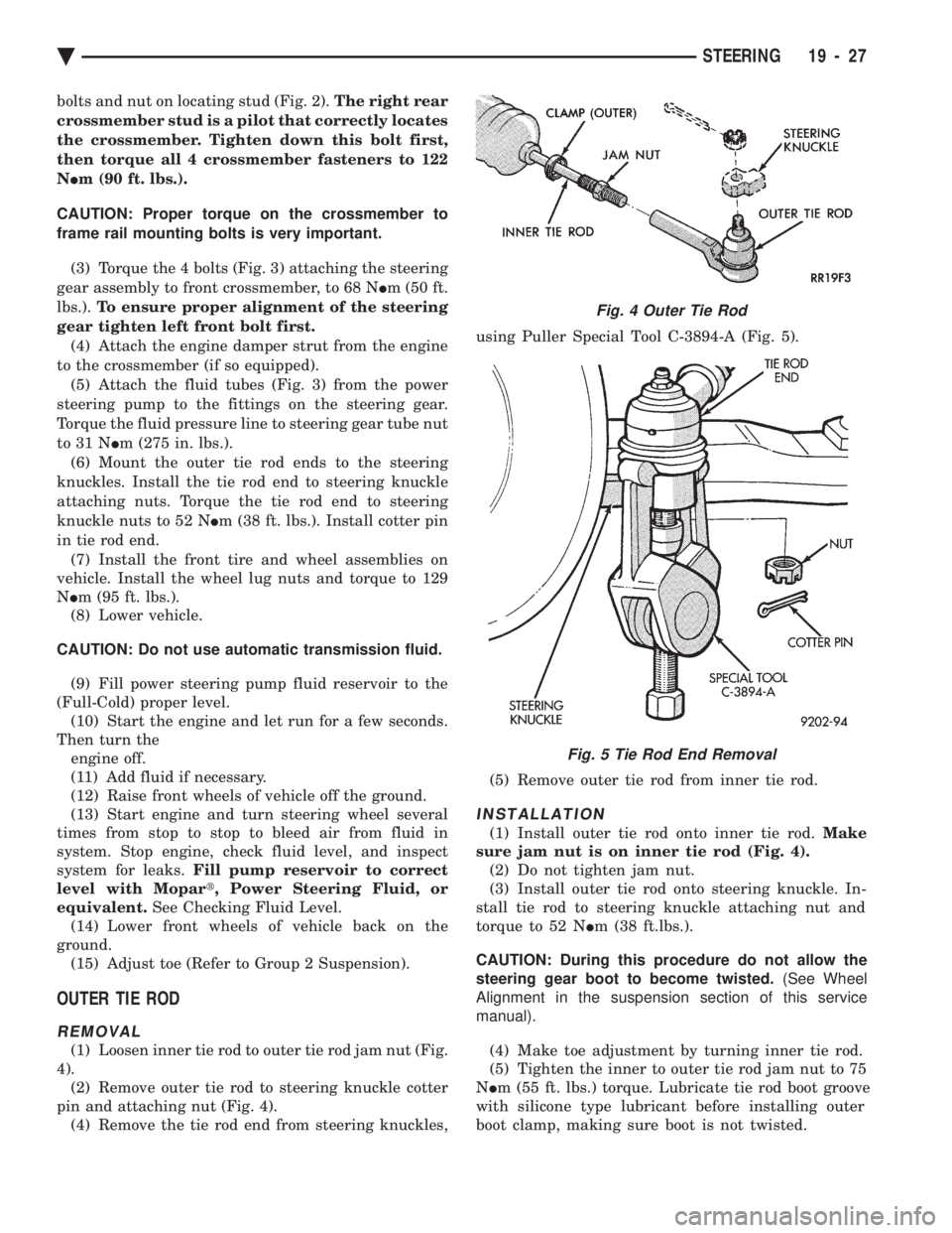
OUTER TIE ROD
REMOVAL
(1) Loosen inner tie rod to outer tie rod jam nut (Fig.
4). (2) Remove outer tie rod to steering knuckle cotter
pin and attaching nut (Fig. 4). (4) Remove the tie rod end from steering knuckles, using Puller Special Tool C-3894-A (Fig. 5).
(5) Remove outer tie rod from inner tie rod.
INSTALLATION
(1) Install outer tie rod onto inner tie rod. Make
sure jam nut is on inner tie rod (Fig. 4). (2) Do not tighten jam nut.
(3) Install outer tie rod onto steering knuckle. In-
stall tie rod to steering knuckle attaching nut and
torque to 52 N Im (38 ft.lbs.).
CAUTION: During this procedure do not allow the
steering gear boot to become twisted. (See Wheel
Alignment in the suspension section of this service
manual).
(4) Make toe adjustment by turning inner tie rod.
(5) Tighten the inner to outer tie rod jam nut to 75
N Im (55 ft. lbs.) torque. Lubricate tie rod boot groove
with silicone type lubricant before installing outer
boot clamp, making sure boot is not twisted.
Fig. 4 Outer Tie Rod
Fig. 5 Tie Rod End Removal
Ä STEERING 19 - 27