1993 CHEVROLET PLYMOUTH ACCLAIM wheel alignment
[x] Cancel search: wheel alignmentPage 31 of 2438
COMPONENT AND SYSTEM INDEX
Name Group-page Name Group-page
BODY ................................... 23-1
AA-VEHICLE BODY COMPONENT SERVICE .......23-11
AC-VEHICLE BODY COMPONENT SERVICE .......23-37
AG-VEHICLE BODY COMPONENT SERVICE .......23-52
AJ/27-VEHICLE CONVERTIBLE BODY COMPONENT SERVICE ............................ 23-86
AJ-VEHICLE BODY COMPONENT SERVICE .......23-71
AP-VEHICLE BODY COMPONENT SERVICE .......23-97
AY-VEHICLE BODY COMPONENT SERVICE .......23-133
BODY DIAGNOSTIC PROCEDURES .............23-2
GENERAL SERVICE INFORMATION .............23-1
PAINT ................................. 23-4
POWER SUNROOF ........................ 23-6
WINDSHIELD ............................ 23-9
BRAKES ..................................5-1
ANTI-LOCK BRAKE SYSTEMÐBENDIX ANTI-LOCK 10 AC/Y BODY ......................... 5-72
ANTI-LOCK BRAKE SYSTEMÐBENDIX ANTI-LOCK 6 AA,AG,AJ,AP BODY .................... 5-113
BRAKE DISC (ROTOR) ...................... 5-53
BRAKE SUPPORT ASSEMBLY .................5-25
FRONT DISC BRAKES ...................... 5-31
GENERAL INFORMATION .....................5-1
HYDRAULIC SYSTEM CONTROL VALVES .........5-26
KELSEY HAYES DOUBLE PIN FAMILY CALIPER .....5-35
KELSEY HAYES DOUBLE PIN NON-FAMILY CALIPER ............................. 5-38
MASTER CYLINDER ....................... 5-66
PARKING BRAKES ........................ 5-57
POWER BRAKES ......................... 5-68
REAR DISC BRAKES ....................... 5-45
REAR WHEEL DRUM BRAKES ................5-18
SERVICE ADJUSTMENTS .....................5-4
WHEEL BEARINGS ........................ 5-70
WHEEL CYLINDERS ....................... 5-23
COOLING SYSTEM ...........................7-1
ACCESSORY DRIVE BELTS ................... 7-24
ENGINE BLOCK HEATER .................... 7-28
GENERAL INFORMATION .....................7-1
SERVICE PROCEDURES ..................... 7-10
SPECIFICATIONS ......................... 7-29
ENGINE ..................................9-1
2.2/2.5L ENGINES .........................9-8
3.0L ENGINE ............................ 9-66
3.3/3.8L ENGINE ......................... 9-98
STANDARD SERVICE PROCEDURES .............9-1
EXHAUST SYSTEM AND INTAKE MANIFOLD .........11-1
GENERAL INFORMATION .................... 11-1
SERVICE PROCEDURES ..................... 11-4
TORQUE SPECIFICATION ................... 11-25
FRAME AND BUMPERS ....................... 13-1
BUMPER AND FASCIA ...................... 13-1
FRAME ................................ 13-9
HEATING AND AIR CONDITIONING ...............24-1
AUTOMATIC TEMPERATURE CONTROL (ATC) .....24-66 COMPONENT SERVICE PROCEDURES
..........24-47
FIXED DISPLACEMENT COMPRESSORÐMODEL 10PA17............................. 24-24
FIXED DISPLACEMENT COMPRESSORÐMODEL SD709P ............................. 24-38
FIXED DISPLACEMENT COMPRESSORÐMODEL TR105 .............................. 24-32
GENERAL INFORMATION .................... 24-1
HEATER AND A/C PERFORMANCE TESTS .........24-6
REFRIGERANT SERVICE PROCEDURES ..........24-8
VACUUM CONTROL SYSTEM DIAGNOSIS .........24-4
VARIABLE DISPLACEMENT COMPRESSORÐMODEL 6C17 ............................... 24-13
INTRODUCTION .......................... Intro.-1
LUBRICATION AND MAINTENANCE ................0-1
CHASSIS AND BODY ....................... 0-19
DRIVETRAIN ............................ 0-16
ENGINE ................................0-8
GENERAL INFORMATION .....................0-1
MANUAL TRANSAXLE CLUTCH ...................6-1
STEERING ................................ 19-1
ACUSTAR STANDARD AND TILT STEERING COLUMN ............................ 19-28
AUTOMATIC TRANSMISSION SHIFTER/IGNITION INTERLOCK .......................... 19-36
GENERAL INFORMATION .................... 19-1
POWER STEERING GEAR ................... 19-25
POWER STEERING PUMPS ..................19-1
SPECIFICATIONS AND TIGHTENING REFERENCE . . . 19-42
SUSPENSION AND DRIVESHAFTS .................2-1
AUTOMATIC AIR LOAD LEVELING SYSTEM ........2-59
AUTOMATIC AIR SUSPENSION ................2-73
DRIVESHAFTS ........................... 2-25
FRONT SUSPENSION .......................2-2
FRONT SUSPENSION SERVICE PROCEDURES .......2-5
GENERAL INFORMATION .....................2-1
REAR (STUB) AXLE ALIGNMENT ALL MODELS .....2-89
REAR SUSPENSION ....................... 2-50
SPECIFICATIONS ......................... 2-91
TRANSAXLE .............................. 21-85
41TE FOUR SPEED AUTOMATIC TRANSAXLE ......21-85
41TE FOUR SPEED TRANSAXLE HYDRAULIC SCHEMATICS ........................ 21-170
41TE ON-BOARD DIAGNOSTICS .............21-145
A-523, A-543, and A-568 MANUAL TRANSAXLE ....21-1
SPECIFICATIONS ........................ 21-183
THREE SPEED TORQUEFLITE AUTOMATIC TRANSAXLE .......................... 21-35
THREE SPEED TRANSAXLE HYDRAULIC SCHEMATICS ........................ 21-162
WHEELSÐTIRES ........................... 22-1
SPECIFICATIONS ......................... 22-8
TIRE SERVICE PROCEDURES .................22-1
WHEELS SERVICE PROCEDURES ..............22-6
Page 63 of 2438

FRONT SUSPENSION SERVICE PROCEDURES INDEX
page page
Ball Joints .............................. 13
Hub and Bearing Assembly ................. 20
Knuckle (Front Suspension) ................. 16
Lower Control Arm ....................... 10
Lower Control Arm Pivot Bushings ........... 11 Shock Absorbers (Strut Damper)
............. 10
Strut Damper Assembly ..................... 7
Suspension Coil Springs .................... 9
Sway Bar .............................. 14
Wheel Alignment .......................... 5
WHEEL ALIGNMENT
Front wheel alignment is the proper adjustment of
all interrelated front suspension angles. These angles
are what affects the running and steering of the
front wheels of the vehicle. The method of checking front alignment will vary
depending on the type of equipment being used. The
instructions furnished by the manufacturer of the
equipment should always be followed. With the ex-
ception that the alignment specifications recom-
mended by Chrysler Corporation be used. There are six basic factors which are the founda-
tion to front wheel alignment. These are height,
caster, camber, toe-in, steering axis inclination and
toe-out on turns. Of the six basic factors only camber
and toe in are mechanically adjustable (Fig. 1)
CAUTION: Do not attempt to modify any suspen-
sion or steering components by heating or bending
of the component.
Wheel alignment adjustments and checks should be
made in the following sequence. (1) Camber
(2) Toe
Camber is the number of degrees the top of the
wheel is tilted inward or outward from true vertical.
Inward tilt is negative camber. Outward tilt is posi-
tive camber. Excessive camber is a tire wear factor: negative
camber causes wear on the inside of the tire, while
positive camber causes wear to the outside. Toe
is measured in degrees or inches and is the
distance the front edges of the tires are closer (or far-
ther apart) than the rear edges. See Front Wheel
Drive Specifications for Toesettings.
PRE-ALIGNMENT
Before any attempt is made to change or correct
the wheel alignment factors. The following inspection
and necessary corrections must be made on those
parts which influence the steering of the vehicle. (1) Check and inflate tires to recommended pres-
sure. All tires should be the same size and in good
condition and have approximately the same wear.
Note type of tread wear which will aid in diagnosing,
see Wheels and Tires, Group 22. (2) Check front wheel and tire assembly for radial
runout. (3) Inspect lower ball joints and all steering link-
age for looseness. (4) Check for broken or sagged front and rear
springs. Front suspension must only be checked after the
vehicle has had the following checked or adjusted.
Tires set to recommended pressures, full tank of fuel,
no passenger or luggage compartment load and is on
a level floor or alignment rack. Just prior to each alignment reading. The vehicle
should be bounced (rear first, then front) by grasping
bumper at center and jouncing each end an equal
number of times. Always release bumpers at bottom
of down cycle.
Ä SUSPENSION AND DRIVESHAFTS 2 - 5
Page 65 of 2438
WHEEL ALIGNMENT SERVICE PROCEDURE
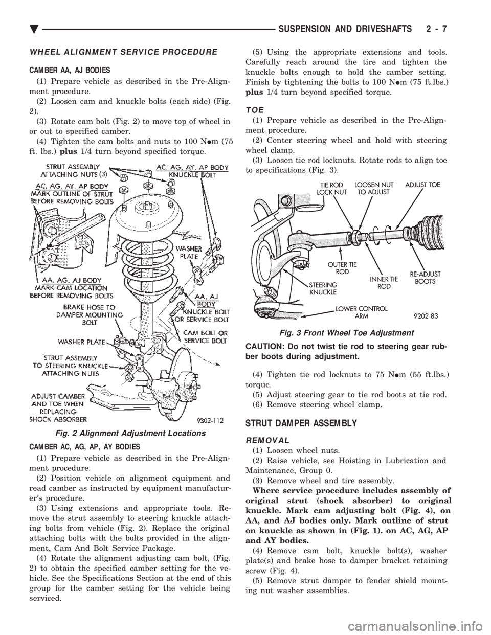
CAMBER AA, AJ BODIES (1) Prepare vehicle as described in the Pre-Align-
ment procedure. (2) Loosen cam and knuckle bolts (each side) (Fig.
2). (3) Rotate cam bolt (Fig. 2) to move top of wheel in
or out to specified camber. (4) Tighten the cam bolts and nuts to 100 N Im (75
ft. lbs.) plus1/4 turn beyond specified torque.
CAMBER AC, AG, AP, AY BODIES (1) Prepare vehicle as described in the Pre-Align-
ment procedure. (2) Position vehicle on alignment equipment and
read camber as instructed by equipment manufactur-
er's procedure. (3) Using extensions and appropriate tools. Re-
move the strut assembly to steering knuckle attach-
ing bolts from vehicle (Fig. 2). Replace the original
attaching bolts with the bolts provided in the align-
ment, Cam And Bolt Service Package. (4) Rotate the alignment adjusting cam bolt, (Fig.
2) to obtain the specified camber setting for the ve-
hicle. See the Specifications Section at the end of this
group for the camber setting for the vehicle being
serviced. (5) Using the appropriate extensions and tools.
Carefully reach around the tire and tighten the
knuckle bolts enough to hold the camber setting.
Finish by tightening the bolts to 100 N Im (75 ft.lbs.)
plus 1/4 turn beyond specified torque.
TOE
(1) Prepare vehicle as described in the Pre-Align-
ment procedure. (2) Center steering wheel and hold with steering
wheel clamp. (3) Loosen tie rod locknuts. Rotate rods to align toe
to specifications (Fig. 3).
CAUTION: Do not twist tie rod to steering gear rub-
ber boots during adjustment. (4) Tighten tie rod locknuts to 75 N Im (55 ft.lbs.)
torque. (5) Adjust steering gear to tie rod boots at tie rod.
(6) Remove steering wheel clamp.
STRUT DAMPER ASSEMBLY
REMOVAL
(1) Loosen wheel nuts.
(2) Raise vehicle, see Hoisting in Lubrication and
Maintenance, Group 0. (3) Remove wheel and tire assembly.
Where service procedure includes assembly of
original strut (shock absorber) to original
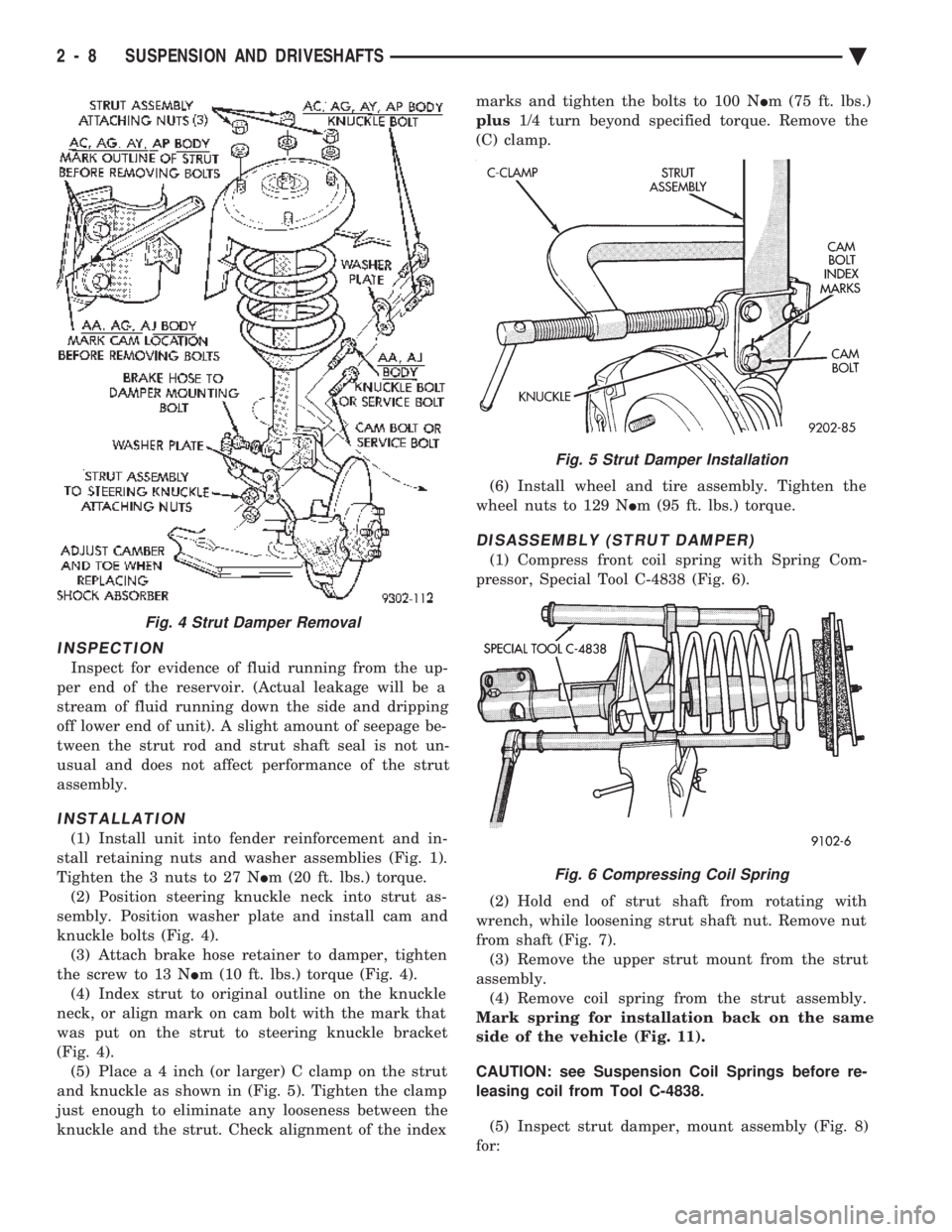
knuckle. Mark cam adjusting bolt (Fig. 4), on
AA, and AJ bodies only. Mark outline of strut
on knuckle as shown in (Fig. 1). on AC, AG, AP
and AY bodies. (4) Remove cam bolt, knuckle bolt(s), washer
plate(s) and brake hose to damper bracket retaining
screw (Fig. 4). (5) Remove strut damper to fender shield mount-
ing nut washer assemblies.
Fig. 2 Alignment Adjustment Locations
Fig. 3 Front Wheel Toe Adjustment
Ä SUSPENSION AND DRIVESHAFTS 2 - 7
Page 66 of 2438
INSPECTION
Inspect for evidence of fluid running from the up-
per end of the reservoir. (Actual leakage will be a
stream of fluid running down the side and dripping
off lower end of unit). A slight amount of seepage be-
tween the strut rod and strut shaft seal is not un-
usual and does not affect performance of the strut
assembly.
INSTALLATION
(1) Install unit into fender reinforcement and in-
stall retaining nuts and washer assemblies (Fig. 1).
Tighten the 3 nuts to 27 N Im (20 ft. lbs.) torque.
(2) Position steering knuckle neck into strut as-
sembly. Position washer plate and install cam and
knuckle bolts (Fig. 4). (3) Attach brake hose retainer to damper, tighten
the screw to 13 N Im (10 ft. lbs.) torque (Fig. 4).
(4) Index strut to original outline on the knuckle
neck, or align mark on cam bolt with the mark that
was put on the strut to steering knuckle bracket
(Fig. 4). (5) Plac e a 4 inch (or larger) C clamp on the strut
and knuckle as shown in (Fig. 5). Tighten the clamp
just enough to eliminate any looseness between the
knuckle and the strut. Check alignment of the index marks and tighten the bolts to 100 N
Im (75 ft. lbs.)
plus 1/4 turn beyond specified torque. Remove the
(C) clamp.
(6) Install wheel and tire assembly. Tighten the
wheel nuts to 129 N Im (95 ft. lbs.) torque.
DISASSEMBLY (STRUT DAMPER)
(1) Compress front coil spring with Spring Com-
pressor, Special Tool C-4838 (Fig. 6).
(2) Hold end of strut shaft from rotating with
wrench, while loosening strut shaft nut. Remove nut
from shaft (Fig. 7). (3) Remove the upper strut mount from the strut
assembly. (4) Remove coil spring from the strut assembly.
Mark spring for installation back on the same
side of the vehicle (Fig. 11).
CAUTION: see Suspension Coil Springs before re-
leasing coil from Tool C-4838.
(5) Inspect strut damper, mount assembly (Fig. 8)
for:
Fig. 4 Strut Damper Removal
Fig. 5 Strut Damper Installation
Fig. 6 Compressing Coil Spring
2 - 8 SUSPENSION AND DRIVESHAFTS Ä
Page 78 of 2438

(14) Lower vehicle.
(15) Align the front wheels of the vehicle. Use the
procedure listed under Wheel Alignment, in the
Front Suspension Service Procedures section of this
service manual.
HUB AND BEARING ASSEMBLY
The Unit III Front Hub and Bearing (Fig. 1) is used
on all Front Wheel Drive Applications. All hub and bearing assemblies mount to the steer-
ing knuckle the same way, but very by the wheel size
on the vehicle. Vehicles equipped with 14 inch wheels
have a 4 inch wheel mounting stud pattern. Vehicles
equipped with 15 inch wheels hav e a 4 1/2 inch wheel
mounting stud pattern. If a hub and bearing assembly
needs to be replaced, be sure that the replacement
assembly has the same size wheel mounting stud
pattern as the original part.
This unit is serviced only as a complete assembly
(Fig. 1). It is mounted to the steering knuckle by four
mounting bolts that are removed from the rear of the
steering knuckle (Fig. 2).
REMOVAL
Replacement of the front (drive) hub and bearing
assembly can be done without having to remove the
steering knuckle from the vehicle. (1) Remove cotter pin, hub nut lock, and spring
washer (Fig. 3). (2) Loosen hub nut while the vehicle is on the floor
with the brakes applied (Fig. 4). The hub and drive-
shaft are splined together through the knuckle
(bearing assembly) and retained by the hub nut. (3) Raise vehicle, see Hoisting Recommendations in
Group 0 of this service manual. (4) Remove the hub nut and the washer from the
stub axle (Fig. 3). (5) Remove the wheel lug nuts, and tire and wheel
assembly from the vehicle.
Fig. 16 Install Washer and Hub Nut
Fig. 17 Tighten Hub Nut
Fig. 18 Install Spring Washer, Nut Lock, & Cotter Pin
Fig. 1 Unit III Front Hub And Bearing Assembly
2 - 20 SUSPENSION AND DRIVESHAFTS Ä
Page 107 of 2438
mount have been loosened for any reason, or if vehicle
has experienced front structural damage, driveshaft
lengths must be checked and corrected, if required. A
shorter than required driveshaft length can result in ob-
jectionable noise. A longer than required driveshaft
length may result in potential damage.
Use of the following procedure will ensure satisfac-
tory driveshaft engagement under all normal vehicle
operating conditions. (1) The vehicle must be completely assembled.
Front wheels must be properly aligned and in the
straight ahead position. The vehicle must be in a po-
sition so that the full weight of the body is distrib-
uted to all four tires. A platform hoist, or front end
alignment rack, is recommended.
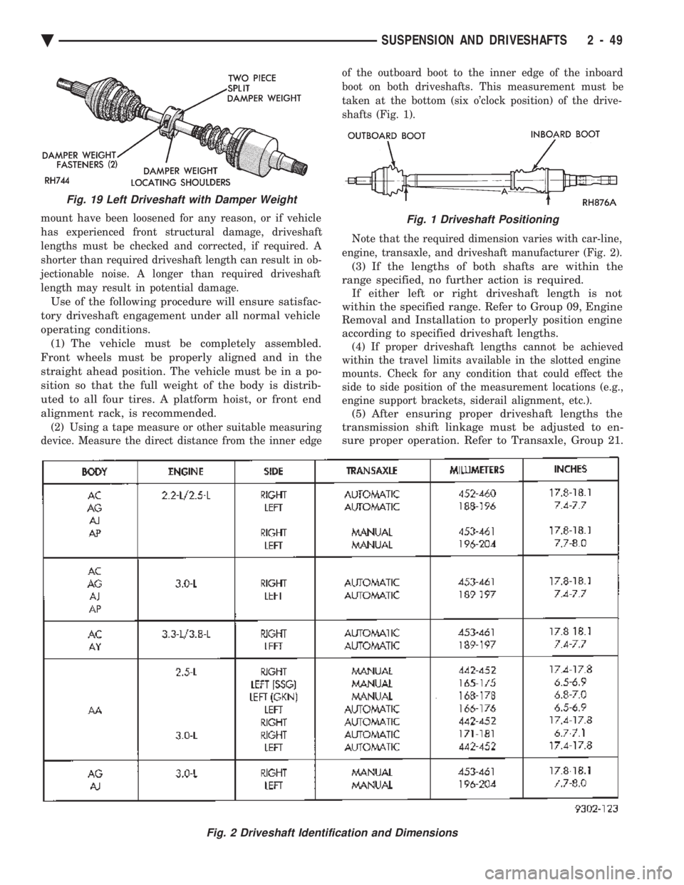
(2) Using a tape measure or other suitable measuring
device. Measure the direct distance from the inner edge of the outboard boot to the inner edge of the inboard
boot on both driveshafts. This measurement must be
taken at the bottom (six o'clock position) of the drive-
shafts (Fig. 1).
Note that the required dimension varies with car-line,
engine, transaxle, and driveshaft manufacturer (Fig. 2).
(3) If the lengths of both shafts are within the
range specified, no further action is required. If either left or right driveshaft length is not
within the specified range. Refer to Group 09, Engine
Removal and Installation to properly position engine
according to specified driveshaft lengths.
(4) If proper driveshaft lengths cannot be achieved
within the travel limits available in the slotted engine
mounts. Check for any condition that could effect the
side to side position of the measurement locations (e.g.,
engine support brackets, siderail alignment, etc.).
(5) After ensuring proper driveshaft lengths the
transmission shift linkage must be adjusted to en-
sure proper operation. Refer to Transaxle, Group 21.
Fig. 2 Driveshaft Identification and Dimensions
Fig. 19 Left Driveshaft with Damper Weight
Fig. 1 Driveshaft Positioning
Ä SUSPENSION AND DRIVESHAFTS 2 - 49
Page 109 of 2438
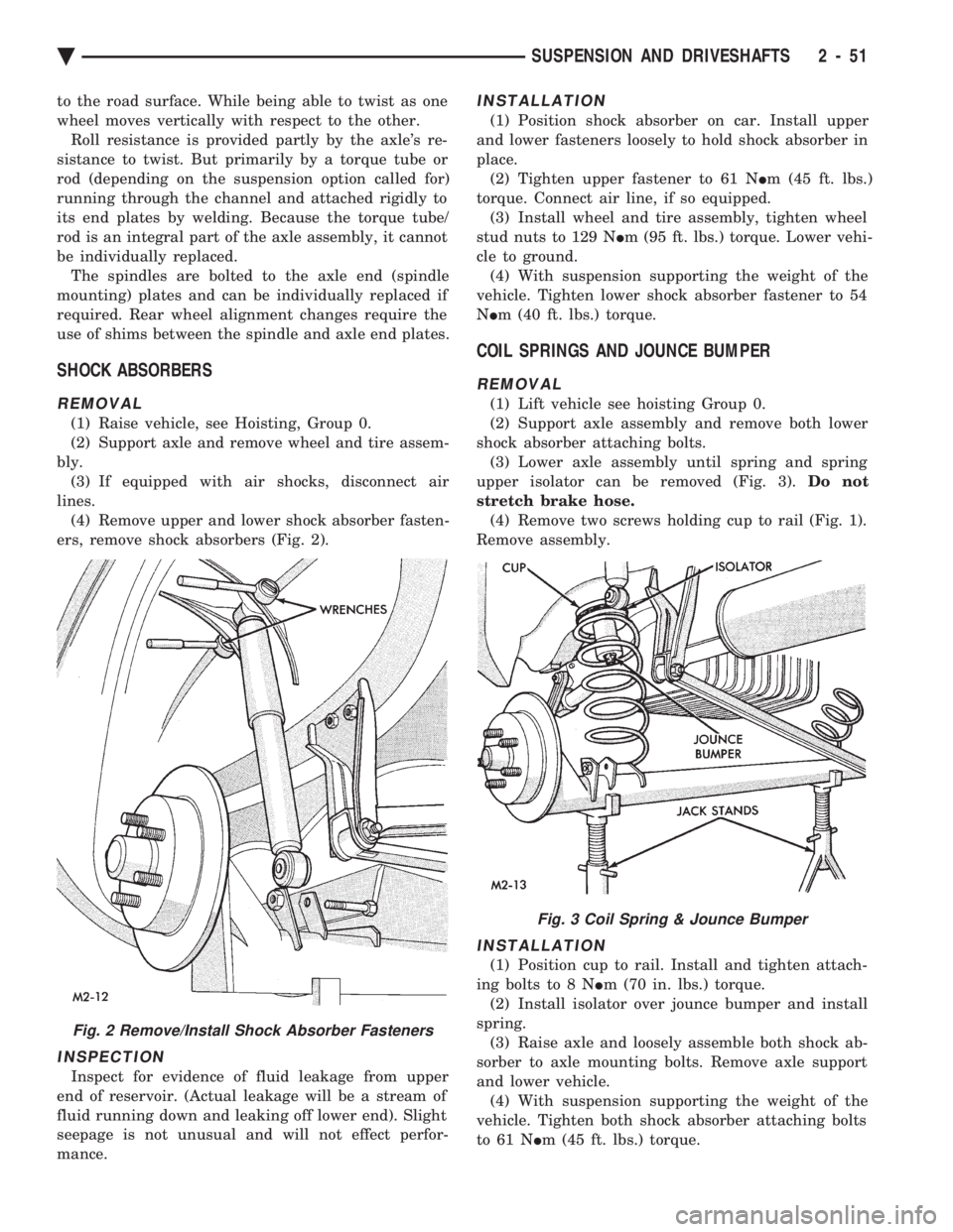
to the road surface. While being able to twist as one
wheel moves vertically with respect to the other.Roll resistance is provided partly by the axle's re-
sistance to twist. But primarily by a torque tube or
rod (depending on the suspension option called for)
running through the channel and attached rigidly to
its end plates by welding. Because the torque tube/
rod is an integral part of the axle assembly, it cannot
be individually replaced. The spindles are bolted to the axle end (spindle
mounting) plates and can be individually replaced if
required. Rear wheel alignment changes require the
use of shims between the spindle and axle end plates.
SHOCK ABSORBERS
REMOVAL
(1) Raise vehicle, see Hoisting, Group 0.
(2) Support axle and remove wheel and tire assem-
bly. (3) If equipped with air shocks, disconnect air
lines. (4) Remove upper and lower shock absorber fasten-
ers, remove shock absorbers (Fig. 2).
INSPECTION
Inspect for evidence of fluid leakage from upper
end of reservoir. (Actual leakage will be a stream of
fluid running down and leaking off lower end). Slight
seepage is not unusual and will not effect perfor-
mance.
INSTALLATION
(1) Position shock absorber on car. Install upper
and lower fasteners loosely to hold shock absorber in
place. (2) Tighten upper fastener to 61 N Im (45 ft. lbs.)
torque. Connect air line, if so equipped. (3) Install wheel and tire assembly, tighten wheel
stud nuts to 129 N Im (95 ft. lbs.) torque. Lower vehi-
cle to ground. (4) With suspension supporting the weight of the
vehicle. Tighten lower shock absorber fastener to 54
N Im (40 ft. lbs.) torque.
COIL SPRINGS AND JOUNCE BUMPER
REMOVAL
(1) Lift vehicle see hoisting Group 0.
(2) Support axle assembly and remove both lower
shock absorber attaching bolts. (3) Lower axle assembly until spring and spring
upper isolator can be removed (Fig. 3). Do not
stretch brake hose. (4) Remove two screws holding cup to rail (Fig. 1).
Remove assembly.
INSTALLATION
(1) Position cup to rail. Install and tighten attach-
ing bolts to 8 N Im (70 in. lbs.) torque.
(2) Install isolator over jounce bumper and install
spring. (3) Raise axle and loosely assemble both shock ab-
sorber to axle mounting bolts. Remove axle support
and lower vehicle. (4) With suspension supporting the weight of the
vehicle. Tighten both shock absorber attaching bolts
to 61 N Im (45 ft. lbs.) torque.
Fig. 2 Remove/Install Shock Absorber Fasteners
Fig. 3 Coil Spring & Jounce Bumper
Ä SUSPENSION AND DRIVESHAFTS 2 - 51
Page 145 of 2438

INSTALL
(1) Inspect O-Ring condition and position on sole-
noid stem. (O-Ring can become dislodged during re-
moval (Fig. 16). (2) Install solenoid with tangs to top ledge of hous-
ing and install retaining clip. (3) Reconnect air line and electrical connection.
STRUT (AIR SUSPENSION) DAMPERASSEMBLY
Service procedures for removal and installation for
(air or steel spring) assemblies are essentially the
same. Except for air venting/recharging and discon-
necting/connecting air lines and electrical connection.
REMOVAL (1) Disconnect battery negative cable.
(2) Hoist vehicle and remove wheel and tire assem-
bly. (3) See AIR LINES AND FITTINGS and discon-
nect air line. (4) Disconnect electrical leads, solenoid and height
sensors. (5) See SOLENOIDS (STRUT AND AIR SPRING)
and vent air spring and remove solenoids. (6) See STRUT DAMPER ASSEMBLY in FRONT
SUSPENSION and remove strut.
DISASSEMBLY/ASSEMBLE Disassembly is restricted to upper mount and bear-
ing housing. The strut shock absorber, air spring
with integral height sensor, solenoid and wiring har-
ness are serviced as an assembly. (1) Hold retaining plate locking washer and re-
move strut rod nut. (2) Remove locking washer, retainer plate, spacer,
flat washer and mount/bearing housing assembly
(Fig. 17). (3) Assemble in reverse order. Hold retainer plate
locking washer with suitable tool and tighten strut
rod nut to 75 N Im (55 ft. lbs.) torque.
INSTALLATION (1) See STRUT DAMPER ASSEMBLY in FRONT
SUSPENSION and install strut. (2) Install solenoid, see: SOLENOIDS (STRUT
AND AIR SPRINGS). (3) Connect electrical leads, solenoid and height
sensor. (4) Charge (inflate) air spring. See RECHARGE-
AIR SPRING to activate spring solenoid and air com-
pressor. Add air for 60 seconds.
RECHARGE AIR SPRING
To activate compressor; Ground Pin S08 to Pin
X20. To Activate Spring Solenoid:
² LF: Ground Pin S31 to X20 ²
RF: Ground Pin S30 to X20
² RR: Ground Pin S32 to X20
AIR SPRINGS REAR
REMOVAL
(1) Disconnect battery negative cable, hoist vehicle
and remove wheel and tire assembly. (2) See AIR LINES AND FITTINGS and discon-
nect air line and electrical connector from solenoid. (3) See SOLENOIDS (STRUT AND AIR SPRINGS)
and vent air from spring. Remove solenoid. (4) Release upper air spring alignment/retainer
clips. (Fig. 18) (5) Remove lower spring to axle nut (Fig. 19).
(6) Pry assembly down to pull alignment studs
through retaining clips (Fig. 20). Remove assembly.
INSTALLATION
(1) Position assembly lower stud into axle seat and
upper alignment pins through frame rail adaptor. (2) Install upper retaining clips.
(3) Install lower spring to axle nut: LOOSE AS-
SEMBLE. (4) Install solenoid and connect air line and electri-
cal connector. (5) Charge (inflate) air spring. See RECHARGING
AIR SPRING and add air for 60 seconds. (6) AFTER partial air recharge tighten lower nut
Fig. 17 Air Strut Upper Mount Assembly
Ä SUSPENSION AND DRIVESHAFTS 2 - 87