1993 CHEVROLET PLYMOUTH ACCLAIM wheel alignment
[x] Cancel search: wheel alignmentPage 1952 of 2438
(16) Connect the battery ground (negative) cable.
Test the operation of the lights and horns. If applica-
ble, reset the clock and radio.
STEERING COLUMN COMPONENT SERVICE
The Acustar tilt and standard steering columns
(Fig.1) have been designed to be serviced as an as-
sembly; less wiring, switches, shrouds, steering
wheel, etc. Also most steering column components
can be serviced without removing the steering col-
umn from the vehicle. For additional information on
electrical components refer to Group 8H Electrical.
GEAR SHIFT LEVER
The gear shift lever (if equipped) is a serviceable
component of the Acustar steering column assembly.
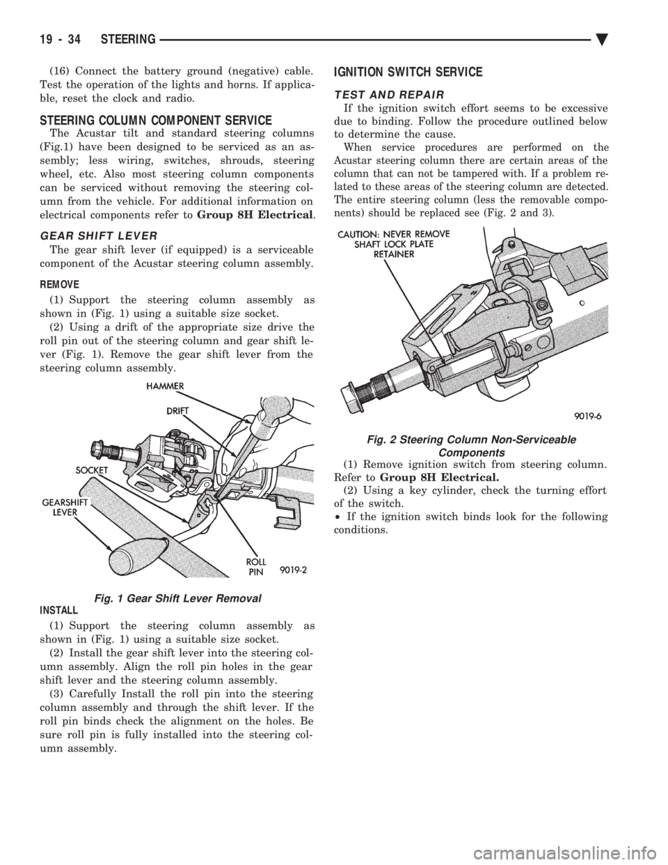
REMOVE (1) Support the steering column assembly as
shown in (Fig. 1) using a suitable size socket. (2) Using a drift of the appropriate size drive the
roll pin out of the steering column and gear shift le-
ver (Fig. 1). Remove the gear shift lever from the
steering column assembly.
INSTALL (1) Support the steering column assembly as
shown in (Fig. 1) using a suitable size socket. (2) Install the gear shift lever into the steering col-
umn assembly. Align the roll pin holes in the gear
shift lever and the steering column assembly. (3) Carefully Install the roll pin into the steering
column assembly and through the shift lever. If the
roll pin binds check the alignment on the holes. Be
sure roll pin is fully installed into the steering col-
umn assembly.
IGNITION SWITCH SERVICE
TEST AND REPAIR
If the ignition switch effort seems to be excessive
due to binding. Follow the procedure outlined below
to determine the cause.
When service procedures are performed on the
Acustar steering column there are certain areas of the
column that can not be tampered with. If a problem re-
lated to these areas of the steering column are detected.
The entire steering column (less the removable compo-
nents) should be replaced see (Fig. 2 and 3).
(1) Remove ignition switch from steering column.
Refer to Group 8H Electrical.
(2) Using a key cylinder, check the turning effort
of the switch.
² If the ignition switch binds look for the following
conditions.
Fig. 1 Gear Shift Lever Removal
Fig. 2 Steering Column Non-Serviceable Components
19 - 34 STEERING Ä
Page 2154 of 2438
WHEELS SERVICE PROCEDURES INDEX
page page
General Information ........................ 6
Tire and Wheel Balance .................... 6
Tire and Wheel Run Out .................... 7 Wheel Installation
......................... 6
Wheel Replacement ....................... 6
GENERAL INFORMATION
Original equipment wheels are designed for proper
operation at all loads up to the maximum vehicle ca-
pacity. All models use steel or cast aluminum drop center
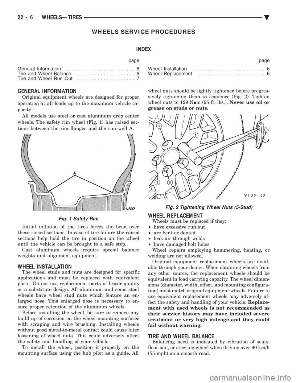
wheels. The safety rim wheel (Fig. 1) has raised sec-
tions between the rim flanges and the rim well A.
Initial inflation of the tires forces the bead over
these raised sections. In case of tire failure the raised
sections help hold the tire in position on the wheel
until the vehicle can be brought to a safe stop. Cast aluminum wheels require special balance
weights and alignment equipment.
WHEEL INSTALLATION
The wheel studs and nuts are designed for specific
applications and must be replaced with equivalent
parts. Do not use replacement parts of lessor quality
or a substitute design. All aluminum and some steel
wheels have wheel stud nuts which feature an en-
larged nose. This enlarged nose is necessary to en-
sure proper retention of the aluminum wheels. Before installing the wheel, be sure to remove any
build up of corrosion on the wheel mounting surfaces
with scraping and wire brushing. Installing wheels
without good metal-to-metal contact could cause later
loosening of wheel nuts. This could adversely affect
the safety and handling of your vehicle. To install the wheel, position it properly on the
mounting surface using the hub pilot as a guide. All wheel nuts should be lightly tightened before progres-
sively tightening them in sequence (Fig. 2). Tighten
wheel nuts to 129 N Im (95 ft. lbs.). Never use oil or
grease on studs or nuts.
WHEEL REPLACEMENT
Wheels must be replaced if they:
² have excessive run out
² are bent or dented
² leak air through welds
² have damaged bolt holes
Wheel repairs employing hammering, heating, or
welding are not allowed. Original equipment replacement wheels are avail-
able through your dealer. When obtaining wheels from
any other source, the replacement wheels should be
equivalent in load carrying capacity. The wheel dimen-
sions (diameter, width, offset, and mounting configura-
tion) must match original equipment wheels. Failure to
use equivalent replacement wheels may adversely af-
fect the safety and handling of your vehicle. Replace-
ment with used wheels is not recommended as
their service history may have included severe
treatment or very high mileage and they could
fail without warning.
TIRE AND WHEEL BALANCE
Balancing need is indicated by vibration of seats,
floor pan, or steering wheel when driving over 90 km/h
(55 mph) on a smooth road.
Fig. 1 Safety Rim
Fig. 2 Tightening Wheel Nuts (5-Stud)
22 - 6 WHEELSÐTIRES Ä
Page 2172 of 2438
(6) Separate door from vehicle.
FRONT DOOR INSTALLATION
Reverse the preceding operation. The door should
not require re-alignment. If door does need align-
ment, refer to Front Door Hinge Installation para-
graph in this section.
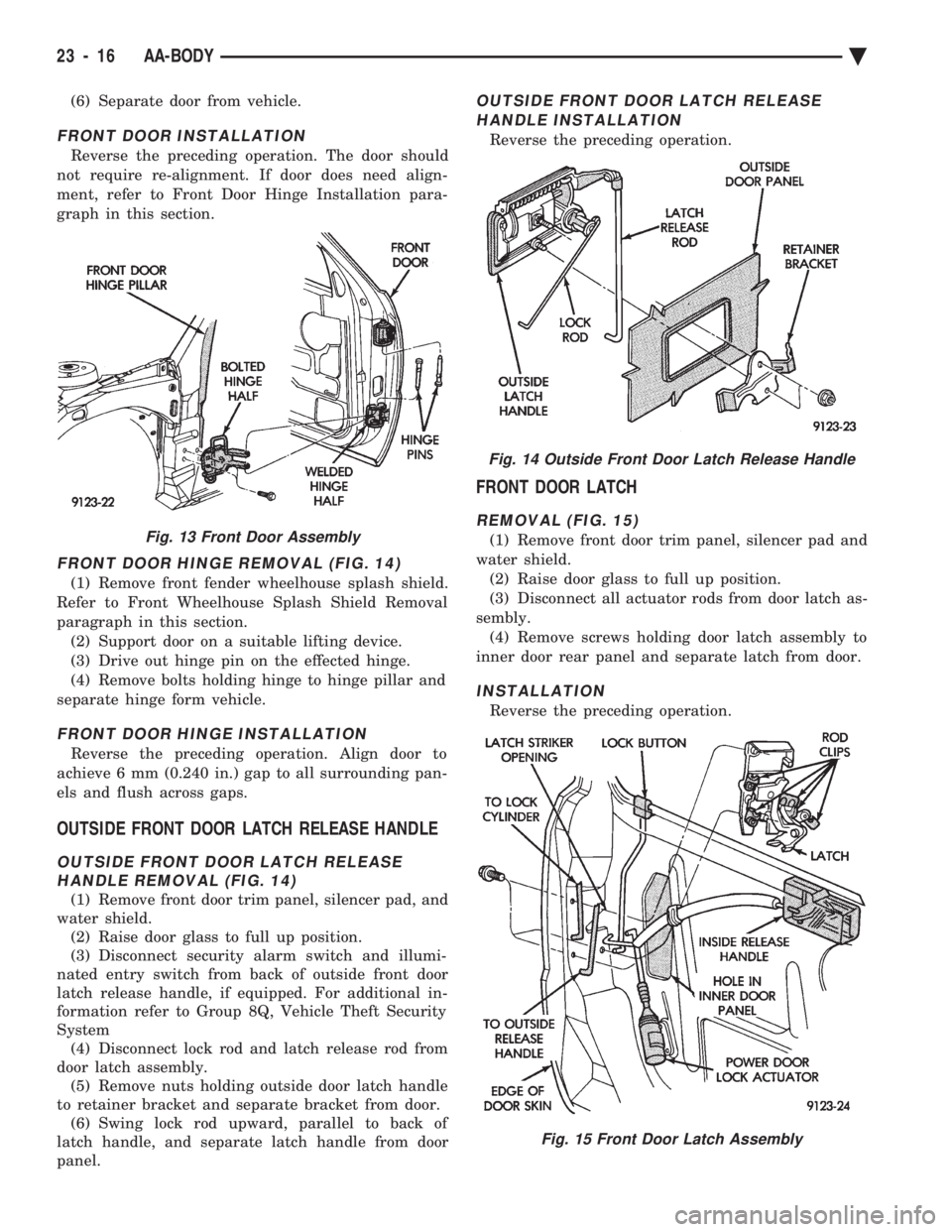
FRONT DOOR HINGE REMOVAL (FIG. 14)
(1) Remove front fender wheelhouse splash shield.
Refer to Front Wheelhouse Splash Shield Removal
paragraph in this section. (2) Support door on a suitable lifting device.
(3) Drive out hinge pin on the effected hinge.
(4) Remove bolts holding hinge to hinge pillar and
separate hinge form vehicle.
FRONT DOOR HINGE INSTALLATION
Reverse the preceding operation. Align door to
achieve 6 mm (0.240 in.) gap to all surrounding pan-
els and flush across gaps.
OUTSIDE FRONT DOOR LATCH RELEASE HANDLE
OUTSIDE FRONT DOOR LATCH RELEASE HANDLE REMOVAL (FIG. 14)
(1) Remove front door trim panel, silencer pad, and
water shield. (2) Raise door glass to full up position.
(3) Disconnect security alarm switch and illumi-
nated entry switch from back of outside front door
latch release handle, if equipped. For additional in-
formation refer to Group 8Q, Vehicle Theft Security
System (4) Disconnect lock rod and latch release rod from
door latch assembly. (5) Remove nuts holding outside door latch handle
to retainer bracket and separate bracket from door. (6) Swing lock rod upward, parallel to back of
latch handle, and separate latch handle from door
panel.
OUTSIDE FRONT DOOR LATCH RELEASE
HANDLE INSTALLATION
Reverse the preceding operation.
FRONT DOOR LATCH
REMOVAL (FIG. 15)
(1) Remove front door trim panel, silencer pad and
water shield. (2) Raise door glass to full up position.
(3) Disconnect all actuator rods from door latch as-
sembly. (4) Remove screws holding door latch assembly to
inner door rear panel and separate latch from door.
INSTALLATION
Reverse the preceding operation.
Fig. 13 Front Door Assembly
Fig. 14 Outside Front Door Latch Release Handle
Fig. 15 Front Door Latch Assembly
23 - 16 AA-BODY Ä
Page 2197 of 2438
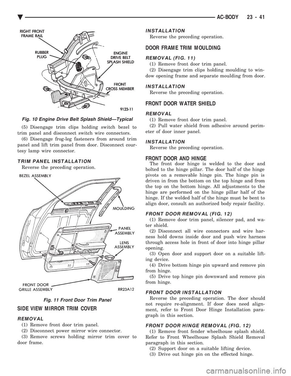
(5) Disengage trim clips holding switch bezel to
trim panel and disconnect switch wire connectors. (6) Disengage frog-leg fasteners from around trim
panel and lift trim panel from door. Disconnect cour-
tesy lamp wire connector.
TRIM PANEL INSTALLATION
Reverse the preceding operation.
SIDE VIEW MIRROR TRIM COVER
REMOVAL
(1) Remove front door trim panel.
(2) Disconnect power mirror wire connector.
(3) Remove screws holding mirror trim cover to
door frame.
INSTALLATION
Reverse the preceding operation.
DOOR FRAME TRIM MOULDING
REMOVAL (FIG. 11)
(1) Remove front door trim panel.
(2) Disengage trim clips holding moulding to win-
dow opening frame and separate moulding from door.
INSTALLATION
Reverse the preceding operation.
FRONT DOOR WATER SHIELD
REMOVAL
(1) Remove front door trim panel.
(2) Pull water shield from adhesive around perim-
eter of door inner panel.
INSTALLATION
Reverse the preceding operation.
FRONT DOOR AND HINGE
The front door hinge is welded to the door and
bolted to the hinge pillar. The door half of the hinge
pivots on a removable hinge pin. The hinge pin is
driven in from the bottom on the top hinge and from
the top on the bottom hinge. All adjustments to the
hinge are performed on the hinge pillar half of the
hinge. If the welded half of the hinge must be bent to
align door, consult an authorized body repair facility.
FRONT DOOR REMOVAL (FIG. 12)
(1) Remove door trim panel, silencer pad, and wa-
ter shield. (2) Disconnect all wire connectors and wire har-
ness hold downs inside door and push wire harness
through access hole in front of door into hinge pillar
opening. (3) Open door and support door on a suitable lift-
ing device. (4) Drive bottom hinge pin upward and remove pin
from hinge. (5) Drive top hinge pin downward and remove pin
from hinge.
FRONT DOOR INSTALLATION
Reverse the preceding operation. The door should
not require re-alignment. If door does need align-
ment, refer to Front Door Hinge Installation para-
graph in this section.
FRONT DOOR HINGE REMOVAL (FIG. 12)
(1) Remove front fender wheelhouse splash shield.
Refer to Front Wheelhouse Splash Shield Removal
paragraph in this section. (2) Support door on a suitable lifting device.
(3) Drive out hinge pin on the effected hinge.
Fig. 10 Engine Drive Belt Splash ShieldÐTypical
Fig. 11 Front Door Trim Panel
Ä AC-BODY 23 - 41
Page 2210 of 2438
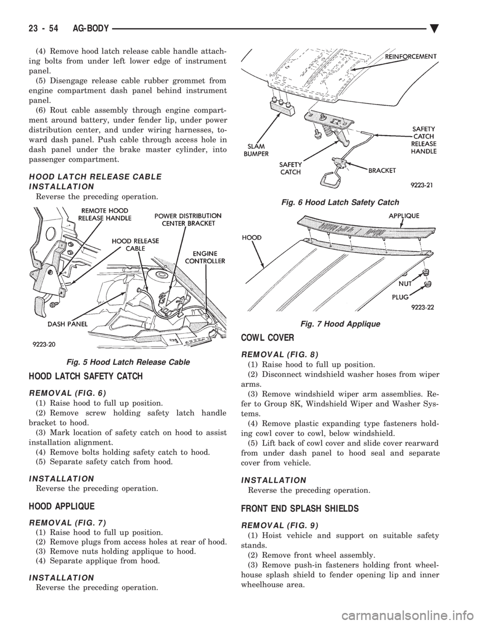
(4) Remove hood latch release cable handle attach-
ing bolts from under left lower edge of instrument
panel. (5) Disengage release cable rubber grommet from
engine compartment dash panel behind instrument
panel. (6) Rout cable assembly through engine compart-
ment around battery, under fender lip, under power
distribution center, and under wiring harnesses, to-
ward dash panel. Push cable through access hole in
dash panel under the brake master cylinder, into
passenger compartment.
HOOD LATCH RELEASE CABLE INSTALLATION
Reverse the preceding operation.
HOOD LATCH SAFETY CATCH
REMOVAL (FIG. 6)
(1) Raise hood to full up position.
(2) Remove screw holding safety latch handle
bracket to hood. (3) Mark location of safety catch on hood to assist
installation alignment. (4) Remove bolts holding safety catch to hood.
(5) Separate safety catch from hood.
INSTALLATION
Reverse the preceding operation.
HOOD APPLIQUE
REMOVAL (FIG. 7)
(1) Raise hood to full up position.
(2) Remove plugs from access holes at rear of hood.
(3) Remove nuts holding applique to hood.
(4) Separate applique from hood.
INSTALLATION
Reverse the preceding operation.
COWL COVER
REMOVAL (FIG. 8)
(1) Raise hood to full up position.
(2) Disconnect windshield washer hoses from wiper
arms. (3) Remove windshield wiper arm assemblies. Re-
fer to Group 8K, Windshield Wiper and Washer Sys-
tems. (4) Remove plastic expanding type fasteners hold-
ing cowl cover to cowl, below windshield. (5) Lift back of cowl cover and slide cover rearward
from under dash panel to hood seal and separate
cover from vehicle.
INSTALLATION
Reverse the preceding operation.
FRONT END SPLASH SHIELDS
REMOVAL (FIG. 9)
(1) Hoist vehicle and support on suitable safety
stands. (2) Remove front wheel assembly.
(3) Remove push-in fasteners holding front wheel-
house splash shield to fender opening lip and inner
wheelhouse area.
Fig. 5 Hood Latch Release Cable
Fig. 6 Hood Latch Safety Catch
Fig. 7 Hood Applique
23 - 54 AG-BODY Ä
Page 2213 of 2438
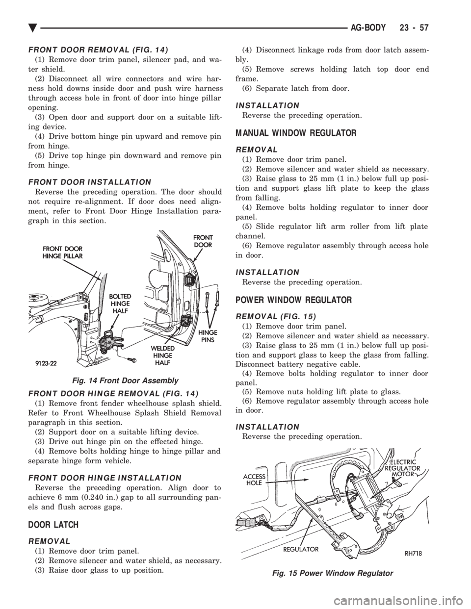
FRONT DOOR REMOVAL (FIG. 14)
(1) Remove door trim panel, silencer pad, and wa-
ter shield. (2) Disconnect all wire connectors and wire har-
ness hold downs inside door and push wire harness
through access hole in front of door into hinge pillar
opening. (3) Open door and support door on a suitable lift-
ing device. (4) Drive bottom hinge pin upward and remove pin
from hinge. (5) Drive top hinge pin downward and remove pin
from hinge.
FRONT DOOR INSTALLATION
Reverse the preceding operation. The door should
not require re-alignment. If door does need align-
ment, refer to Front Door Hinge Installation para-
graph in this section.
FRONT DOOR HINGE REMOVAL (FIG. 14)
(1) Remove front fender wheelhouse splash shield.
Refer to Front Wheelhouse Splash Shield Removal
paragraph in this section. (2) Support door on a suitable lifting device.
(3) Drive out hinge pin on the effected hinge.
(4) Remove bolts holding hinge to hinge pillar and
separate hinge form vehicle.
FRONT DOOR HINGE INSTALLATION
Reverse the preceding operation. Align door to
achieve 6 mm (0.240 in.) gap to all surrounding pan-
els and flush across gaps.
DOOR LATCH
REMOVAL
(1) Remove door trim panel.
(2) Remove silencer and water shield, as necessary.
(3) Raise door glass to up position. (4) Disconnect linkage rods from door latch assem-
bly. (5) Remove screws holding latch top door end
frame. (6) Separate latch from door.
INSTALLATION
Reverse the preceding operation.
MANUAL WINDOW REGULATOR
REMOVAL
(1) Remove door trim panel.
(2) Remove silencer and water shield as necessary.
(3) Raise glass to 25 mm (1 in.) below full up posi-
tion and support glass lift plate to keep the glass
from falling. (4) Remove bolts holding regulator to inner door
panel. (5) Slide regulator lift arm roller from lift plate
channel. (6) Remove regulator assembly through access hole
in door.
INSTALLATION
Reverse the preceding operation.
POWER WINDOW REGULATOR
REMOVAL (FIG. 15)
(1) Remove door trim panel.
(2) Remove silencer and water shield as necessary.
(3) Raise glass to 25 mm (1 in.) below full up posi-
tion and support glass to keep the glass from falling.
Disconnect battery negative cable. (4) Remove bolts holding regulator to inner door
panel. (5) Remove nuts holding lift plate to glass.
(6) Remove regulator assembly through access hole
in door.
INSTALLATION
Reverse the preceding operation.
Fig. 14 Front Door Assembly
Fig. 15 Power Window Regulator
Ä AG-BODY 23 - 57
Page 2231 of 2438
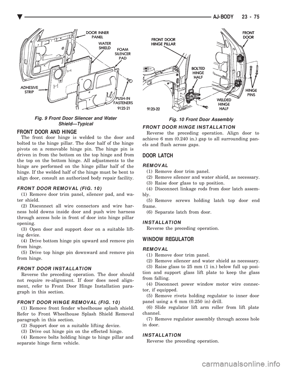
FRONT DOOR AND HINGE
The front door hinge is welded to the door and
bolted to the hinge pillar. The door half of the hinge
pivots on a removable hinge pin. The hinge pin is
driven in from the bottom on the top hinge and from
the top on the bottom hinge. All adjustments to the
hinge are performed on the hinge pillar half of the
hinge. If the welded half of the hinge must be bent to
align door, consult an authorized body repair facility.
FRONT DOOR REMOVAL (FIG. 10)
(1) Remove door trim panel, silencer pad, and wa-
ter shield. (2) Disconnect all wire connectors and wire har-
ness hold downs inside door and push wire harness
through access hole in front of door into hinge pillar
opening. (3) Open door and support door on a suitable lift-
ing device. (4) Drive bottom hinge pin upward and remove pin
from hinge. (5) Drive top hinge pin downward and remove pin
from hinge.
FRONT DOOR INSTALLATION
Reverse the preceding operation. The door should
not require re-alignment. If door does need align-
ment, refer to Front Door Hinge Installation para-
graph in this section.
FRONT DOOR HINGE REMOVAL (FIG. 10)
(1) Remove front fender wheelhouse splash shield.
Refer to Front Wheelhouse Splash Shield Removal
paragraph in this section. (2) Support door on a suitable lifting device.
(3) Drive out hinge pin on the effected hinge.
(4) Remove bolts holding hinge to hinge pillar and
separate hinge form vehicle.
FRONT DOOR HINGE INSTALLATION
Reverse the preceding operation. Align door to
achieve 6 mm (0.240 in.) gap to all surrounding pan-
els and flush across gaps.
DOOR LATCH
REMOVAL
(1) Remove door trim panel.
(2) Remove silencer and water shield, as necessary.
(3) Raise door glass to up position.
(4) Disconnect linkage rods from door latch assem-
bly. (5) Remove screws holding latch top door end
frame. (6) Separate latch from door.
INSTALLATION
Reverse the preceding operation.
WINDOW REGULATOR
REMOVAL
(1) Remove door trim panel.
(2) Remove silencer and water shield as necessary.
(3) Raise glass to 25 mm (1 in.) below full up posi-
tion and support glass lift plate to keep the glass
from falling. (4) Disconnect power window motor wire connec-
tor, if equipped. (5) Remove rivets holding regulator to inner door
panel usin ga6mm (0.250 in) drill.
(6) Slide regulator lift arm roller from lift plate
channel. (7) Remove regulator assembly through access hole
in door.
INSTALLATION
Reverse the preceding operation.
Fig. 9 Front Door Silencer and Water ShieldÐTypicalFig. 10 Front Door Assembly
Ä AJ-BODY 23 - 75
Page 2256 of 2438
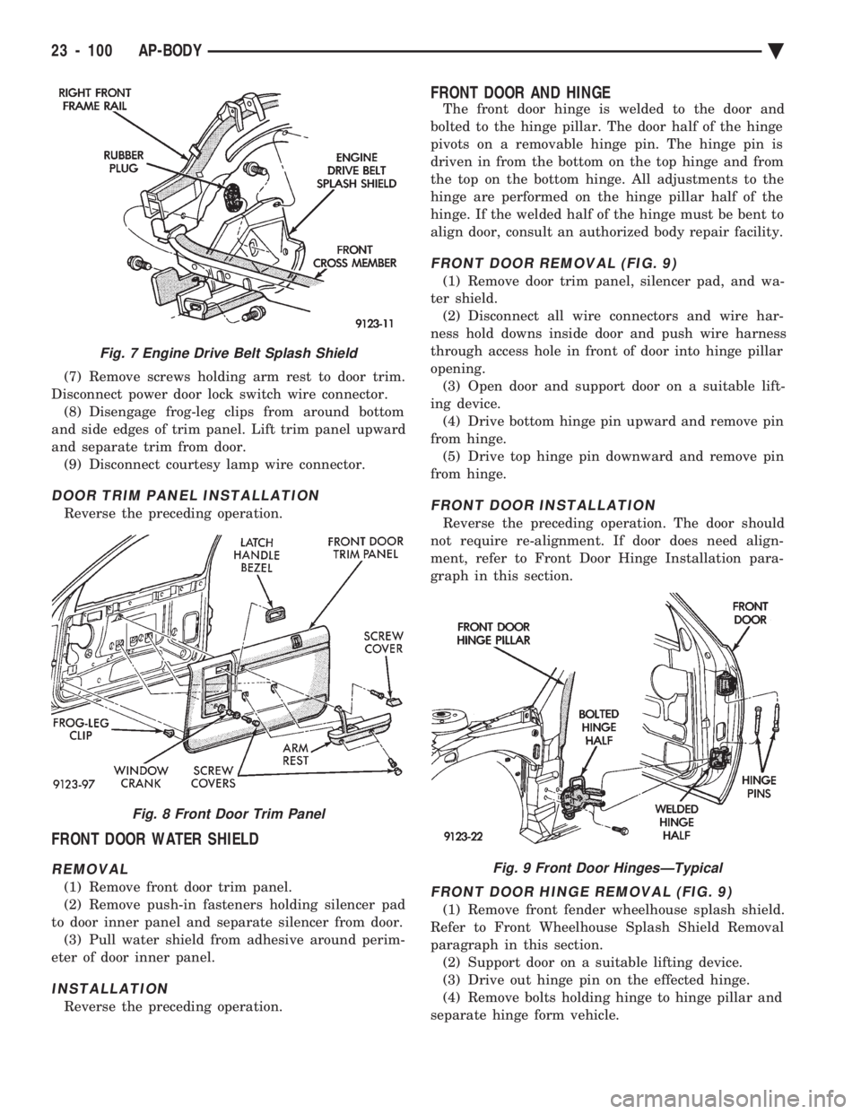
(7) Remove screws holding arm rest to door trim.
Disconnect power door lock switch wire connector. (8) Disengage frog-leg clips from around bottom
and side edges of trim panel. Lift trim panel upward
and separate trim from door. (9) Disconnect courtesy lamp wire connector.
DOOR TRIM PANEL INSTALLATION
Reverse the preceding operation.
FRONT DOOR WATER SHIELD
REMOVAL
(1) Remove front door trim panel.
(2) Remove push-in fasteners holding silencer pad
to door inner panel and separate silencer from door. (3) Pull water shield from adhesive around perim-
eter of door inner panel.
INSTALLATION
Reverse the preceding operation.
FRONT DOOR AND HINGE
The front door hinge is welded to the door and
bolted to the hinge pillar. The door half of the hinge
pivots on a removable hinge pin. The hinge pin is
driven in from the bottom on the top hinge and from
the top on the bottom hinge. All adjustments to the
hinge are performed on the hinge pillar half of the
hinge. If the welded half of the hinge must be bent to
align door, consult an authorized body repair facility.
FRONT DOOR REMOVAL (FIG. 9)
(1) Remove door trim panel, silencer pad, and wa-
ter shield. (2) Disconnect all wire connectors and wire har-
ness hold downs inside door and push wire harness
through access hole in front of door into hinge pillar
opening. (3) Open door and support door on a suitable lift-
ing device. (4) Drive bottom hinge pin upward and remove pin
from hinge. (5) Drive top hinge pin downward and remove pin
from hinge.
FRONT DOOR INSTALLATION
Reverse the preceding operation. The door should
not require re-alignment. If door does need align-
ment, refer to Front Door Hinge Installation para-
graph in this section.
FRONT DOOR HINGE REMOVAL (FIG. 9)
(1) Remove front fender wheelhouse splash shield.
Refer to Front Wheelhouse Splash Shield Removal
paragraph in this section. (2) Support door on a suitable lifting device.
(3) Drive out hinge pin on the effected hinge.
(4) Remove bolts holding hinge to hinge pillar and
separate hinge form vehicle.
Fig. 7 Engine Drive Belt Splash Shield
Fig. 8 Front Door Trim Panel
Fig. 9 Front Door HingesÐTypical
23 - 100 AP-BODY Ä