1993 CHEVROLET DYNASTY service
[x] Cancel search: servicePage 1618 of 2438
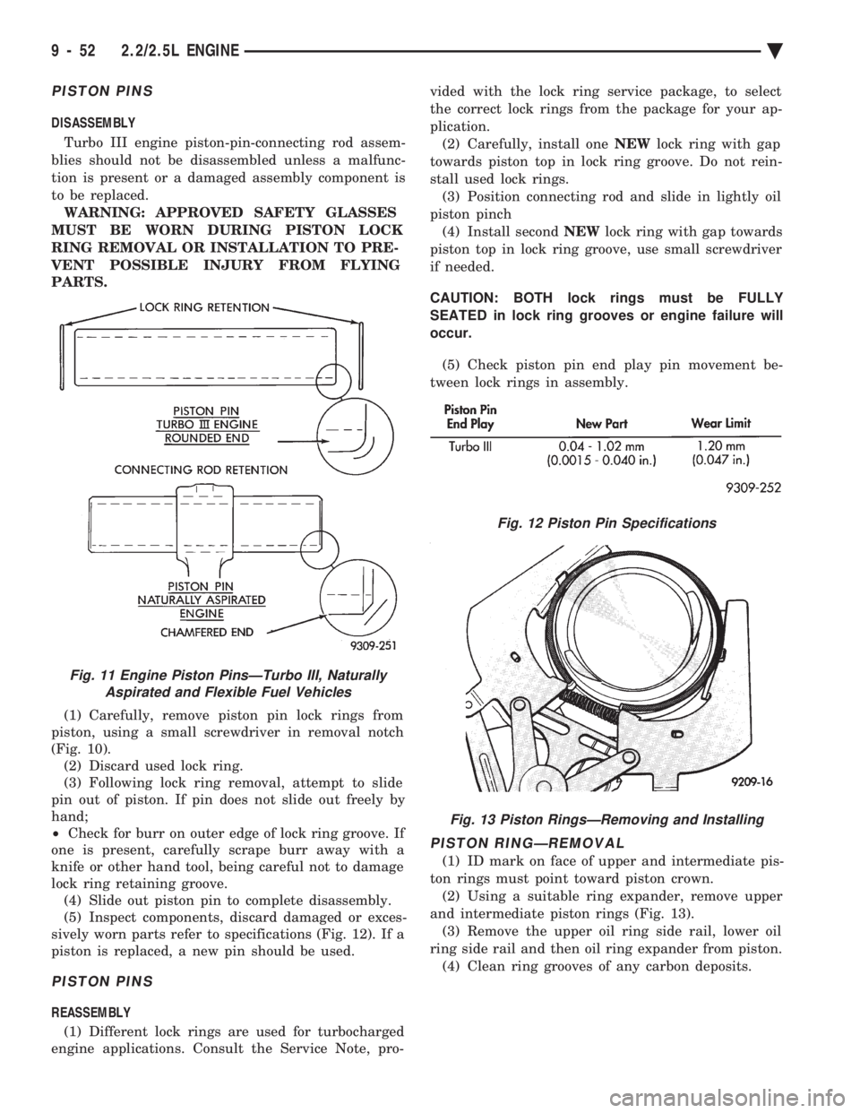
PISTON PINS
DISASSEMBLY Turbo III engine piston-pin-connecting rod assem-
blies should not be disassembled unless a malfunc-
tion is present or a damaged assembly component is
to be replaced. WARNING: APPROVED SAFETY GLASSES
MUST BE WORN DURING PISTON LOCK
RING REMOVAL OR INSTALLATION TO PRE-
VENT POSSIBLE INJURY FROM FLYING
PARTS.
(1) Carefully, remove piston pin lock rings from
piston, using a small screwdriver in removal notch
(Fig. 10). (2) Discard used lock ring.
(3) Following lock ring removal, attempt to slide
pin out of piston. If pin does not slide out freely by
hand;
² Check for burr on outer edge of lock ring groove. If
one is present, carefully scrape burr away with a
knife or other hand tool, being careful not to damage
lock ring retaining groove. (4) Slide out piston pin to complete disassembly.
(5) Inspect components, discard damaged or exces-
sively worn parts refer to specifications (Fig. 12). If a
piston is replaced, a new pin should be used.
PISTON PINS
REASSEMBLY
(1) Different lock rings are used for turbocharged
engine applications. Consult the Service Note, pro- vided with the lock ring service package, to select
the correct lock rings from the package for your ap-
plication.
(2) Carefully, install one NEWlock ring with gap
towards piston top in lock ring groove. Do not rein-
stall used lock rings. (3) Position connecting rod and slide in lightly oil
piston pinch (4) Install second NEWlock ring with gap towards
piston top in lock ring groove, use small screwdriver
if needed.
CAUTION: BOTH lock rings must be FULLY
SEATED in lock ring grooves or engine failure will
occur.
(5) Check piston pin end play pin movement be-
tween lock rings in assembly.
PISTON RINGÐREMOVAL
(1) ID mark on face of upper and intermediate pis-
ton rings must point toward piston crown. (2) Using a suitable ring expander, remove upper
and intermediate piston rings (Fig. 13). (3) Remove the upper oil ring side rail, lower oil
ring side rail and then oil ring expander from piston. (4) Clean ring grooves of any carbon deposits.
Fig. 11 Engine Piston PinsÐTurbo III, Naturally Aspirated and Flexible Fuel Vehicles
Fig. 12 Piston Pin Specifications
Fig. 13 Piston RingsÐRemoving and Installing
9 - 52 2.2/2.5L ENGINE Ä
Page 1621 of 2438
CONNECTING RODS
(1) Follow procedure specified in the Standard Ser-
vice Procedures Section for Measuring Main Bearing
Clearance and Connecting Rod Bearing Clearance
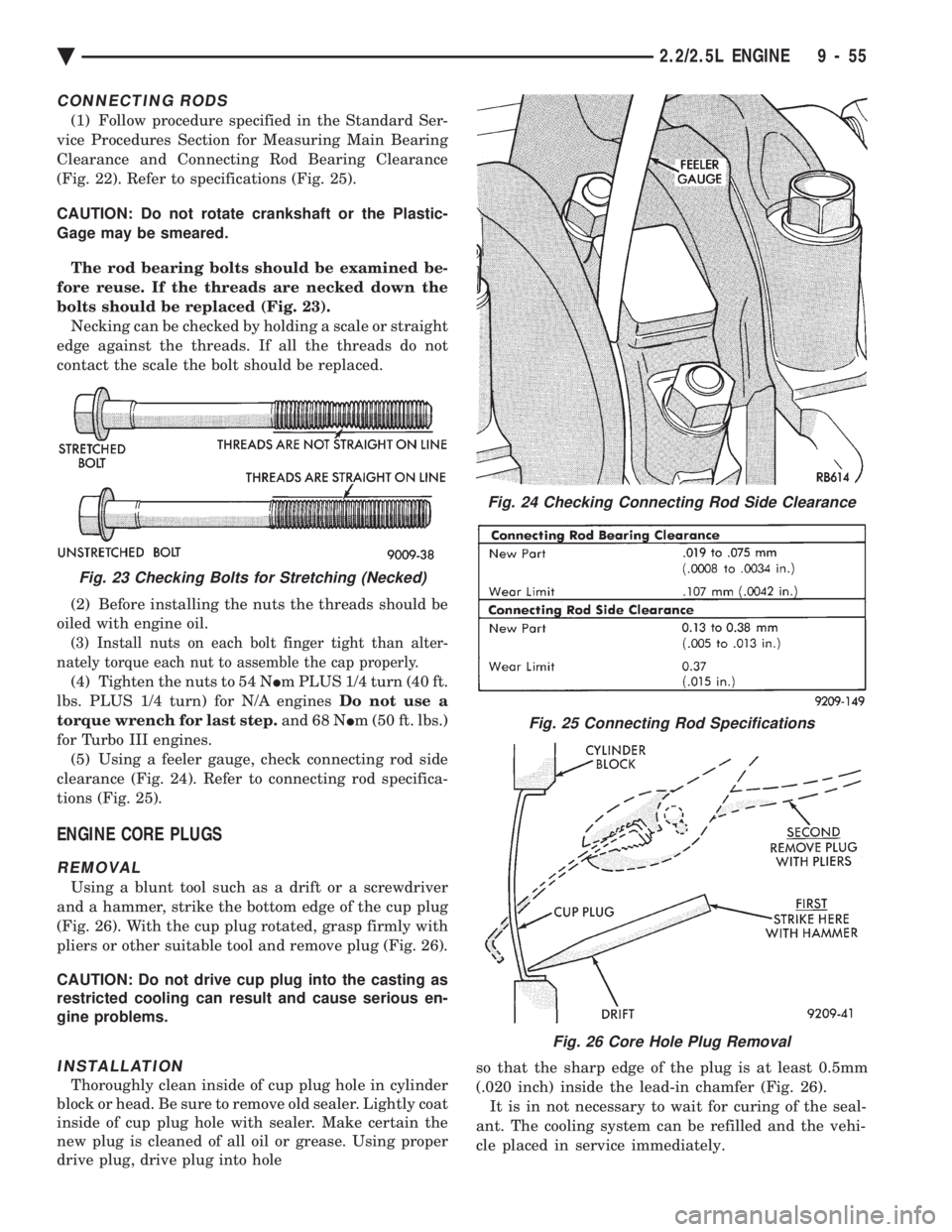
(Fig. 22). Refer to specifications (Fig. 25).
CAUTION: Do not rotate crankshaft or the Plastic-
Gage may be smeared.
The rod bearing bolts should be examined be-
fore reuse. If the threads are necked down the
bolts should be replaced (Fig. 23). Necking can be checked by holding a scale or straight
edge against the threads. If all the threads do not
contact the scale the bolt should be replaced.
(2) Before installing the nuts the threads should be
oiled with engine oil.
(3) Install nuts on each bolt finger tight than alter-
nately torque each nut to assemble the cap properly.
(4) Tighten the nuts to 54 N Im PLUS 1/4 turn (40 ft.
lbs. PLUS 1/4 turn) for N/A engines Do not use a
torque wrench for last step. and 68 NIm (50 ft. lbs.)
for Turbo III engines. (5) Using a feeler gauge, check connecting rod side
clearance (Fig. 24). Refer to connecting rod specifica-
tions (Fig. 25).
ENGINE CORE PLUGS
REMOVAL
Using a blunt tool such as a drift or a screwdriver
and a hammer, strike the bottom edge of the cup plug
(Fig. 26). With the cup plug rotated, grasp firmly with
pliers or other suitable tool and remove plug (Fig. 26).
CAUTION: Do not drive cup plug into the casting as
restricted cooling can result and cause serious en-
gine problems.
INSTALLATION
Thoroughly clean inside of cup plug hole in cylinder
block or head. Be sure to remove old sealer. Lightly coat
inside of cup plug hole with sealer. Make certain the
new plug is cleaned of all oil or grease. Using proper
drive plug, drive plug into hole so that the sharp edge of the plug is at least 0.5mm
(.020 inch) inside the lead-in chamfer (Fig. 26).
It is in not necessary to wait for curing of the seal-
ant. The cooling system can be refilled and the vehi-
cle placed in service immediately.
Fig. 24 Checking Connecting Rod Side Clearance
Fig. 25 Connecting Rod Specifications
Fig. 26 Core Hole Plug Removal
Fig. 23 Checking Bolts for Stretching (Necked)
Ä 2.2/2.5L ENGINE 9 - 55
Page 1624 of 2438
OIL PAN
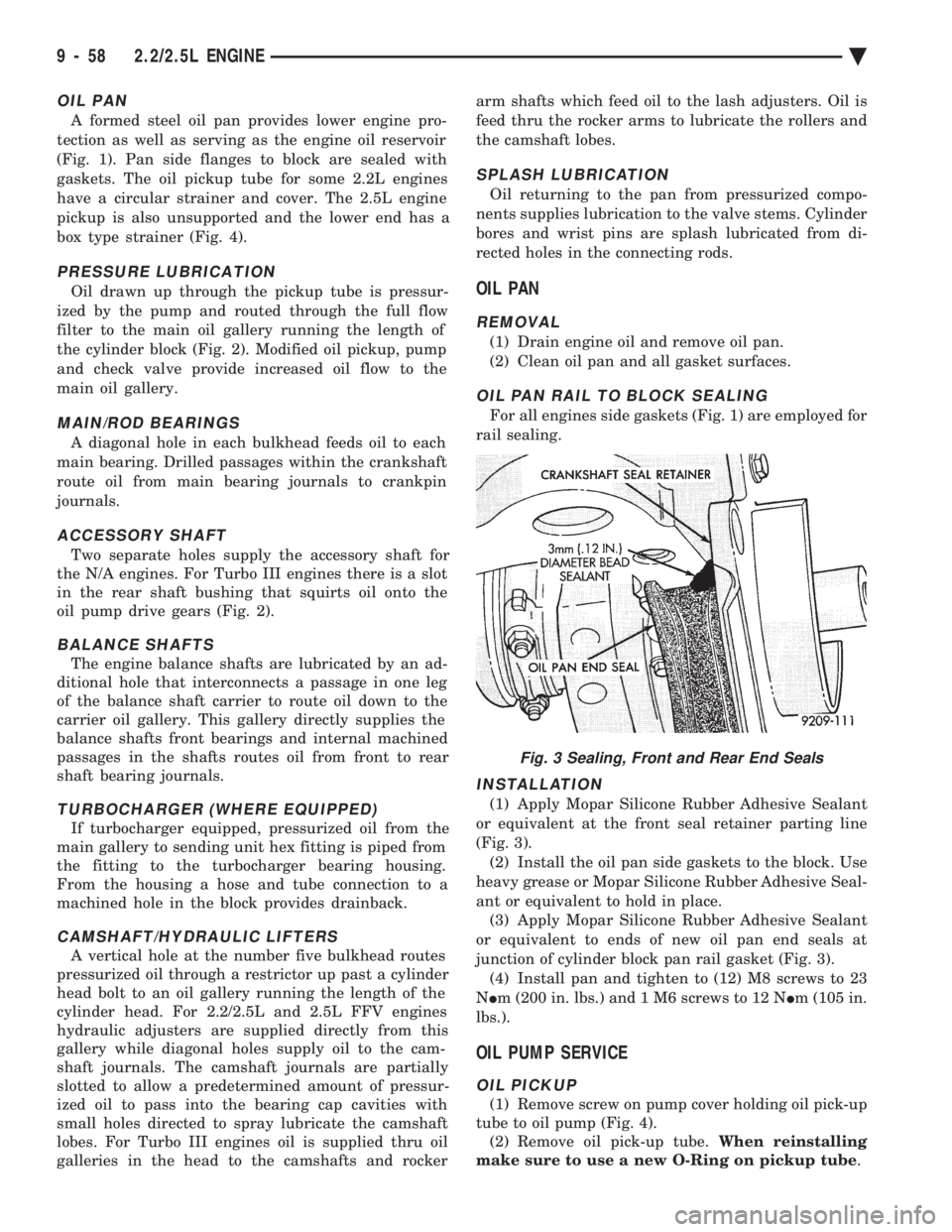
A formed steel oil pan provides lower engine pro-
tection as well as serving as the engine oil reservoir
(Fig. 1). Pan side flanges to block are sealed with
gaskets. The oil pickup tube for some 2.2L engines
have a circular strainer and cover. The 2.5L engine
pickup is also unsupported and the lower end has a
box type strainer (Fig. 4).
PRESSURE LUBRICATION
Oil drawn up through the pickup tube is pressur-
ized by the pump and routed through the full flow
filter to the main oil gallery running the length of
the cylinder block (Fig. 2). Modified oil pickup, pump
and check valve provide increased oil flow to the
main oil gallery.
MAIN/ROD BEARINGS
A diagonal hole in each bulkhead feeds oil to each
main bearing. Drilled passages within the crankshaft
route oil from main bearing journals to crankpin
journals.
ACCESSORY SHAFT
Two separate holes supply the accessory shaft for
the N/A engines. For Turbo III engines there is a slot
in the rear shaft bushing that squirts oil onto the
oil pump drive gears (Fig. 2).
BALANCE SHAFTS
The engine balance shafts are lubricated by an ad-
ditional hole that interconnects a passage in one leg
of the balance shaft carrier to route oil down to the
carrier oil gallery. This gallery directly supplies the
balance shafts front bearings and internal machined
passages in the shafts routes oil from front to rear
shaft bearing journals.
TURBOCHARGER (WHERE EQUIPPED)
If turbocharger equipped, pressurized oil from the
main gallery to sending unit hex fitting is piped from
the fitting to the turbocharger bearing housing.
From the housing a hose and tube connection to a
machined hole in the block provides drainback.
CAMSHAFT/HYDRAULIC LIFTERS
A vertical hole at the number five bulkhead routes
pressurized oil through a restrictor up past a cylinder
head bolt to an oil gallery running the length of the
cylinder head. For 2.2/2.5L and 2.5L FFV engines
hydraulic adjusters are supplied directly from this
gallery while diagonal holes supply oil to the cam-
shaft journals. The camshaft journals are partially
slotted to allow a predetermined amount of pressur-
ized oil to pass into the bearing cap cavities with
small holes directed to spray lubricate the camshaft
lobes. For Turbo III engines oil is supplied thru oil
galleries in the head to the camshafts and rocker arm shafts which feed oil to the lash adjusters. Oil is
feed thru the rocker arms to lubricate the rollers and
the camshaft lobes.
SPLASH LUBRICATION
Oil returning to the pan from pressurized compo-
nents supplies lubrication to the valve stems. Cylinder
bores and wrist pins are splash lubricated from di-
rected holes in the connecting rods.
OIL PAN
REMOVAL
(1) Drain engine oil and remove oil pan.
(2) Clean oil pan and all gasket surfaces.
OIL PAN RAIL TO BLOCK SEALING
For all engines side gaskets (Fig. 1) are employed for
rail sealing.
INSTALLATION
(1) Apply Mopar Silicone Rubber Adhesive Sealant
or equivalent at the front seal retainer parting line
(Fig. 3). (2) Install the oil pan side gaskets to the block. Use
heavy grease or Mopar Silicone Rubber Adhesive Seal-
ant or equivalent to hold in place. (3) Apply Mopar Silicone Rubber Adhesive Sealant
or equivalent to ends of new oil pan end seals at
junction of cylinder block pan rail gasket (Fig. 3). (4) Install pan and tighten to (12) M8 screws to 23
N Im (200 in. lbs.) and 1 M6 screws to 12 N Im (105 in.
lbs.).
OIL PUMP SERVICE
OIL PICKUP
(1) Remove screw on pump cover holding oil pick-up
tube to oil pump (Fig. 4). (2) Remove oil pick-up tube. When reinstalling
make sure to use a new O-Ring on pickup tube .
Fig. 3 Sealing, Front and Rear End Seals
9 - 58 2.2/2.5L ENGINE Ä
Page 1632 of 2438
3.0L ENGINE INDEX
page page
Accessory Drive Belt Service ................ 70
Auto Lash Adjuster ....................... 75
Camshaft Service ........................ 76
Checking Engine Oil Pressure ............... 93
Crankshaft and Cylinder Block, Assembly Service . 86
Cylinder Block ........................... 89
Cylinder Head ........................... 78
Cylinder Head and Camshaft Service ......... 75
Engine Assembly ......................... 69
Engine Lubrication System ................. 91
Engine Mounts .......................... 68 Engine Specifications
..................... 95
General Information ....................... 66
Oil Filter and Bracket ..................... 94
Oil Pan ................................ 92
Oil Pump Service ........................ 92
Piston and Connecting Rod Assembly Service . . . 82
Timing Belt InspectionÐIn Vehicle ............ 72
Timing Belt Service ....................... 72
Valve Service ........................... 80
GENERAL INFORMATION
ENGINE IDENTIFICATION NUMBER OR CODE
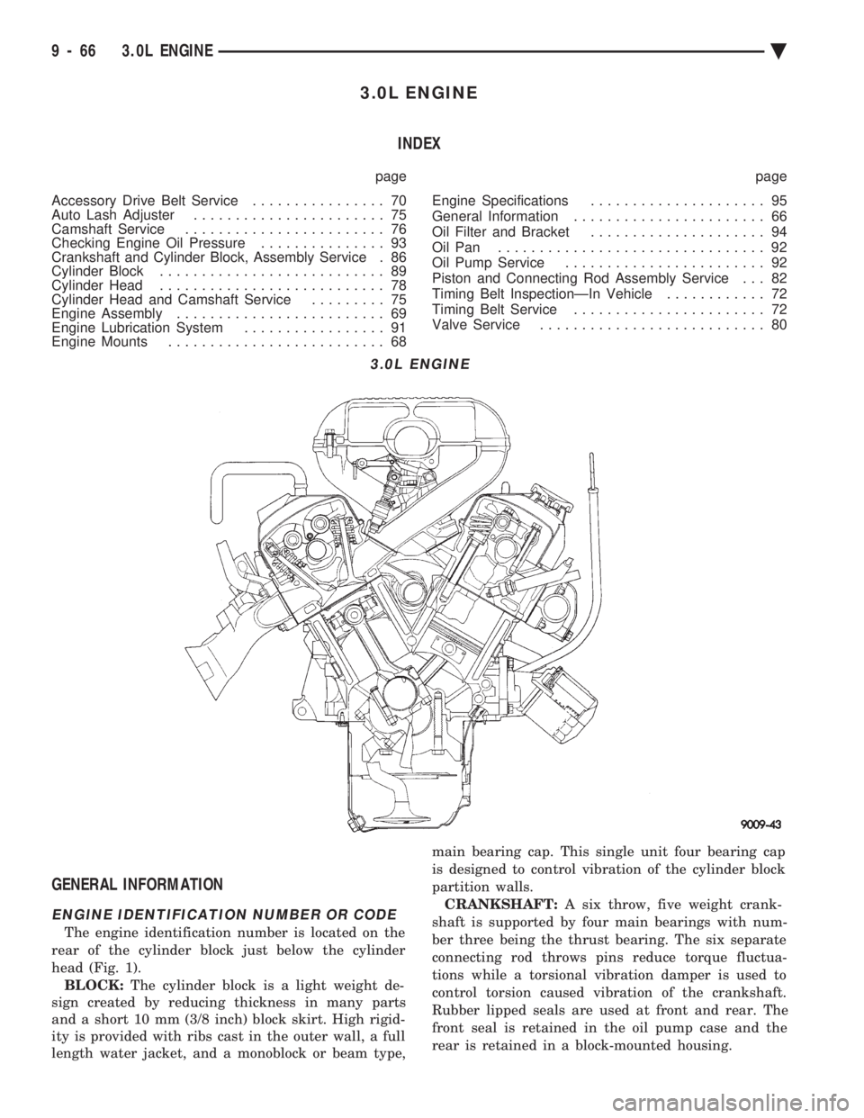
The engine identification number is located on the
rear of the cylinder block just below the cylinder
head (Fig. 1). BLOCK: The cylinder block is a light weight de-
sign created by reducing thickness in many parts
and a short 10 mm (3/8 inch) block skirt. High rigid-
ity is provided with ribs cast in the outer wall, a full
length water jacket, and a monoblock or beam type, main bearing cap. This single unit four bearing cap
is designed to control vibration of the cylinder block
partition walls.
CRANKSHAFT: A six throw, five weight crank-
shaft is supported by four main bearings with num-
ber three being the thrust bearing. The six separate
connecting rod throws pins reduce torque fluctua-
tions while a torsional vibration damper is used to
control torsion caused vibration of the crankshaft.
Rubber lipped seals are used at front and rear. The
front seal is retained in the oil pump case and the
rear is retained in a block-mounted housing.
3.0L ENGINE
9 - 66 3.0L ENGINE Ä
Page 1636 of 2438
(c) Remove LEFT insulator through bolt from in-
side wheelhouse or insulator bracket to transmis-
sion screws.
(22) Remove engine.
INSTALLATION
(1) Attach hoist and lower engine into engine com-
partment. (2) Align engine mounts and install but do not
tighten until all mounting bolts have been installed.
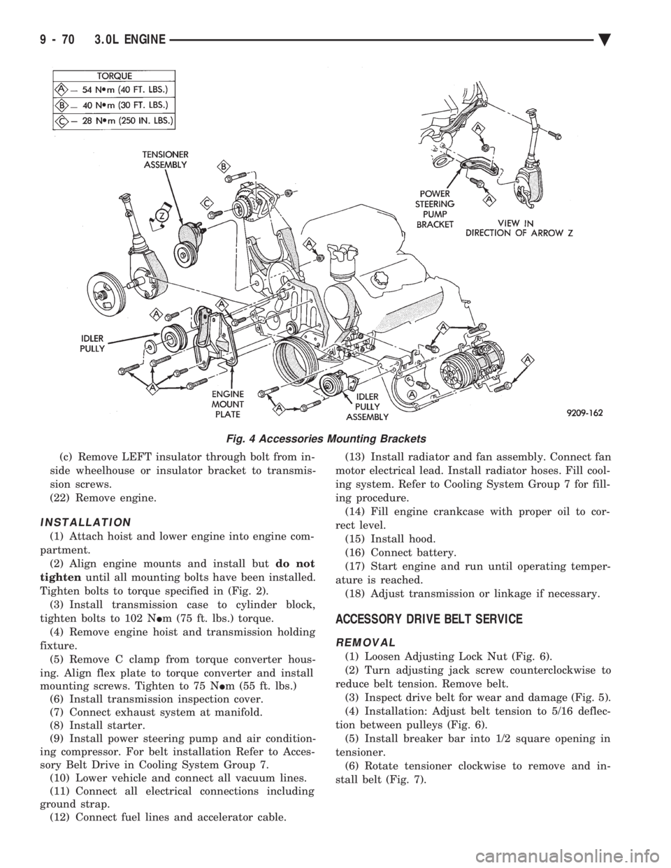
Tighten bolts to torque specified in (Fig. 2). (3) Install transmission case to cylinder block,
tighten bolts to 102 N Im (75 ft. lbs.) torque.
(4) Remove engine hoist and transmission holding
fixture. (5) Remove C clamp from torque converter hous-
ing. Align flex plate to torque converter and install
mounting screws. Tighten to 75 N Im (55 ft. lbs.)
(6) Install transmission inspection cover.
(7) Connect exhaust system at manifold.
(8) Install starter.
(9) Install power steering pump and air condition-
ing compressor. For belt installation Refer to Acces-
sory Belt Drive in Cooling System Group 7. (10) Lower vehicle and connect all vacuum lines.
(11) Connect all electrical connections including
ground strap. (12) Connect fuel lines and accelerator cable. (13) Install radiator and fan assembly. Connect fan
motor electrical lead. Install radiator hoses. Fill cool-
ing system. Refer to Cooling System Group 7 for fill-
ing procedure. (14) Fill engine crankcase with proper oil to cor-
rect level. (15) Install hood.
(16) Connect battery.
(17) Start engine and run until operating temper-
ature is reached. (18) Adjust transmission or linkage if necessary.
ACCESSORY DRIVE BELT SERVICE
REMOVAL
(1) Loosen Adjusting Lock Nut (Fig. 6).
(2) Turn adjusting jack screw counterclockwise to
reduce belt tension. Remove belt. (3) Inspect drive belt for wear and damage (Fig. 5).
(4) Installation: Adjust belt tension to 5/16 deflec-
tion between pulleys (Fig. 6). (5) Install breaker bar into 1/2 square opening in
tensioner. (6) Rotate tensioner clockwise to remove and in-
stall belt (Fig. 7).
Fig. 4 Accessories Mounting Brackets
9 - 70 3.0L ENGINE Ä
Page 1638 of 2438
(9) Mark support assembly to engine bracket if as-
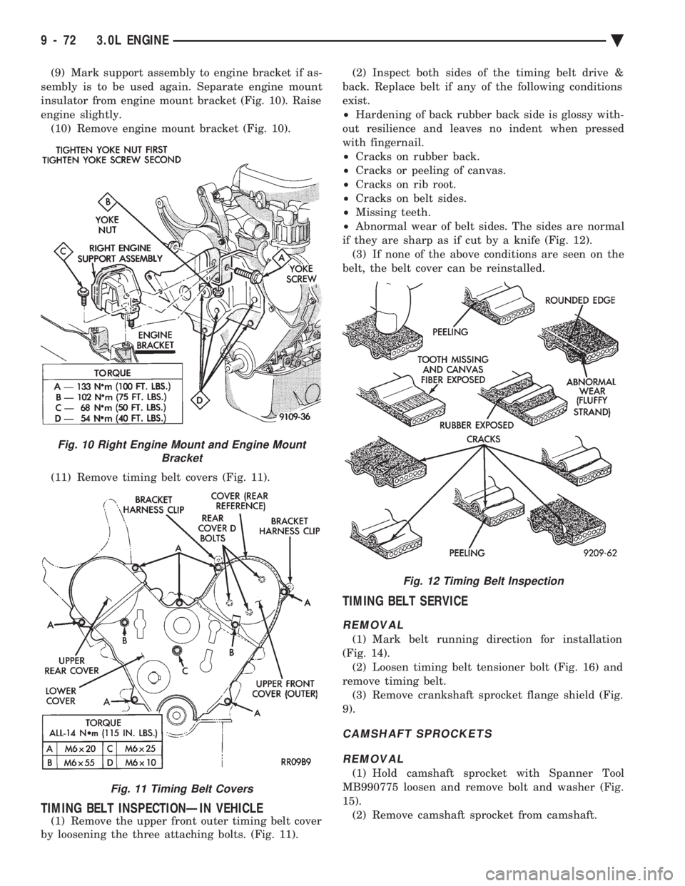
sembly is to be used again. Separate engine mount
insulator from engine mount bracket (Fig. 10). Raise
engine slightly. (10) Remove engine mount bracket (Fig. 10).
(11) Remove timing belt covers (Fig. 11).
TIMING BELT INSPECTIONÐIN VEHICLE
(1) Remove the upper front outer timing belt cover
by loosening the three attaching bolts. (Fig. 11). (2) Inspect both sides of the timing belt drive &
back. Replace belt if any of the following conditions
exist.
² Hardening of back rubber back side is glossy with-
out resilience and leaves no indent when pressed
with fingernail.
² Cracks on rubber back.
² Cracks or peeling of canvas.
² Cracks on rib root.
² Cracks on belt sides.
² Missing teeth.
² Abnormal wear of belt sides. The sides are normal
if they are sharp as if cut by a knife (Fig. 12). (3) If none of the above conditions are seen on the
belt, the belt cover can be reinstalled.
TIMING BELT SERVICE
REMOVAL
(1) Mark belt running direction for installation
(Fig. 14). (2) Loosen timing belt tensioner bolt (Fig. 16) and
remove timing belt. (3) Remove crankshaft sprocket flange shield (Fig.
9).
CAMSHAFT SPROCKETS
REMOVAL
(1) Hold camshaft sprocket with Spanner Tool
MB990775 loosen and remove bolt and washer (Fig.
15). (2) Remove camshaft sprocket from camshaft.
Fig. 10 Right Engine Mount and Engine Mount Bracket
Fig. 11 Timing Belt Covers
Fig. 12 Timing Belt Inspection
9 - 72 3.0L ENGINE Ä
Page 1641 of 2438
CYLINDER HEAD AND CAMSHAFT SERVICE
CYLINDER HEAD COVER REMOVE
(1) Remove air cleaner assembly.
(2) Disconnect battery and relocate spark plug
wires. (3) Remove vacuum connections.
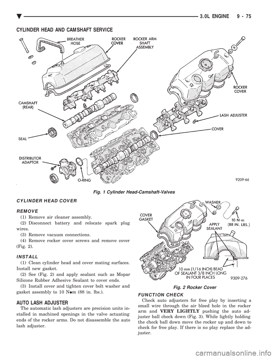
(4) Remove rocker cover screws and remove cover
(Fig. 2).
INSTALL
(1) Clean cylinder head and cover mating surfaces.
Install new gasket. (2) See (Fig. 2) and apply sealant such as Mopar
Silicone Rubber Adhesive Sealant to cover ends. (3) Install cover and tighten cover bolt washer and
gasket assembly to 10 N Im (88 in. lbs.).
AUTO LASH ADJUSTER
The automatic lash adjusters are precision units in-
stalled in machined openings in the valve actuating
ends of the rocker arms. Do not disassemble the auto
lash adjuster.
FUNCTION CHECK
Check auto adjusters for free play by inserting a
small wire through the air bleed hole in the rocker
arm and VERY LIGHTLY pushing the auto ad-
juster ball check down (Fig. 3). While lightly holding
the check ball down move the rocker up and down to
check for free play. If there is no play replace the ad-
juster.
Fig. 1 Cylinder Head-Camshaft-Valves
Fig. 2 Rocker Cover
Ä 3.0L ENGINE 9 - 75
Page 1642 of 2438
CAMSHAFT SERVICE
SEE AUTO LASH ADJUSTER FUNCTION CHECK BEFORE DISASSEMBLY
REMOVAL
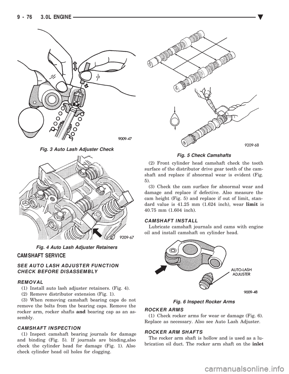
(1) Install auto lash adjuster retainers. (Fig. 4).
(2) Remove distributor extension (Fig. 1).
(3) When removing camshaft bearing caps do not
remove the bolts from the bearing caps. Remove the
rocker arm, rocker shafts andbearing cap as an as-
sembly.
CAMSHAFT INSPECTION
(1) Inspect camshaft bearing journals for damage
and binding (Fig. 5). If journals are binding,also
check the cylinder head for damage (Fig. 1). Also
check cylinder head oil holes for clogging. (2) Front cylinder head camshaft check the tooth
surface of the distributor drive gear teeth of the cam-
shaft and replace if abnormal wear is evident (Fig.
5). (3) Check the cam surface for abnormal wear and
damage and replace if defective. Also measure the
cam height (Fig. 5) and replace if out of limit, stan-
dard value is 41.25 mm (1.624 inch), wear limitis
40.75 mm (1.604 inch).
CAMSHAFT INSTALL
Lubricate camshaft journals and cams with engine
oil and install camshaft on cylinder head.
ROCKER ARMS
(1) Check rocker arms for wear or damage (Fig. 6).
Replace as necessary. Also see Auto Lash Adjuster.
ROCKER ARM SHAFTS
The rocker arm shaft is hollow and is used as a lu-
brication oil duct. The rocker arm shaft on the inlet
Fig. 3 Auto Lash Adjuster Check
Fig. 4 Auto Lash Adjuster Retainers
Fig. 5 Check Camshafts
Fig. 6 Inspect Rocker Arms
9 - 76 3.0L ENGINE Ä