1993 CHEVROLET DYNASTY dimensions
[x] Cancel search: dimensionsPage 100 of 2438
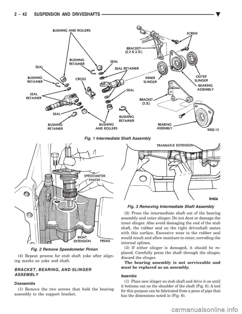
(4) Repeat process for stub shaft yoke after align-
ing marks on yoke and shaft.
BRACKET, BEARING, AND SLINGER ASSEMBLY
Disassemble
(1) Remove the two screws that hold the bearing
assembly to the support bracket. (2) Press the intermediate shaft out of the bearing
assembly and outer slinger. Do not dent or damage the
inner slinger. Also avoid damaging the end of the stub
shaft, the rubber seal on the right driveshaft mates
with this surface. Excessive wear to the rubber seal
would result and allow moisture to enter, corroding the
internal splines. (3) If either slinger is damaged, it should be re-
placed. Carefully press the shaft through the slinger,
discard the slinger. The bearing assembly is not serviceable and
must be replaced as an assembly.
Assemble(1) Place new slinger on stub shaft and drive it on until
it bottoms out on the shoulder of the shaft (Fig. 6). A tool
for this purpose can be fabricated from a piece of pipe that
has the dimensions noted in (Fig. 6).
Fig. 1 Intermediate Shaft Assembly
Fig. 2 Remove Speedometer Pinion
Fig. 3 Removing Intermediate Shaft Assembly
2 - 42 SUSPENSION AND DRIVESHAFTS Ä
Page 107 of 2438
mount have been loosened for any reason, or if vehicle
has experienced front structural damage, driveshaft
lengths must be checked and corrected, if required. A
shorter than required driveshaft length can result in ob-
jectionable noise. A longer than required driveshaft
length may result in potential damage.
Use of the following procedure will ensure satisfac-
tory driveshaft engagement under all normal vehicle
operating conditions. (1) The vehicle must be completely assembled.
Front wheels must be properly aligned and in the
straight ahead position. The vehicle must be in a po-
sition so that the full weight of the body is distrib-
uted to all four tires. A platform hoist, or front end
alignment rack, is recommended.
(2) Using a tape measure or other suitable measuring
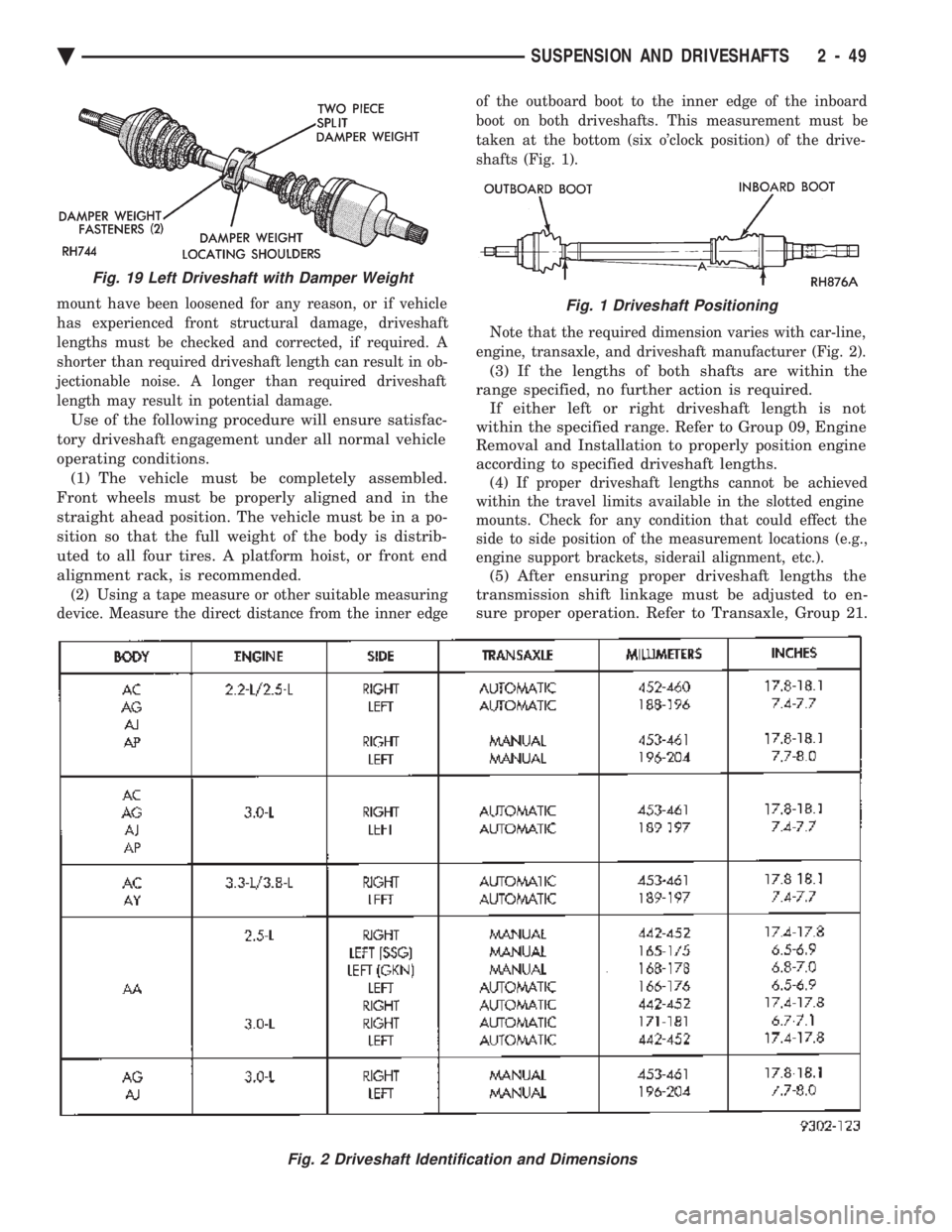
device. Measure the direct distance from the inner edge of the outboard boot to the inner edge of the inboard
boot on both driveshafts. This measurement must be
taken at the bottom (six o'clock position) of the drive-
shafts (Fig. 1).
Note that the required dimension varies with car-line,
engine, transaxle, and driveshaft manufacturer (Fig. 2).
(3) If the lengths of both shafts are within the
range specified, no further action is required. If either left or right driveshaft length is not
within the specified range. Refer to Group 09, Engine
Removal and Installation to properly position engine
according to specified driveshaft lengths.
(4) If proper driveshaft lengths cannot be achieved
within the travel limits available in the slotted engine
mounts. Check for any condition that could effect the
side to side position of the measurement locations (e.g.,
engine support brackets, siderail alignment, etc.).
(5) After ensuring proper driveshaft lengths the
transmission shift linkage must be adjusted to en-
sure proper operation. Refer to Transaxle, Group 21.
Fig. 2 Driveshaft Identification and Dimensions
Fig. 19 Left Driveshaft with Damper Weight
Fig. 1 Driveshaft Positioning
Ä SUSPENSION AND DRIVESHAFTS 2 - 49
Page 162 of 2438
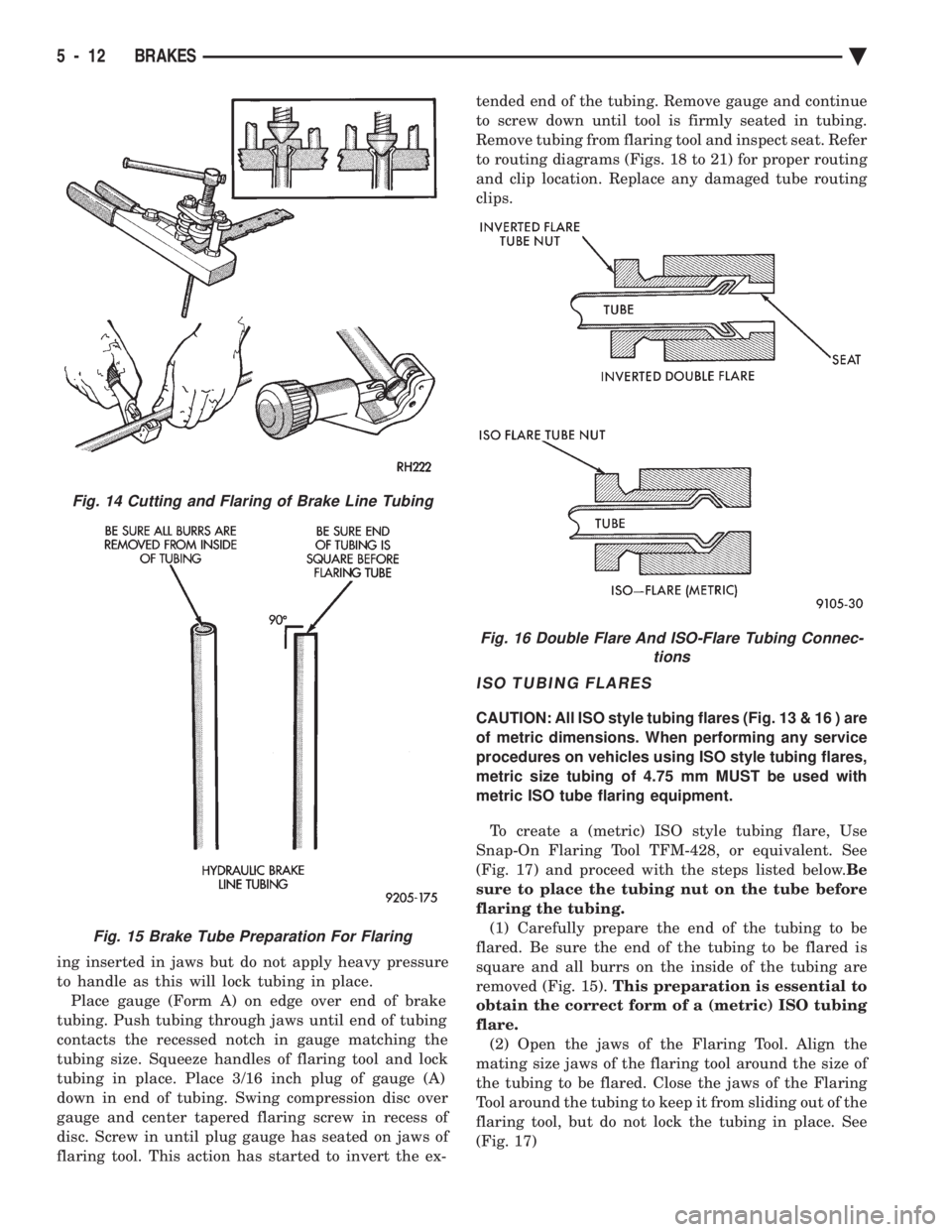
ing inserted in jaws but do not apply heavy pressure
to handle as this will lock tubing in place.Place gauge (Form A) on edge over end of brake
tubing. Push tubing through jaws until end of tubing
contacts the recessed notch in gauge matching the
tubing size. Squeeze handles of flaring tool and lock
tubing in place. Place 3/16 inch plug of gauge (A)
down in end of tubing. Swing compression disc over
gauge and center tapered flaring screw in recess of
disc. Screw in until plug gauge has seated on jaws of
flaring tool. This action has started to invert the ex- tended end of the tubing. Remove gauge and continue
to screw down until tool is firmly seated in tubing.
Remove tubing from flaring tool and inspect seat. Refer
to routing diagrams (Figs. 18 to 21) for proper routing
and clip location. Replace any damaged tube routing
clips.
ISO TUBING FLARES
CAUTION: All ISO style tubing flares (Fig. 13 & 16 ) are
of metric dimensions. When performing any service
procedures on vehicles using ISO style tubing flares,
metric size tubing of 4.75 mm MUST be used with
metric ISO tube flaring equipment.
To create a (metric) ISO style tubing flare, Use
Snap-On Flaring Tool TFM-428, or equivalent. See
(Fig. 17) and proceed with the steps listed below. Be
sure to place the tubing nut on the tube before
flaring the tubing. (1) Carefully prepare the end of the tubing to be
flared. Be sure the end of the tubing to be flared is
square and all burrs on the inside of the tubing are
removed (Fig. 15). This preparation is essential to
obtain the correct form of a (metric) ISO tubing
flare. (2) Open the jaws of the Flaring Tool. Align the
mating size jaws of the flaring tool around the size of
the tubing to be flared. Close the jaws of the Flaring
Tool around the tubing to keep it from sliding out of the
flaring tool, but do not lock the tubing in place. See
(Fig. 17)
Fig. 14 Cutting and Flaring of Brake Line Tubing
Fig. 15 Brake Tube Preparation For Flaring
Fig. 16 Double Flare And ISO-Flare Tubing Connec- tions
5 - 12 BRAKES Ä
Page 181 of 2438
FRONT DISC BRAKES INDEX
page page
General Information ....................... 31
Service Precautions ....................... 34 Shoe and Lining Wear
.................... 33
GENERAL INFORMATION
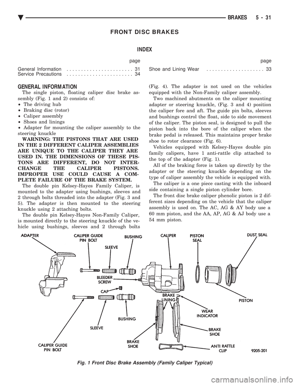
The single piston, floating caliper disc brake as-
sembly (Fig. 1 and 2) consists of:
² The driving hub
² Braking disc (rotor)
² Caliper assembly
² Shoes and linings
² Adapter for mounting the caliper assembly to the
steering knuckle WARNING: THE PISTONS THAT ARE USED
IN THE 2 DIFFERENT CALIPER ASSEMBLIES
ARE UNIQUE TO THE CALIPER THEY ARE
USED IN. THE DIMENSIONS OF THESE PIS-
TONS ARE DIFFERENT, DO NOT INTER-
CHANGE THE CALIPER PISTONS.
IMPROPER USE COULD CAUSE A COM-
PLETE FAILURE OF THE BRAKE SYSTEM. The double pin Kelsey-Hayes Family Caliper, is
mounted to the adapter using bushings, sleeves and
2 through bolts threaded into the adapter (Fig. 3 and
5). The adapter is then mounted to the steering
knuckle using 2 attaching bolts. The double pin Kelsey-Hayes Non-Family Caliper,
is mounted directly to the steering knuckle of the ve-
hicle using bushings, sleeves and 2 through bolts (Fig. 4). The adapter is not used on the vehicles
equipped with the Non-Family caliper assembly.
Two machined abutments on the caliper mounting
adapter or steering knuckle, (Fig. 3 and 4) position
the caliper fore and aft. The guide pin bolts, sleeves
and bushings control the float, side to side movement
of the caliper. The piston seal, is designed to pull the
piston back into the bore of the caliper when the
brake pedal is released. This maintains proper brake
shoe to rotor clearance (Fig. 6). Vehicles equipped with Kelsey-Hayes double pin
family calipers, have 1 anti-rattle clip attached to
the top of the adapter (Fig. 1). All of the braking force is taken up directly by the
adapter or the steering knuckle depending on the
type of caliper assembly the vehicle is equipped with. The caliper is a one piece casting with the inboard
side containing a single piston cylinder bore. The front disc brake caliper phenolic piston is 2 dif-
ferent sizes depending on the vehicle that the caliper
assembly is used on. The AC, AG & AY body use a
60 mm piston, and the AA, AP, AG & AJ body use a
54 mm piston.
Fig. 1 Front Disc Brake Assembly (Family Caliper Typical)
Ä BRAKES 5 - 31
Page 445 of 2438

When testing secondary cables for punctures and
cracks with an oscilloscope follow the equipment
manufacturers instructions. If an oscilloscope is not available, secondary cables
can be tested as follows:
CAUTION: Do not leave any one spark plug cable
disconnected any longer than necessary during test-
ing. Excessive heat could damage the catalytic con-
verter. Total test time must not exceed ten minutes.
(a) With the engine not running, connect one end
of a test probe to a good ground. Use a probe made of
insulated wire with insulated alligator clips on each
end. (b) With engine running, move test probe along
entire length of all cables (approximately 0 to 1/8
inch gap). If punctures or cracks are present there
will be a noticeable spark jump from the faulty area
to the probe. Check the coil cable the same way.
Replace cracked, leaking or faulty cables.
When replacing cables, install the new high
tension cable and nipple assembly over cap or
coil tower. When entering the terminal into the
tower, push lightly, then pinch the large diam-
eter of nipple to release air trapped between the
nipple and tower. Continue pushing on the cable
and nipple until cables are properly seated in the
cap towers. A snap should be heard as terminal
goes into place. Use the same procedure to install cable in coil tower.
Wipe the spark plug insulator clean before reinstalling
cable and cover. Use the following procedure when removing the high
tension cable from the spark plug. First, remove the
cable from the retaining bracket. Then grasp the ter-
minal as close as possible to the spark plug. Rotate the
cover and pull the cable straight back. Pulling on the
cable itself will damage the conductor and termi-
nal connection. Do not use pliers and do not pull
the cable at an angle. Doing so will damage the
insulation, cable terminal or the spark plug in-
sulator. Wipe spark plug insulator clean before
reinstalling cable and cover. Resistance type cable is identified by the words
Electronic Suppression printed on the cable jacket.
Use an ohmmeter to check resistance type cable for
open circuits, loose terminals or high resistance as
follows: (a) Remove cable from spark plug.
(b) Lift distributor cap from distributor with
cables intact. Do not remove cables from cap. The
cables must be removed from the spark plugs. (c) Connect the ohmmeter between spark plug end
terminal and the corresponding electrode inside the
cap, make sure ohmmeter probes are in good contact.
Resistance should be within tolerance shown in the cable resistance chart. If resistance is
not within tolerance, remove cable at cap tower
and check the cable. If resistance is still not within
tolerance, replace cable assembly. Test all spark
plug cables in same manner.
To test coil to distributor cap high tension cable,
remove distributor cap with the cable intact. Do not
remove cable from the cap. Connect the ohmmeter
between center contact in the cap and remove the ca-
ble at coil tower and check cable resistance. If resis-
tance is not within tolerance, replace the cable.
SPARK PLUGS
Resistor spark plugs are used in all engines and
have resistance values of 6,000 to 20,000 ohms when
checked with at least a 1000 volt tester. Remove the spark plugs and examine them for
burned electrodes and fouled, cracked or broken por-
celain insulators. Keep plugs arranged in the order
in which they were removed from the engine. An iso-
lated plug displaying an abnormal condition indi-
cates that a problem exists in the corresponding
cylinder. Replace spark plugs at the intervals recom-
mended in Group O. Undamaged low milage spark plugs can be cleaned
and reused. Refer to the Spark Plug Condition sec-
tion of this group. After cleaning, file the center elec-
trode flat with a small point file or jewelers file.
Adjust the gap between the electrodes (Fig. 6) to the
dimensions specified in the chart at the end of this
section. Always tighten spark plugs to the specified torque.
Over tightening can cause distortion and change
spark plug gap. Tighten spark plugs to 28 N Im (20 ft.
lbs.) torque.
SPARK PLUG CONDITION
NORMAL OPERATING CONDITIONS
The few deposits present will be probably light tan
or slightly gray in color with most grades of commer-
cial gasoline (Fig. 7). There will not be evidence of
electrode burning. Gap growth will not average more
than approximately 0.025 mm (.001 in) per 1600 km
(1000 miles) of operation. Spark plugs that have nor-
mal wear can usually be cleaned, have the electrodes
filed and regapped, and then reinstalled. Some fuel refiners in several areas of the United
States have introduced a manganese additive (MMT)
CABLE RESISTANCE CHART
Ä IGNITION SYSTEMS 8D - 3
Page 468 of 2438

tance. The cables provide suppression of radio fre-
quency emissions from the ignition system.Check the spark plug cable connections for good
contact at the coil and distributor cap towers and at
the spark plugs. Terminals should be fully seated.
The nipples and spark plug covers should be in good
condition. Nipples should fit tightly on the coil and
distributor cap towers and spark plug cover should
fit tight around spark plug insulators. Loose cable
connections can cause ignition malfunctions by per-
mitting water to enter the towers, corroding, and in-
creasing resistance.
SPARK PLUGS
The 2.2L Turbo III, 3.3L and 3.8L engines use re-
sistor spark plugs. They have resistance values of
6,000 to 20,000 ohms when checked with at least a
1000 volt tester. Remove the spark plugs and examine them for
burned electrodes and fouled, cracked or broken por-
celain insulators. Keep plugs arranged in the order
in which they were removed from the engine. An iso-
lated plug displaying an abnormal condition indi-
cates that a problem exists in the corresponding
cylinder. Replace spark plugs at the intervals recom-
mended in Group O. Spark plugs that have low milage may be cleaned
and reused if not otherwise defective. Refer to the
Spark Plug Condition section of this group. After
cleaning, file the center electrode flat with a small
point file or jewelers file. Adjust the gap between the
electrodes (Fig. 8) to the dimensions specified in the
chart at the end of this section.
Always tighten spark plugs to the specified torque.
Over tightening can cause distortion and change
spark plug gap. Tighten 2.2L Turbo III, 3.3L and
3.8L spark plugs to 28 N Im (20 ft. lbs.) torque.
SPARK PLUG CONDITION
NORMAL OPERATING CONDITIONS
The few deposits present will be probably light tan
or slightly gray in color with most grades of commer-
cial gasoline (Fig. 9). There will not be evidence of
electrode burning. Gap growth will not average more
than approximately 0.025 mm (.001 in) per 1600 km
(1000 miles) of operation. Spark plugs that have nor-
Fig. 6 Spark Plug Wire RoutingÐ3.3L and 3.8L Engines
Fig. 7 Powertrain Control Module (PCM)
Fig. 8 Setting Spark Plug Electrode GapÐTypical
8D - 26 IGNITION SYSTEMS Ä
Page 1595 of 2438
(2) Inspect each valve spring for squareness with a
steel square and surface plate, test springs from both
ends. If the spring is more than 1.5mm (1/16 inch)
out of square, install a new spring.
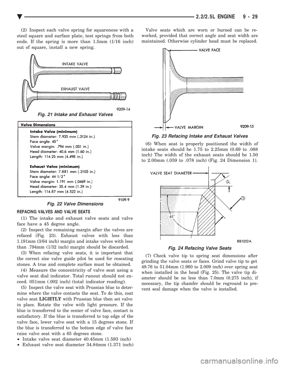
REFACING VALVES AND VALVE SEATS (1) The intake and exhaust valve seats and valve
face have a 45 degree angle.
(2) Inspect the remaining margin after the valves are
refaced (Fig. 23). Exhaust valves with less than
1.191mm (3/64 inch) margin and intake valves with less
than .794mm (1/32 inch) margin should be discarded. (3) When refacing valve seats, it is important that
the correct size valve guide pilot be used for reseating
stones. A true and complete surface must be obtained.
(4) Measure the concentricity of valve seat using a
valve seat dial indicator. Total runout should not ex-
ceed. 051mm (.002 inch) (total indicator reading).
(5) Inspect the valve seat with Prussian blue to deter-
mine where the valve contacts the seat. To do this, coat
valve seat LIGHTLY with Prussian blue then set valve
in place. Rotate the valve with light pressure. If the
blue is transferred to the center of valve face, contact is
satisfactory. If the blue is transferred to top edge of the
valve face, lower valve seat with a 15 degrees stone. If
the blue is transferred to the bottom edge of valve face
raise valve seat with a 65 degrees stone.
² Intake valve seat diameter 40.45mm (1.593 inch)
² Exhaust valve seat diameter 34.84mm (1.371 inch)
Valve seats which are worn or burned can be re-
worked, provided that correct angle and seat width are
maintained. Otherwise cylinder head must be replaced.
(6) When seat is properly positioned the width of
intake seats should be 1.75 to 2.25mm (0.69 to .088
inch) The width of the exhaust seats should be 1.50
to 2.00mm (.059 to .078 inch) (Fig. 24 Dimension 1).
(7) Check valve tip to spring seat dimensions after
grinding the valve seats or faces. Grind valve tip to get
49.76 to 51.04mm (1.960 to 2.009 inch) over spring seat
when installed in the head (Fig. 25). The valve tip di-
ameter should be no less than 7.0mm (0.275 inch), if
necessary, the tip chamfer should be reground to pre-
vent seal damage when the valve is installed.
Fig. 21 Intake and Exhaust Valves
Fig. 22 Valve Dimensions
Fig. 23 Refacing Intake and Exhaust Valves
Fig. 24 Refacing Valve Seats
Ä 2.2/2.5L ENGINE 9 - 29
Page 1596 of 2438
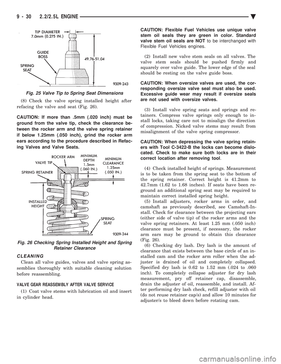
(8) Check the valve spring installed height after
refacing the valve and seat (Fig. 26).
CAUTION: If more than .5mm (.020 inch) must be
ground from the valve tip, check the clearance be-
tween the rocker arm and the valve spring retainer
if below 1.25mm (.050 inch), grind the rocker arm
ears according to the procedure described in Refac-
ing Valves and Valve Seats.
CLEANING
Clean all valve guides, valves and valve spring as-
semblies thoroughly with suitable cleaning solution
before reassembling.
VALVE GEAR REASSEMBLY AFTER VALVE SERVICE (1) Coat valve stems with lubrication oil and insert
in cylinder head. CAUTION: Flexible Fuel Vehicles use unique valve
stem oil seals they are green in color. Standard
valve stem oil seals are NOT to be interchanged with
Flexible Fuel Vehicles engines.
(2) Install new valve stem seals on all valves. The
valve stem seals should be pushed firmly and
squarely over valve guide. The lower edge of the seal
should be resting on the valve guide boss.
CAUTION: When oversize valves are used, the cor-
responding oversize valve seal must also be used.
Excessive guide wear may result if oversize seals
are not used with oversize valves.
(3) Install valve spring seats and springs and re-
tainers. Compress valve springs only enough to in-
stall locks, taking care not to misalign the direction
of compression. Nicked valve stems may result from
misalignment of the valve spring compressor.
CAUTION: When depressing the valve spring retain-
ers with Tool C-3422-B the locks can become dislo-
cated. Check to make sure both locks are in their
correct location after removing tool .
(4) Check installed height of springs. Measurement
is to be taken from the spring seat to the bottom of
the spring retainer. Correct height is 41.2mm to
42.7mm (1.62 to 1.68 inches). If seats have been re-
ground an additional spring seat may be required to
maintain correct installed spring height. (5) Install adjusters, rocker arms in order, and
camshaft as previously described, see Camshaft-In-
stall. Check for clearance between the projecting ears
(either side of valve tip) of the rocker arms and the
valve spring retainers. At least 1.25 mm (.050 inch)
clearance must be present, if necessary, the rocker
arm ears may be ground to obtain this clearance
(Fig. 26). (6) Checking dry lash. Dry lash is the amount of
clearance that exists between the base circle of an in-
stalled cam and the rocker arm roller when the ad-
juster is drained of oil and completely collapsed.
Specified dry lash is 0.62 to 1.52 mm (.024 to .060
inch). To completely collapse adjuster for dry lash
measurement, pry off retainer cap, disassemble,
drain the adjuster of oil, reassemble, and install. Af-
ter performing dry lash check, refill adjuster with oil
(do not reuse retainer cap/s) and allow 10 minutes for
adjuster/s to bleed down before rotating cam.
Fig. 25 Valve Tip to Spring Seat Dimensions
Fig. 26 Checking Spring Installed Height and Spring Retainer Clearance
9 - 30 2.2/2.5L ENGINE Ä