1993 CHEVROLET DYNASTY maintenance
[x] Cancel search: maintenancePage 18 of 2438

GROUP TAB LOCATOR
Introduction
0Lubrication and Maintenance
2Suspension/Driveshafts
5Brakes
6Manual Transaxle Clutch
7Cooling System
9Engine
11Exhaust System and Intake Manifold
13Frame and Bumpers
19Steering
21Transaxle
22Wheels/Tires
23Body
24Heating/Air Conditioning
Component and System Index
Service Manual Comment Forms (Rear of Manual)
Page 31 of 2438

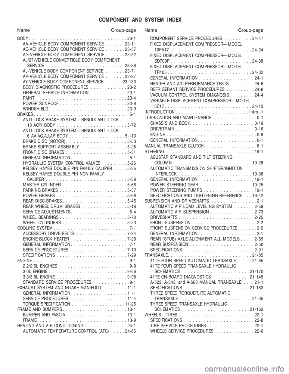
COMPONENT AND SYSTEM INDEX
Name Group-page Name Group-page
BODY ................................... 23-1
AA-VEHICLE BODY COMPONENT SERVICE .......23-11
AC-VEHICLE BODY COMPONENT SERVICE .......23-37
AG-VEHICLE BODY COMPONENT SERVICE .......23-52
AJ/27-VEHICLE CONVERTIBLE BODY COMPONENT SERVICE ............................ 23-86
AJ-VEHICLE BODY COMPONENT SERVICE .......23-71
AP-VEHICLE BODY COMPONENT SERVICE .......23-97
AY-VEHICLE BODY COMPONENT SERVICE .......23-133
BODY DIAGNOSTIC PROCEDURES .............23-2
GENERAL SERVICE INFORMATION .............23-1
PAINT ................................. 23-4
POWER SUNROOF ........................ 23-6
WINDSHIELD ............................ 23-9
BRAKES ..................................5-1
ANTI-LOCK BRAKE SYSTEMÐBENDIX ANTI-LOCK 10 AC/Y BODY ......................... 5-72
ANTI-LOCK BRAKE SYSTEMÐBENDIX ANTI-LOCK 6 AA,AG,AJ,AP BODY .................... 5-113
BRAKE DISC (ROTOR) ...................... 5-53
BRAKE SUPPORT ASSEMBLY .................5-25
FRONT DISC BRAKES ...................... 5-31
GENERAL INFORMATION .....................5-1
HYDRAULIC SYSTEM CONTROL VALVES .........5-26
KELSEY HAYES DOUBLE PIN FAMILY CALIPER .....5-35
KELSEY HAYES DOUBLE PIN NON-FAMILY CALIPER ............................. 5-38
MASTER CYLINDER ....................... 5-66
PARKING BRAKES ........................ 5-57
POWER BRAKES ......................... 5-68
REAR DISC BRAKES ....................... 5-45
REAR WHEEL DRUM BRAKES ................5-18
SERVICE ADJUSTMENTS .....................5-4
WHEEL BEARINGS ........................ 5-70
WHEEL CYLINDERS ....................... 5-23
COOLING SYSTEM ...........................7-1
ACCESSORY DRIVE BELTS ................... 7-24
ENGINE BLOCK HEATER .................... 7-28
GENERAL INFORMATION .....................7-1
SERVICE PROCEDURES ..................... 7-10
SPECIFICATIONS ......................... 7-29
ENGINE ..................................9-1
2.2/2.5L ENGINES .........................9-8
3.0L ENGINE ............................ 9-66
3.3/3.8L ENGINE ......................... 9-98
STANDARD SERVICE PROCEDURES .............9-1
EXHAUST SYSTEM AND INTAKE MANIFOLD .........11-1
GENERAL INFORMATION .................... 11-1
SERVICE PROCEDURES ..................... 11-4
TORQUE SPECIFICATION ................... 11-25
FRAME AND BUMPERS ....................... 13-1
BUMPER AND FASCIA ...................... 13-1
FRAME ................................ 13-9
HEATING AND AIR CONDITIONING ...............24-1
AUTOMATIC TEMPERATURE CONTROL (ATC) .....24-66 COMPONENT SERVICE PROCEDURES
..........24-47
FIXED DISPLACEMENT COMPRESSORÐMODEL 10PA17............................. 24-24
FIXED DISPLACEMENT COMPRESSORÐMODEL SD709P ............................. 24-38
FIXED DISPLACEMENT COMPRESSORÐMODEL TR105 .............................. 24-32
GENERAL INFORMATION .................... 24-1
HEATER AND A/C PERFORMANCE TESTS .........24-6
REFRIGERANT SERVICE PROCEDURES ..........24-8
VACUUM CONTROL SYSTEM DIAGNOSIS .........24-4
VARIABLE DISPLACEMENT COMPRESSORÐMODEL 6C17 ............................... 24-13
INTRODUCTION .......................... Intro.-1
LUBRICATION AND MAINTENANCE ................0-1
CHASSIS AND BODY ....................... 0-19
DRIVETRAIN ............................ 0-16
ENGINE ................................0-8
GENERAL INFORMATION .....................0-1
MANUAL TRANSAXLE CLUTCH ...................6-1
STEERING ................................ 19-1
ACUSTAR STANDARD AND TILT STEERING COLUMN ............................ 19-28
AUTOMATIC TRANSMISSION SHIFTER/IGNITION INTERLOCK .......................... 19-36
GENERAL INFORMATION .................... 19-1
POWER STEERING GEAR ................... 19-25
POWER STEERING PUMPS ..................19-1
SPECIFICATIONS AND TIGHTENING REFERENCE . . . 19-42
SUSPENSION AND DRIVESHAFTS .................2-1
AUTOMATIC AIR LOAD LEVELING SYSTEM ........2-59
AUTOMATIC AIR SUSPENSION ................2-73
DRIVESHAFTS ........................... 2-25
FRONT SUSPENSION .......................2-2
FRONT SUSPENSION SERVICE PROCEDURES .......2-5
GENERAL INFORMATION .....................2-1
REAR (STUB) AXLE ALIGNMENT ALL MODELS .....2-89
REAR SUSPENSION ....................... 2-50
SPECIFICATIONS ......................... 2-91
TRANSAXLE .............................. 21-85
41TE FOUR SPEED AUTOMATIC TRANSAXLE ......21-85
41TE FOUR SPEED TRANSAXLE HYDRAULIC SCHEMATICS ........................ 21-170
41TE ON-BOARD DIAGNOSTICS .............21-145
A-523, A-543, and A-568 MANUAL TRANSAXLE ....21-1
SPECIFICATIONS ........................ 21-183
THREE SPEED TORQUEFLITE AUTOMATIC TRANSAXLE .......................... 21-35
THREE SPEED TRANSAXLE HYDRAULIC SCHEMATICS ........................ 21-162
WHEELSÐTIRES ........................... 22-1
SPECIFICATIONS ......................... 22-8
TIRE SERVICE PROCEDURES .................22-1
WHEELS SERVICE PROCEDURES ..............22-6
Page 37 of 2438

LUBRICATION AND MAINTENANCE
CONTENTS
page page
CHASSIS AND BODY .................... 19
DRIVETRAIN ........................... 16 ENGINE
................................ 8
GENERAL INFORMATION .................. 1
GENERAL INFORMATION INDEX
page page
Classification of Lubricants .................. 1
Fluid Capacities .......................... 4
Fuel Usage .............................. 1
Hoisting Recommendations .................. 5
Introduction .............................. 1 Jump Starting Procedure
.................... 4
Parts and Lubricant Recommendations ......... 1
Parts Requiring No Lubrication ............... 4
Severe Service ........................... 1
Towing Recommendations ................... 7
INTRODUCTION
Chrysler Corporation has compiled recommended
lubrication and maintenance schedules and proce-
dures to help reduce premature wear or failure over
a broad range of operating conditions. When select-
ing the proper maintenance schedule, the climate
and operating conditions must be considered. A vehi-
cle subjected to severe usage requires service more
frequently than a vehicle used for general transpor-
tation.
PARTS AND LUBRICANT RECOMMENDATIONS
When service is required, Chrysler Corporation rec-
ommends that only Mopar tbrand parts, lubricants
and chemicals be used. Mopar tprovides the best en-
gineered products for servicing Chrysler Corporation
vehicles.
SEVERE SERVICE
If a vehicle is operated under any of the following
conditions, it is considered severe service.
² Extremely dusty areas.
² 50% or more of vehicle operation in 32ÉC (90ÉF) or
higher temperatures.
² Prolonged idling ( such as, vehicle operation in
stop and go traffic).
² Frequent short running periods. Not allowing en-
gine to warm to operating temperatures.
² Police or taxi usage.
FUEL USAGE
All Chrysler Corporation engines require the use of
unleaded fuel to reduce exhaust emissions. Use fuel
with a minimum octane rating of 87,(R + M)/2. See
Engine section of this group for Fuel Recommenda-
tions.
CLASSIFICATION OF LUBRICANTS
Only lubricants that are endorsed by the following
organizations standards should be used to service a
Chrysler Corporation vehicle.
² Society of Automotive Engineers (SAE)
² American Petroleum Institute (API)
² National Lubricating Grease Institute (NLGI)
ENGINE OIL
SAE GRADE RATING INDICATES ENGINE OIL VISCOSITY
² SAE 30 = single grade engine oil.
² SAE 5W-30 = multiple grade engine oil.
API QUALITY CLASSIFICATION.
² SG service engine oil is a high quality crankcase
lubricant designed for use in all naturally aspirated
engines.
² SG/CD service engine oil is a high quality crank-
case lubricant designed for use in most naturally as-
pirated and turbocharged gasoline or diesel engines.
GEAR LUBRICANTS
SAE ratings also apply to multiple grade gear lu-
bricants. In addition, API classification defines the
lubricants usage.
Ä LUBRICATION AND MAINTENANCE 0 - 1
Page 38 of 2438

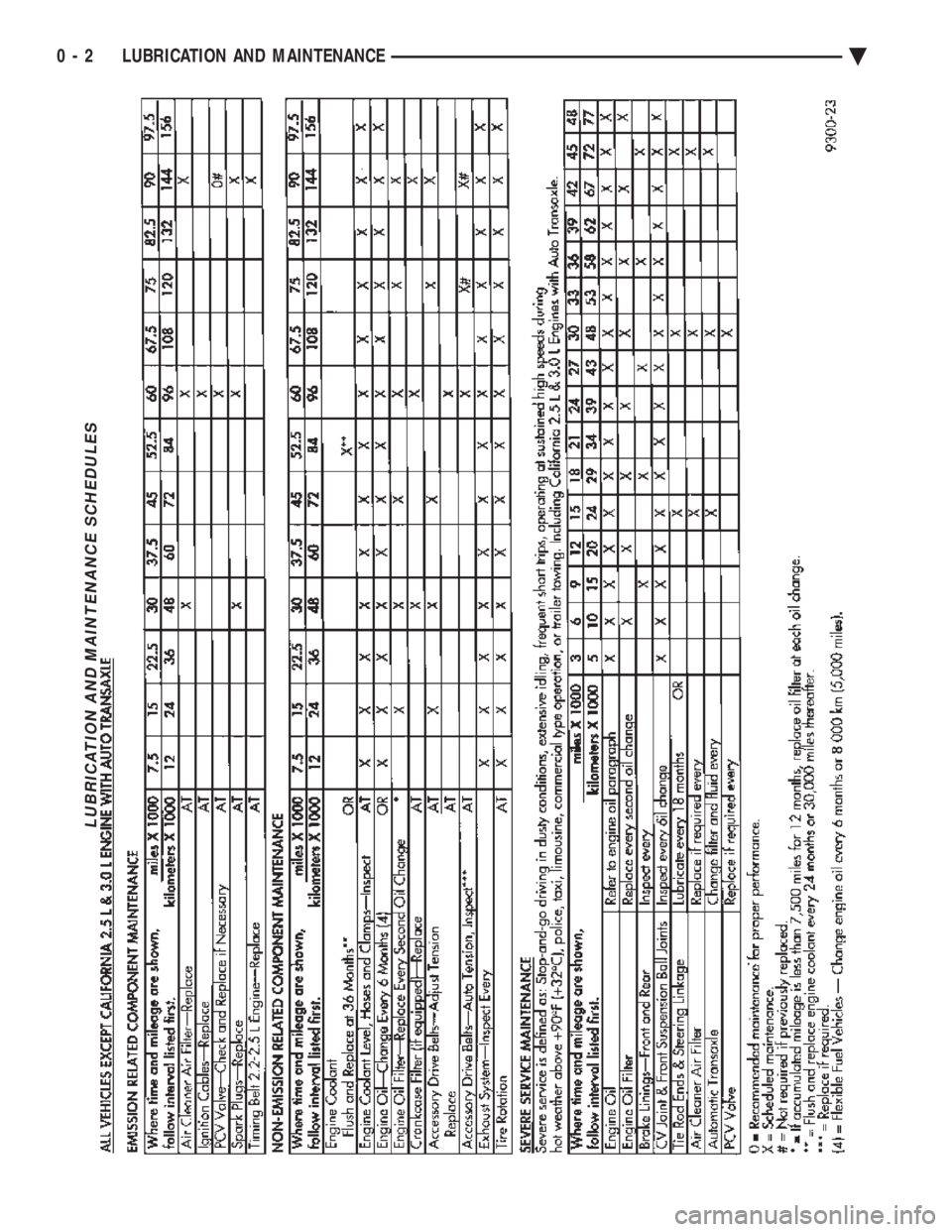
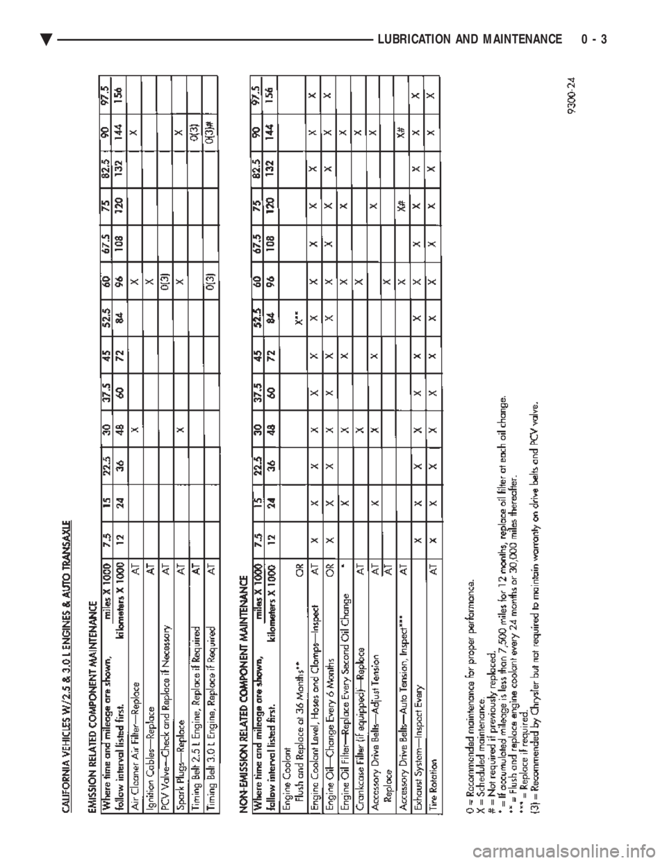
LUBRICATION AND MAINTENANCE SCHEDULES
0 - 2 LUBRICATION AND MAINTENANCEÄ
Page 39 of 2438

ÄLUBRICATION AND MAINTENANCE 0 - 3
Page 40 of 2438

LUBRICANTS AND GREASES
Lubricating grease is rated for quality and usage
by the NLGI. All approved products have the NLGI
symbol on the label. At the bottom NLGI symbol is the usage and qual-
ity identification letters. Wheel bearing lubricant is
identified by the letter ``G''. Chassis lubricant is iden-
tified by the letter ``L''. The letter following the us-
age letter indicates the quality of the lubricant. The
following symbols indicate the highest quality.
FLUID CAPACITIES
Fuel Tank
AP,AG and AJ ......................................53 L (14 gal.)
AA,AC and AY .....................................60 L (16 gal.)
AA-Flexible Fuel ..................................68 L (18 gal.)
Engine Oil
All.........................................................3.8 L (4.5 qts.)
Cooling System
2.2L ......................................................8.5 L (9.0 qts.)
2.5L ......................................................8.5 L (9.0 qts.)
3.0L ......................................................9.0 L (9.5 qts.)
3.3L ......................................................9.0 L (9.5 qts.)
3.8L ......................................................9.0 L (9.5 qts.)
Includes heater and coolant recovery bottle
Automatic Transaxle
Estimated Service Fill
ALL ......................................................3.8 L (4.0 qts.)
Overhaul Fill Capacity with Torque Converter
Empty
3-speed Fleet .......................................8.7 L (9.2 qts.)
3-speed .................................................8.2 L (8.8 qts.)
4-speed Electronic ................................9.4L (9.9 qts.)
Manual Transaxle
All ..........................................................9.4L (9.9 qts.)
Fill to bottom of fill hole.
Power Steering
All ...........................................................75L (1.5 pts.)
PARTS REQUIRING NO LUBRICATION
Many components on a Chrysler Corporation vehi-
cle require no periodic maintenance. Some compo-
nents are sealed and permanently lubricated. Rubber
bushings can deteriorate or limit damping ability if
lubricated. The following list of components require
no lubrication: ²
Air Pump
² Generator Bushings
² Drive Belts
² Drive Belt Idler/Tensioner Pulley
² Front Wheel Bearings
² Rubber Bushings
² Starter Bearings/Bushings
² Suspension Strut Bearings
² Throttle Control Cable
² Throttle Linkage
² Water Pump Bearings
JUMP STARTING PROCEDURE
WARNING: REVIEW ALL SAFETY PRECAUTIONS
AND WARNINGS IN GROUP 8A, BATTERY/START-
ING/CHARGING SYSTEMS DIAGNOSTICS. DO NOT JUMP START A FROZEN BATTERY, PER-
SONAL INJURY CAN RESULT. DO NOT JUMP START WHEN BATTERY INDICA-
TOR DOT IS YELLOW OR BRIGHT COLOR. DO NOT ALLOW JUMPER CABLE CLAMPS TO
TOUCH EACH OTHER WHEN CONNECTED TO A
BOOSTER SOURCE. DO NOT USE OPEN FLAME NEAR BATTERY.
REMOVE METALLIC JEWELRY WORN ON HANDS
OR WRISTS TO AVOID INJURY BY ACCIDENTAL
ARCHING OF BATTERY CURRENT. WHEN USING A HIGH OUTPUT BOOSTING DE-
VICE, DO NOT ALLOW BATTERY VOLTAGE TO EX-
CEED 16 VOLTS. REFER TO INSTRUCTIONS
PROVIDED WITH DEVICE BEING USED.
CAUTION: When using another vehicle as a
booster, do not allow vehicles to touch. Electrical
systems can be damaged on either vehicle.
TO JUMP START A DISABLED VEHICLE:
(1) Raise hood on disabled vehicle and visually in-
spect engine compartment for:
² Battery cable clamp condition, clean if necessary.
² Frozen battery.
² Yellow or bright color test indicator, if equipped.
² Low battery fluid level.
² Generator drive belt condition and tension.
² Fuel fumes or leakage, correct if necessary.
CAUTION: If the cause of starting problem on dis-
abled vehicle is severe, damage to booster vehicle
charging system can result.
(2) When using another vehicle as a booster
source, turn off all accessories, place gear selector in
park or neutral, set park brake and operate engine
at 1200 rpm.
NLGI SYMBOL
0 - 4 LUBRICATION AND MAINTENANCE Ä
Page 41 of 2438

(3) On disabled vehicle, place gear selector in park
or neutral and set park brake. Turn off all accesso-
ries. (4) Connect jumper cables to booster battery. RED
clamp to positive terminal (+). BLACK clamp to
negative terminal (-). DO NOT allow clamps at oppo-
site end of cables to touch, electrical arc will result
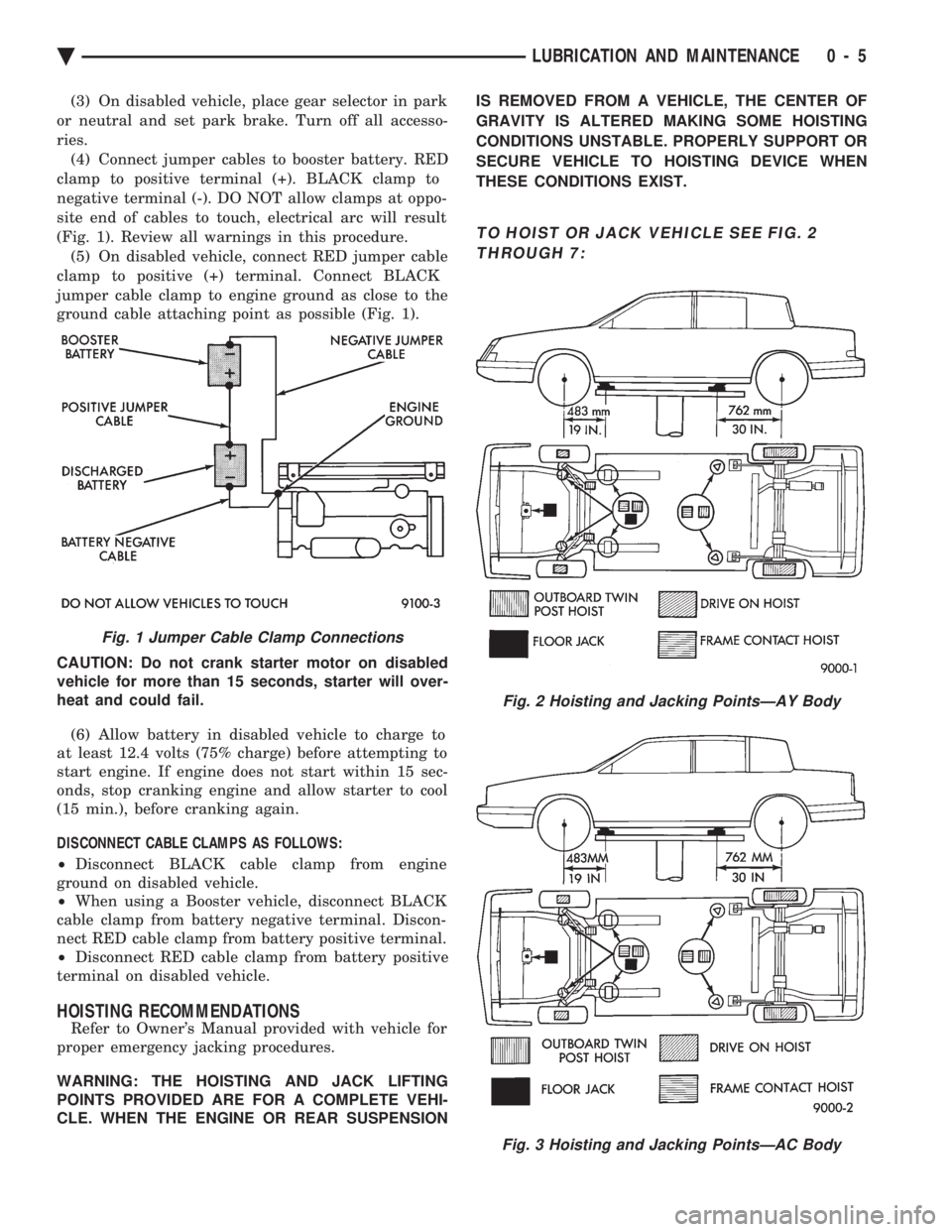
(Fig. 1). Review all warnings in this procedure. (5) On disabled vehicle, connect RED jumper cable
clamp to positive (+) terminal. Connect BLACK
jumper cable clamp to engine ground as close to the
ground cable attaching point as possible (Fig. 1).
CAUTION: Do not crank starter motor on disabled
vehicle for more than 15 seconds, starter will over-
heat and could fail.
(6) Allow battery in disabled vehicle to charge to
at least 12.4 volts (75% charge) before attempting to
start engine. If engine does not start within 15 sec-
onds, stop cranking engine and allow starter to cool
(15 min.), before cranking again.
DISCONNECT CABLE CLAMPS AS FOLLOWS:
² Disconnect BLACK cable clamp from engine
ground on disabled vehicle.
² When using a Booster vehicle, disconnect BLACK
cable clamp from battery negative terminal. Discon-
nect RED cable clamp from battery positive terminal.
² Disconnect RED cable clamp from battery positive
terminal on disabled vehicle.
HOISTING RECOMMENDATIONS
Refer to Owner's Manual provided with vehicle for
proper emergency jacking procedures.
WARNING: THE HOISTING AND JACK LIFTING
POINTS PROVIDED ARE FOR A COMPLETE VEHI-
CLE. WHEN THE ENGINE OR REAR SUSPENSION IS REMOVED FROM A VEHICLE, THE CENTER OF
GRAVITY IS ALTERED MAKING SOME HOISTING
CONDITIONS UNSTABLE. PROPERLY SUPPORT OR
SECURE VEHICLE TO HOISTING DEVICE WHEN
THESE CONDITIONS EXIST.
TO HOIST OR JACK VEHICLE SEE FIG. 2 THROUGH 7:
Fig. 1 Jumper Cable Clamp Connections
Fig. 2 Hoisting and Jacking PointsÐAY Body
Fig. 3 Hoisting and Jacking PointsÐAC Body
Ä LUBRICATION AND MAINTENANCE 0 - 5
Page 42 of 2438

Fig. 4 Hoisting and Jacking PointsÐAA Body
Fig. 5 Hoisting and Jacking PointsÐAG Body
Fig. 6 Hoisting and Jacking PointsÐAJ Body
Fig. 7 Hoisting and Jacking PointsÐAP Body
0 - 6 LUBRICATION AND MAINTENANCE Ä