1993 CHEVROLET DYNASTY maintenance
[x] Cancel search: maintenancePage 220 of 2438
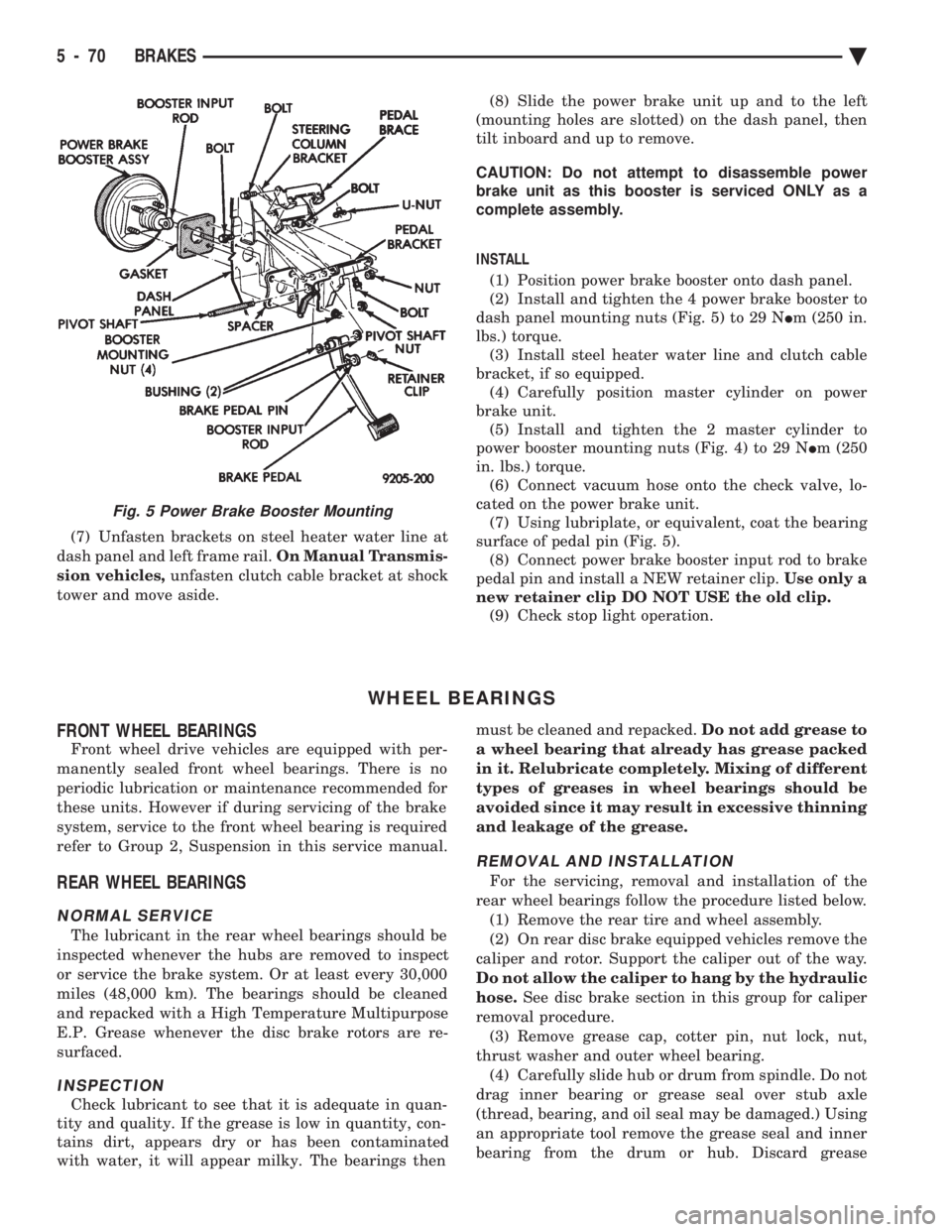
(7) Unfasten brackets on steel heater water line at
dash panel and left frame rail. On Manual Transmis-
sion vehicles, unfasten clutch cable bracket at shock
tower and move aside. (8) Slide the power brake unit up and to the left
(mounting holes are slotted) on the dash panel, then
tilt inboard and up to remove.
CAUTION: Do not attempt to disassemble power
brake unit as this booster is serviced ONLY as a
complete assembly.
INSTALL (1) Position power brake booster onto dash panel.
(2) Install and tighten the 4 power brake booster to
dash panel mounting nuts (Fig. 5) to 29 N Im (250 in.
lbs.) torque. (3) Install steel heater water line and clutch cable
bracket, if so equipped. (4) Carefully position master cylinder on power
brake unit. (5) Install and tighten the 2 master cylinder to
power booster mounting nuts (Fig. 4) to 29 N Im (250
in. lbs.) torque. (6) Connect vacuum hose onto the check valve, lo-
cated on the power brake unit. (7) Using lubriplate, or equivalent, coat the bearing
surface of pedal pin (Fig. 5). (8) Connect power brake booster input rod to brake
pedal pin and install a NEW retainer clip. Use only a
new retainer clip DO NOT USE the old clip. (9) Check stop light operation.
WHEEL BEARINGS
FRONT WHEEL BEARINGS
Front wheel drive vehicles are equipped with per-
manently sealed front wheel bearings. There is no
periodic lubrication or maintenance recommended for
these units. However if during servicing of the brake
system, service to the front wheel bearing is required
refer to Group 2, Suspension in this service manual.
REAR WHEEL BEARINGS
NORMAL SERVICE
The lubricant in the rear wheel bearings should be
inspected whenever the hubs are removed to inspect
or service the brake system. Or at least every 30,000
miles (48,000 km). The bearings should be cleaned
and repacked with a High Temperature Multipurpose
E.P. Grease whenever the disc brake rotors are re-
surfaced.
INSPECTION
Check lubricant to see that it is adequate in quan-
tity and quality. If the grease is low in quantity, con-
tains dirt, appears dry or has been contaminated
with water, it will appear milky. The bearings then must be cleaned and repacked.
Do not add grease to
a wheel bearing that already has grease packed
in it. Relubricate completely. Mixing of different
types of greases in wheel bearings should be
avoided since it may result in excessive thinning
and leakage of the grease.
REMOVAL AND INSTALLATION
For the servicing, removal and installation of the
rear wheel bearings follow the procedure listed below. (1) Remove the rear tire and wheel assembly.
(2) On rear disc brake equipped vehicles remove the
caliper and rotor. Support the caliper out of the way.
Do not allow the caliper to hang by the hydraulic
hose. See disc brake section in this group for caliper
removal procedure. (3) Remove grease cap, cotter pin, nut lock, nut,
thrust washer and outer wheel bearing. (4) Carefully slide hub or drum from spindle. Do not
drag inner bearing or grease seal over stub axle
(thread, bearing, and oil seal may be damaged.) Using
an appropriate tool remove the grease seal and inner
bearing from the drum or hub. Discard grease
Fig. 5 Power Brake Booster Mounting
5 - 70 BRAKES Ä
Page 260 of 2438
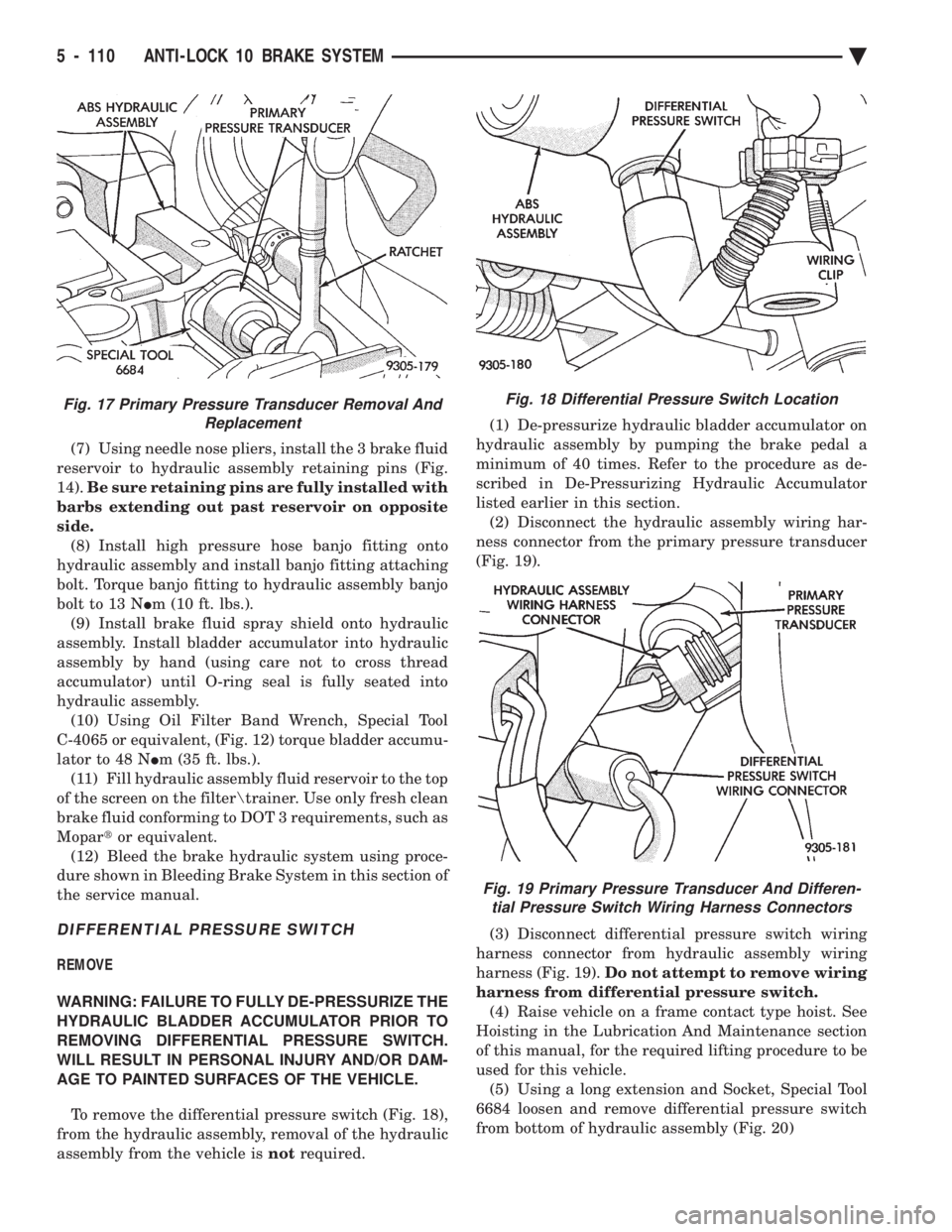
(7) Using needle nose pliers, install the 3 brake fluid
reservoir to hydraulic assembly retaining pins (Fig.
14). Be sure retaining pins are fully installed with
barbs extending out past reservoir on opposite
side. (8) Install high pressure hose banjo fitting onto
hydraulic assembly and install banjo fitting attaching
bolt. Torque banjo fitting to hydraulic assembly banjo
bolt to 13 N Im (10 ft. lbs.).
(9) Install brake fluid spray shield onto hydraulic
assembly. Install bladder accumulator into hydraulic
assembly by hand (using care not to cross thread
accumulator) until O-ring seal is fully seated into
hydraulic assembly. (10) Using Oil Filter Band Wrench, Special Tool
C-4065 or equivalent, (Fig. 12) torque bladder accumu-
lator to 48 N Im (35 ft. lbs.).
(11) Fill hydraulic assembly fluid reservoir to the top
of the screen on the filter rainer. Use only fresh clean
brake fluid conforming to DOT 3 requirements, such as
Mopar tor equivalent.
(12) Bleed the brake hydraulic system using proce-
dure shown in Bleeding Brake System in this section of
the service manual.
DIFFERENTIAL PRESSURE SWITCH
REMOVE
WARNING: FAILURE TO FULLY DE-PRESSURIZE THE
HYDRAULIC BLADDER ACCUMULATOR PRIOR TO
REMOVING DIFFERENTIAL PRESSURE SWITCH.
WILL RESULT IN PERSONAL INJURY AND/OR DAM-
AGE TO PAINTED SURFACES OF THE VEHICLE.
To remove the differential pressure switch (Fig. 18),
from the hydraulic assembly, removal of the hydraulic
assembly from the vehicle is notrequired. (1) De-pressurize hydraulic bladder accumulator on
hydraulic assembly by pumping the brake pedal a
minimum of 40 times. Refer to the procedure as de-
scribed in De-Pressurizing Hydraulic Accumulator
listed earlier in this section. (2) Disconnect the hydraulic assembly wiring har-
ness connector from the primary pressure transducer
(Fig. 19).
(3) Disconnect differential pressure switch wiring
harness connector from hydraulic assembly wiring
harness (Fig. 19). Do not attempt to remove wiring
harness from differential pressure switch. (4) Raise vehicle on a frame contact type hoist. See
Hoisting in the Lubrication And Maintenance section
of this manual, for the required lifting procedure to be
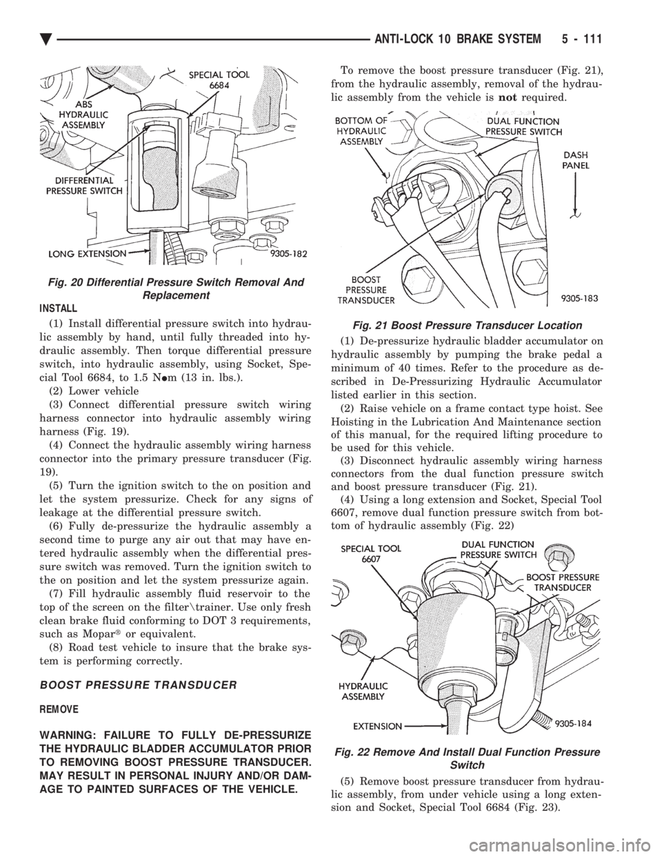
used for this vehicle. (5) Using a long extension and Socket, Special Tool
6684 loosen and remove differential pressure switch
from bottom of hydraulic assembly (Fig. 20)
Fig. 18 Differential Pressure Switch Location
Fig. 19 Primary Pressure Transducer And Differen- tial Pressure Switch Wiring Harness Connectors
Fig. 17 Primary Pressure Transducer Removal And Replacement
5 - 110 ANTI-LOCK 10 BRAKE SYSTEM Ä
Page 261 of 2438
INSTALL (1) Install differential pressure switch into hydrau-
lic assembly by hand, until fully threaded into hy-
draulic assembly. Then torque differential pressure
switch, into hydraulic assembly, using Socket, Spe-
cial Tool 6684, to 1.5 N Im (13 in. lbs.).
(2) Lower vehicle
(3) Connect differential pressure switch wiring
harness connector into hydraulic assembly wiring
harness (Fig. 19). (4) Connect the hydraulic assembly wiring harness
connector into the primary pressure transducer (Fig.
19). (5) Turn the ignition switch to the on position and
let the system pressurize. Check for any signs of
leakage at the differential pressure switch. (6) Fully de-pressurize the hydraulic assembly a
second time to purge any air out that may have en-
tered hydraulic assembly when the differential pres-
sure switch was removed. Turn the ignition switch to
the on position and let the system pressurize again. (7) Fill hydraulic assembly fluid reservoir to the
top of the screen on the filter rainer. Use only fresh
clean brake fluid conforming to DOT 3 requirements,
such as Mopar tor equivalent.
(8) Road test vehicle to insure that the brake sys-
tem is performing correctly.
BOOST PRESSURE TRANSDUCER
REMOVE
WARNING: FAILURE TO FULLY DE-PRESSURIZE
THE HYDRAULIC BLADDER ACCUMULATOR PRIOR
TO REMOVING BOOST PRESSURE TRANSDUCER.
MAY RESULT IN PERSONAL INJURY AND/OR DAM-
AGE TO PAINTED SURFACES OF THE VEHICLE. To remove the boost pressure transducer (Fig. 21),
from the hydraulic assembly, removal of the hydrau-
lic assembly from the vehicle is notrequired.
(1) De-pressurize hydraulic bladder accumulator on
hydraulic assembly by pumping the brake pedal a
minimum of 40 times. Refer to the procedure as de-
scribed in De-Pressurizing Hydraulic Accumulator
listed earlier in this section. (2) Raise vehicle on a frame contact type hoist. See
Hoisting in the Lubrication And Maintenance section
of this manual, for the required lifting procedure to
be used for this vehicle. (3) Disconnect hydraulic assembly wiring harness
connectors from the dual function pressure switch
and boost pressure transducer (Fig. 21). (4) Using a long extension and Socket, Special Tool
6607, remove dual function pressure switch from bot-
tom of hydraulic assembly (Fig. 22)
(5) Remove boost pressure transducer from hydrau-
lic assembly, from under vehicle using a long exten-
sion and Socket, Special Tool 6684 (Fig. 23).
Fig. 20 Differential Pressure Switch Removal And Replacement
Fig. 21 Boost Pressure Transducer Location
Fig. 22 Remove And Install Dual Function Pressure Switch
Ä ANTI-LOCK 10 BRAKE SYSTEM 5 - 111
Page 316 of 2438
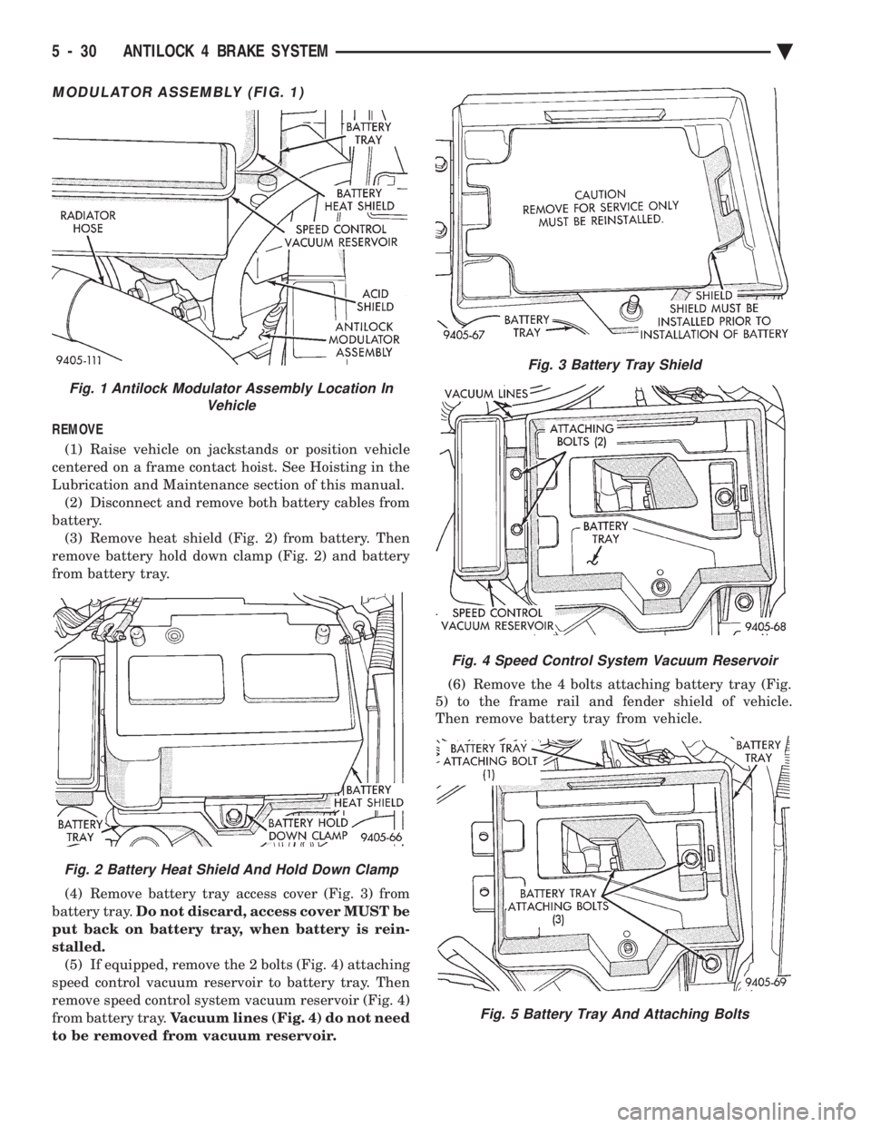
MODULATOR ASSEMBLY (FIG. 1)
REMOVE (1) Raise vehicle on jackstands or position vehicle
centered on a frame contact hoist. See Hoisting in the
Lubrication and Maintenance section of this manual. (2) Disconnect and remove both battery cables from
battery. (3) Remove heat shield (Fig. 2) from battery. Then
remove battery hold down clamp (Fig. 2) and battery
from battery tray.
(4) Remove battery tray access cover (Fig. 3) from
battery tray. Do not discard, access cover MUST be
put back on battery tray, when battery is rein-
stalled. (5) If equipped, remove the 2 bolts (Fig. 4) attaching
speed control vacuum reservoir to battery tray. Then
remove speed control system vacuum reservoir (Fig. 4)
from battery tray. Vacuum lines (Fig. 4) do not need
to be removed from vacuum reservoir. (6) Remove the 4 bolts attaching battery tray (Fig.
5) to the frame rail and fender shield of vehicle.
Then remove battery tray from vehicle.
Fig. 3 Battery Tray Shield
Fig. 4 Speed Control System Vacuum Reservoir
Fig. 5 Battery Tray And Attaching Bolts
Fig. 1 Antilock Modulator Assembly Location In Vehicle
Fig. 2 Battery Heat Shield And Hold Down Clamp
5 - 30 ANTILOCK 4 BRAKE SYSTEM Ä
Page 357 of 2438

-37ÉC (-35ÉF) to -59ÉC (-50ÉF). If it looses color or
becomes contaminated, drain, flush, and replace with
fresh properly mixed solution.
SERVICE
Coolant should be changed at 52,500 miles or three
years, whichever occurs first, then every two years or
30,000 miles.
ROUTINE LEVEL CHECK
Do not remove radiator cap for routine coolant
level inspections. The coolant reserve system provides a quick visual
method for determining the coolant level without re-
moving the radiator cap. Simply observe, with the
engine idling and warmed up to normal operating
temperature, that the level of the coolant in the reserve
tank (Figs. 5 and 6) is between the minimum and
maximum marks.
ADDING ADDITIONAL COOLANT
The radiator cap should not be removed. When
additional coolant is needed to maintain this level, it
should be added to the coolant reserve tank. Use only
50/50 concentration of ethylene glycol type antifreeze
and water.
SERVICE COOLANT LEVEL
The cooling system is closed and designed to main-
tain coolant level to the top of the radiator. When servicing requires a coolant level check in the
radiator, the engine must be offand notunder pres-
sure. Drain several ounces of coolant from the radiator
drain cock while observing the Coolant Recovery Sys-
tem (CRS) Tank. Coolant level in the CRS tank should
drop slightly. Then remove the radiator cap. The radia-
tor should be full to the top. If not, and the coolant level
in the CRS tank is at the MIN mark there is a air leak
in the CRS system. Check hose or hose connections to
the CRS tank, radiator filler neck or the pressure cap
seal to the radiator filler neck for leaks.
LOW COOLANT LEVEL AERATION
Low coolant level in a cross flow radiator will equal-
ize in both tanks with engine off. With engine at
running operating temperature the high pressure inlet
tank runs full and the low pressure outlet tank drops.
If this level drops below the top of the transmission oil
cooler, air will be sucked into the water pump:
² Transmission oil will become hotter.
² High reading shown on the temperature gauge.
² Air in the coolant will also cause loss of flow through
the heater.
² Exhaust gas leaks into the coolant can also cause the
same problems.
DEAERATION
Air can only be removed from the system by gather-
ing under the pressure cap. On the next heat up it will
be pushed past the pressure cap into the CRS tank by
thermal expansion of the coolant. It then escapes to the
atmosphere in the CRS tank and is replaced with solid
coolant on cool down.
COOLING SYSTEM DRAIN, CLEAN, FLUSH AND
REFILL
Drain, flush, and fill the cooling system at the
mileage or time intervals specified in the Maintenance
Schedule in this Group. If the solution is dirty or rusty
or contains a considerable amount of sediment, clean
and flush with a reliable cooling system cleaner. Care
should be taken in disposing of the used engine coolant
from your vehicle. Check governmental regulations for
disposal of used engine coolant.
DRAINING
To drain cooling system move temperature selector
for heater to full heat with engine running (to provide
vacuum for actuation). Without removing radiator
pressure cap and with system not under pres-
sure, Shut engine off and open draincock. The coolant
reserve tank (Fig. 5) should empty first, then remove
radiator pressure cap. (if not, see Testing Cooling
System for leaks). To vent 2.2/2.5L engines remove the
plug above thermostat housing (Fig. 1). For Turbo III
engines remove coolant temperature sensor in the
thermostat housing (Fig. 2). For 3.3L /3.8L engine
remove the engine temperature sending unit (Fig. 3).
Removal of a plug or other component is required
because the thermostat has no air vent and prevents
air flow through it. This allows the coolant to drain
from the engine block.
Fig. 1 Thermostat Housing Drain/Fill PlugÐ2.2/2.5L Engines
Ä COOLING SYSTEM 7 - 15
Page 375 of 2438
BATTERY TEST PROCEDURES ON-VEHICLE INDEX
page page
Battery Charging .......................... 7
Battery Load Test ......................... 6
Battery Open Circuit Voltage Test ............. 4
Causes of Battery Discharging ............... 4 General Information
........................ 3
State of Charge Tests ...................... 4
Test Indicator ............................ 3
GENERAL INFORMATION
The battery stores, stabilizes, and produces electri-
cal current to operate various electrical systems in
the vehicle. The determination of whether a battery
is good or bad is made by the battery's ability to ac-
cept a charge. It also must produce high amperage
current output over an extended period to be able to
start the vehicle. The capability of the battery to
store electrical current comes from a chemical reac-
tion. This reaction takes place between the sulfuric
acid solution electrolyte and the lead +/- plates in
each cell of the battery. As the battery discharges,
the plates react with the acid from the electrolyte.
When the charging system charges the battery, the
water is converted to sulfuric acid in the battery. The
amount of acid, specific gravity in the electrolyte can
be measured with a hydrometer. The factory in-
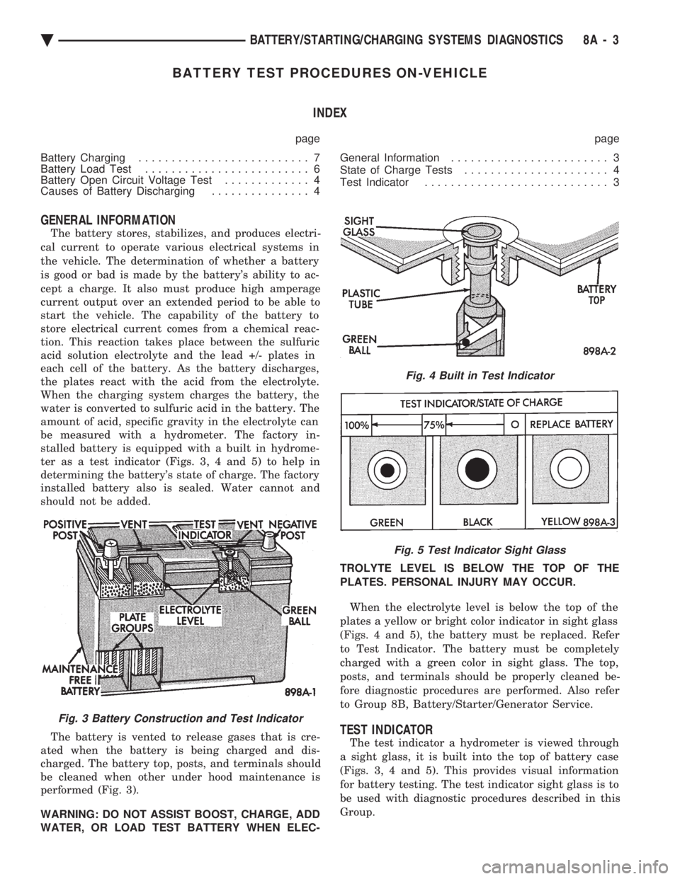
stalled battery is equipped with a built in hydrome-
ter as a test indicator (Figs. 3, 4 and 5) to help in
determining the battery's state of charge. The factory
installed battery also is sealed. Water cannot and
should not be added.
The battery is vented to release gases that is cre-
ated when the battery is being charged and dis-
charged. The battery top, posts, and terminals should
be cleaned when other under hood maintenance is
performed (Fig. 3).
WARNING: DO NOT ASSIST BOOST, CHARGE, ADD
WATER, OR LOAD TEST BATTERY WHEN ELEC- TROLYTE LEVEL IS BELOW THE TOP OF THE
PLATES. PERSONAL INJURY MAY OCCUR.
When the electrolyte level is below the top of the
plates a yellow or bright color indicator in sight glass
(Figs. 4 and 5), the battery must be replaced. Refer
to Test Indicator. The battery must be completely
charged with a green color in sight glass. The top,
posts, and terminals should be properly cleaned be-
fore diagnostic procedures are performed. Also refer
to Group 8B, Battery/Starter/Generator Service.
TEST INDICATOR
The test indicator a hydrometer is viewed through
a sight glass, it is built into the top of battery case
(Figs. 3, 4 and 5). This provides visual information
for battery testing. The test indicator sight glass is to
be used with diagnostic procedures described in this
Group.
Fig. 3 Battery Construction and Test Indicator
Fig. 4 Built in Test Indicator
Fig. 5 Test Indicator Sight Glass
Ä BATTERY/STARTING/CHARGING SYSTEMS DIAGNOSTICS 8A - 3
Page 376 of 2438

It is important when using the Test Indicator that
the battery be level and have a clean top to see the
correct indications. A light may be required to view
the Indicator.
WARNING: DO NOT USE OPEN FLAME NEAR BAT-
TERY BECAUSE OF EXPLOSIVE GASES AT FORM
ABOVE BATTERY.
STATE OF CHARGE TESTS
USING TEST INDICATOR
The built in test hydrometer (Figs. 3, 4 and 5) mea-
sures the specific gravity of the electrolyte. Specific
Gravity (SG) of the electrolyte will show state of
charge voltage. The test indicator WILL NOT show
cranking capacity of the battery. Refer to Battery
Load. Look into the sight glass (Figs. 4 and 5) and
note the color of the indicator (Fig. 5). Refer to the
following description of colors:
² GREEN = 75 to 100 degree state of charge
The battery is adequately charged for further test-
ing and may be returned to use. If the vehicle will
not crank for a maximum 15 seconds, refer to Bat-
tery Load Test in this Group for more information.
² BLACK OR DAR K=0to75degree state of
charge The battery is INADEQUATELY charged and
must be charged until green dot is visible, (12.4 volts
or greater) before the battery is tested or returned to
use. Refer to Causes of Battery Discharging.
² YELLOW OR BRIGHT COLOR = Battery must
be replace
WARNING: DO NOT CHARGE, ASSIST BOOST,
LOAD TEST, OR ADD WATER TO THE BATTERY
WHEN YELLOW OR BRIGHT COLOR DOT IS VISI-
BLE. PERSONAL INJURY MAY OCCUR.
A yellow or bright color dot shows electrolyte level
in battery is below the test indicator (Fig. 5). Water
cannot be added to a maintenance free battery. The
battery must be replaced. A low electrolyte level may
be caused by an over charging condition. Refer to
Generator Test Procedures on Vehicle.
CAUSES OF BATTERY DISCHARGING
It is normal to have a small 5 to 30 milliamperes
continuous electrical draw from the battery. This
draw will take place with the ignition in the OFF po-
sition, and the courtesy, dome, storage compart-
ments, and engine compartment lights OFF. The
continuous draw is due to various electronic features
or accessories that require electrical current with the
ignition OFF to function properly. When a vehicle is
not used over an extended period approximately 20
days the Main Fusible Link Connector (Fig. 6)
should be disconnected. This is located near the bat- tery on the engine wiring harness. Disconnection of
this connector will help prevent battery discharging.
Refer to Fig. 7 for Battery Diagnostics.
ABNORMAL BATTERY DISCHARGING
(1) Corroded battery posts, cables or terminals.
(2) Loose or worn generator drive belt.
(3) Electrical loads that exceed the output of the
charging system due to equipment or accessories in-
stalled after delivery. (4) Slow driving speeds in heavy traffic conditions
or prolonged idling with high-amperage electrical
systems in use. (5) Defective electrical circuit or component caus-
ing excess Ignition Off Draw (IOD). Refer to Ignition
OFF Draw (IOD). (6) Defective charging system.
(7) Defective battery.
BATTERY OPEN CIRCUIT VOLTAGE TEST
An open circuit voltage, no load test will show the
state of charge in a battery. Also, if it will pass a
load test of 50 percent of the battery cold crank rat-
ing. Refer to Battery Load Test. If a battery has an
open circuit voltage reading of 12.4 volts or greater,
and will not pass a load test, it is defective and re-
placement would be required. To test open circuit
voltage, perform the following operation: (1) Remove both battery cables, negative first. If
the battery has been boosted, charged, or loaded just
prior to this operation, allow the battery a few min-
utes to stabilize. (2) Using a voltmeter connected to the battery
posts and measure the open circuit voltage (Fig. 8).
Fig. 6 Main Fusible Link Connector
8A - 4 BATTERY/STARTING/CHARGING SYSTEMS DIAGNOSTICS Ä
Page 403 of 2438
BATTERY/STARTER/GENERATOR SERVICE
CONTENTS
page page
BATTERY REMOVAL, INSTALLATION AND SERVICE ............................. 1
GENERATOR ............................ 9 SPECIFICATIONS
....................... 12
STARTER ............................... 4
BATTERY REMOVAL, INSTALLATION AND SERVICE
GENERAL INFORMATION
This first section will cover Battery replacement and
service procedures only. For Battery diagnostic proce-
dures, refer to Group 8A, Battery/Starting/Charging
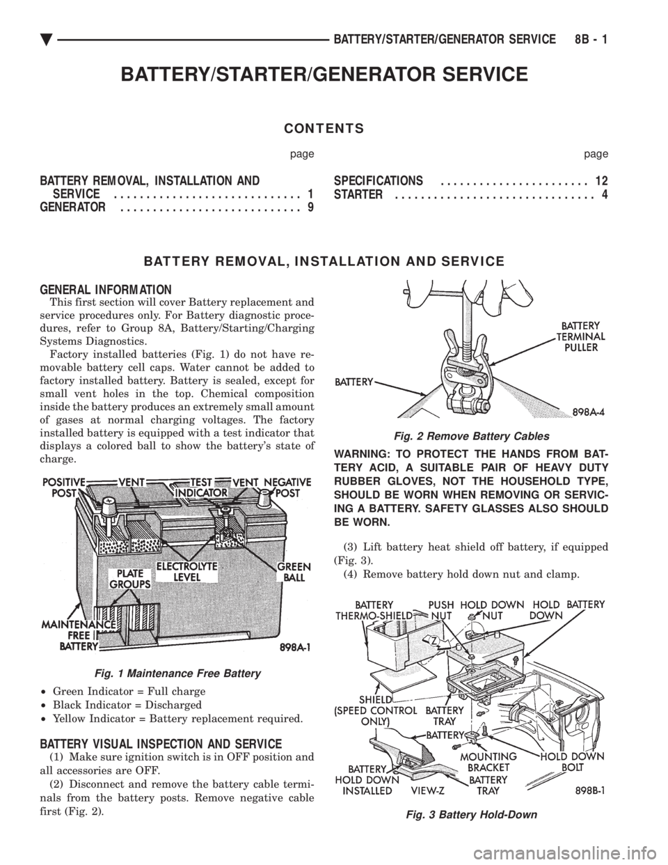
Systems Diagnostics. Factory installed batteries (Fig. 1) do not have re-
movable battery cell caps. Water cannot be added to
factory installed battery. Battery is sealed, except for
small vent holes in the top. Chemical composition
inside the battery produces an extremely small amount
of gases at normal charging voltages. The factory
installed battery is equipped with a test indicator that
displays a colored ball to show the battery's state of
charge.
² Green Indicator = Full charge
² Black Indicator = Discharged
² Yellow Indicator = Battery replacement required.
BATTERY VISUAL INSPECTION AND SERVICE
(1) Make sure ignition switch is in OFF position and
all accessories are OFF. (2) Disconnect and remove the battery cable termi-
nals from the battery posts. Remove negative cable
first (Fig. 2). WARNING: TO PROTECT THE HANDS FROM BAT-
TERY ACID, A SUITABLE PAIR OF HEAVY DUTY
RUBBER GLOVES, NOT THE HOUSEHOLD TYPE,
SHOULD BE WORN WHEN REMOVING OR SERVIC-
ING A BATTERY. SAFETY GLASSES ALSO SHOULD
BE WORN.
(3) Lift battery heat shield off battery, if equipped
(Fig. 3). (4) Remove battery hold down nut and clamp.
Fig. 1 Maintenance Free Battery
Fig. 2 Remove Battery Cables
Fig. 3 Battery Hold-Down
Ä BATTERY/STARTER/GENERATOR SERVICE 8B - 1