1993 CHEVROLET DYNASTY open gas tank
[x] Cancel search: open gas tankPage 357 of 2438

-37ÉC (-35ÉF) to -59ÉC (-50ÉF). If it looses color or
becomes contaminated, drain, flush, and replace with
fresh properly mixed solution.
SERVICE
Coolant should be changed at 52,500 miles or three
years, whichever occurs first, then every two years or
30,000 miles.
ROUTINE LEVEL CHECK
Do not remove radiator cap for routine coolant
level inspections. The coolant reserve system provides a quick visual
method for determining the coolant level without re-
moving the radiator cap. Simply observe, with the
engine idling and warmed up to normal operating
temperature, that the level of the coolant in the reserve
tank (Figs. 5 and 6) is between the minimum and
maximum marks.
ADDING ADDITIONAL COOLANT
The radiator cap should not be removed. When
additional coolant is needed to maintain this level, it
should be added to the coolant reserve tank. Use only
50/50 concentration of ethylene glycol type antifreeze
and water.
SERVICE COOLANT LEVEL
The cooling system is closed and designed to main-
tain coolant level to the top of the radiator. When servicing requires a coolant level check in the
radiator, the engine must be offand notunder pres-
sure. Drain several ounces of coolant from the radiator
drain cock while observing the Coolant Recovery Sys-
tem (CRS) Tank. Coolant level in the CRS tank should
drop slightly. Then remove the radiator cap. The radia-
tor should be full to the top. If not, and the coolant level
in the CRS tank is at the MIN mark there is a air leak
in the CRS system. Check hose or hose connections to
the CRS tank, radiator filler neck or the pressure cap
seal to the radiator filler neck for leaks.
LOW COOLANT LEVEL AERATION
Low coolant level in a cross flow radiator will equal-
ize in both tanks with engine off. With engine at
running operating temperature the high pressure inlet
tank runs full and the low pressure outlet tank drops.
If this level drops below the top of the transmission oil
cooler, air will be sucked into the water pump:
² Transmission oil will become hotter.
² High reading shown on the temperature gauge.
² Air in the coolant will also cause loss of flow through
the heater.
² Exhaust gas leaks into the coolant can also cause the
same problems.
DEAERATION
Air can only be removed from the system by gather-
ing under the pressure cap. On the next heat up it will
be pushed past the pressure cap into the CRS tank by
thermal expansion of the coolant. It then escapes to the
atmosphere in the CRS tank and is replaced with solid
coolant on cool down.
COOLING SYSTEM DRAIN, CLEAN, FLUSH AND
REFILL
Drain, flush, and fill the cooling system at the
mileage or time intervals specified in the Maintenance
Schedule in this Group. If the solution is dirty or rusty
or contains a considerable amount of sediment, clean
and flush with a reliable cooling system cleaner. Care
should be taken in disposing of the used engine coolant
from your vehicle. Check governmental regulations for
disposal of used engine coolant.
DRAINING
To drain cooling system move temperature selector
for heater to full heat with engine running (to provide
vacuum for actuation). Without removing radiator
pressure cap and with system not under pres-
sure, Shut engine off and open draincock. The coolant
reserve tank (Fig. 5) should empty first, then remove
radiator pressure cap. (if not, see Testing Cooling
System for leaks). To vent 2.2/2.5L engines remove the
plug above thermostat housing (Fig. 1). For Turbo III
engines remove coolant temperature sensor in the
thermostat housing (Fig. 2). For 3.3L /3.8L engine
remove the engine temperature sending unit (Fig. 3).
Removal of a plug or other component is required
because the thermostat has no air vent and prevents
air flow through it. This allows the coolant to drain
from the engine block.
Fig. 1 Thermostat Housing Drain/Fill PlugÐ2.2/2.5L Engines
Ä COOLING SYSTEM 7 - 15
Page 359 of 2438
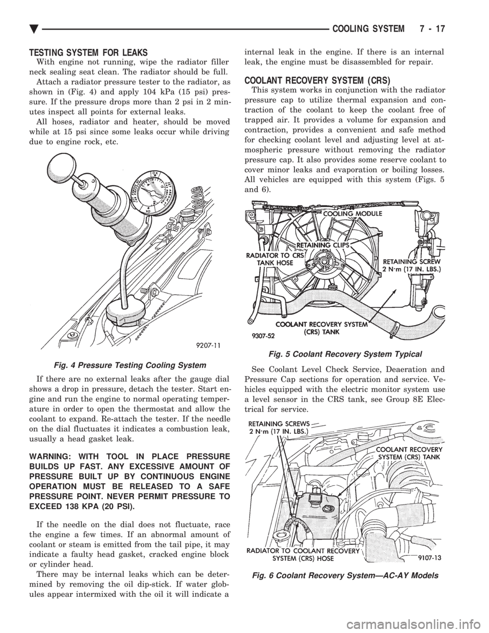
TESTING SYSTEM FOR LEAKS
With engine not running, wipe the radiator filler
neck sealing seat clean. The radiator should be full. Attach a radiator pressure tester to the radiator, as
shown in (Fig. 4) and apply 104 kPa (15 psi) pres-
sure. If the pressure drops more than 2 psi in 2 min-
utes inspect all points for external leaks. All hoses, radiator and heater, should be moved
while at 15 psi since some leaks occur while driving
due to engine rock, etc.
If there are no external leaks after the gauge dial
shows a drop in pressure, detach the tester. Start en-
gine and run the engine to normal operating temper-
ature in order to open the thermostat and allow the
coolant to expand. Re-attach the tester. If the needle
on the dial fluctuates it indicates a combustion leak,
usually a head gasket leak.
WARNING: WITH TOOL IN PLACE PRESSURE
BUILDS UP FAST. ANY EXCESSIVE AMOUNT OF
PRESSURE BUILT UP BY CONTINUOUS ENGINE
OPERATION MUST BE RELEASED TO A SAFE
PRESSURE POINT. NEVER PERMIT PRESSURE TO
EXCEED 138 KPA (20 PSI).
If the needle on the dial does not fluctuate, race
the engine a few times. If an abnormal amount of
coolant or steam is emitted from the tail pipe, it may
indicate a faulty head gasket, cracked engine block
or cylinder head. There may be internal leaks which can be deter-
mined by removing the oil dip-stick. If water glob-
ules appear intermixed with the oil it will indicate a internal leak in the engine. If there is an internal
leak, the engine must be disassembled for repair.
COOLANT RECOVERY SYSTEM (CRS)
This system works in conjunction with the radiator
pressure cap to utilize thermal expansion and con-
traction of the coolant to keep the coolant free of
trapped air. It provides a volume for expansion and
contraction, provides a convenient and safe method
for checking coolant level and adjusting level at at-
mospheric pressure without removing the radiator
pressure cap. It also provides some reserve coolant to
cover minor leaks and evaporation or boiling losses.
All vehicles are equipped with this system (Figs. 5
and 6).
See Coolant Level Check Service, Deaeration and
Pressure Cap sections for operation and service. Ve-
hicles equipped with the electric monitor system use
a level sensor in the CRS tank, see Group 8E Elec-
trical for service.
Fig. 4 Pressure Testing Cooling System
Fig. 5 Coolant Recovery System Typical
Fig. 6 Coolant Recovery SystemÐAC-AY Models
Ä COOLING SYSTEM 7 - 17
Page 360 of 2438
RADIATOR PRESSURE CAP
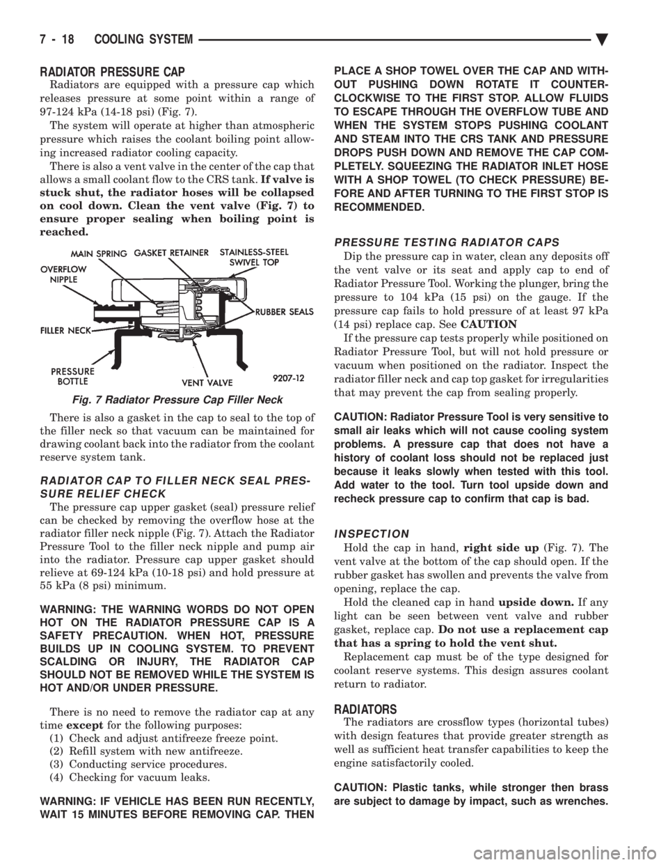
Radiators are equipped with a pressure cap which
releases pressure at some point within a range of
97-124 kPa (14-18 psi) (Fig. 7). The system will operate at higher than atmospheric
pressure which raises the coolant boiling point allow-
ing increased radiator cooling capacity. There is also a vent valve in the center of the cap that
allows a small coolant flow to the CRS tank. If valve is
stuck shut, the radiator hoses will be collapsed
on cool down. Clean the vent valve (Fig. 7) to
ensure proper sealing when boiling point is
reached.
There is also a gasket in the cap to seal to the top of
the filler neck so that vacuum can be maintained for
drawing coolant back into the radiator from the coolant
reserve system tank.
RADIATOR CAP TO FILLER NECK SEAL PRES- SURE RELIEF CHECK
The pressure cap upper gasket (seal) pressure relief
can be checked by removing the overflow hose at the
radiator filler neck nipple (Fig. 7). Attach the Radiator
Pressure Tool to the filler neck nipple and pump air
into the radiator. Pressure cap upper gasket should
relieve at 69-124 kPa (10-18 psi) and hold pressure at
55 kPa (8 psi) minimum.
WARNING: THE WARNING WORDS DO NOT OPEN
HOT ON THE RADIATOR PRESSURE CAP IS A
SAFETY PRECAUTION. WHEN HOT, PRESSURE
BUILDS UP IN COOLING SYSTEM. TO PREVENT
SCALDING OR INJURY, THE RADIATOR CAP
SHOULD NOT BE REMOVED WHILE THE SYSTEM IS
HOT AND/OR UNDER PRESSURE.
There is no need to remove the radiator cap at any
time except for the following purposes:
(1) Check and adjust antifreeze freeze point.
(2) Refill system with new antifreeze.
(3) Conducting service procedures.
(4) Checking for vacuum leaks.
WARNING: IF VEHICLE HAS BEEN RUN RECENTLY,
WAIT 15 MINUTES BEFORE REMOVING CAP. THEN PLACE A SHOP TOWEL OVER THE CAP AND WITH-
OUT PUSHING DOWN ROTATE IT COUNTER-
CLOCKWISE TO THE FIRST STOP. ALLOW FLUIDS
TO ESCAPE THROUGH THE OVERFLOW TUBE AND
WHEN THE SYSTEM STOPS PUSHING COOLANT
AND STEAM INTO THE CRS TANK AND PRESSURE
DROPS PUSH DOWN AND REMOVE THE CAP COM-
PLETELY. SQUEEZING THE RADIATOR INLET HOSE
WITH A SHOP TOWEL (TO CHECK PRESSURE) BE-
FORE AND AFTER TURNING TO THE FIRST STOP IS
RECOMMENDED.
PRESSURE TESTING RADIATOR CAPS
Dip the pressure cap in water, clean any deposits off
the vent valve or its seat and apply cap to end of
Radiator Pressure Tool. Working the plunger, bring the
pressure to 104 kPa (15 psi) on the gauge. If the
pressure cap fails to hold pressure of at least 97 kPa
(14 psi) replace cap. See CAUTION
If the pressure cap tests properly while positioned on
Radiator Pressure Tool, but will not hold pressure or
vacuum when positioned on the radiator. Inspect the
radiator filler neck and cap top gasket for irregularities
that may prevent the cap from sealing properly.
CAUTION: Radiator Pressure Tool is very sensitive to
small air leaks which will not cause cooling system
problems. A pressure cap that does not have a
history of coolant loss should not be replaced just
because it leaks slowly when tested with this tool.
Add water to the tool. Turn tool upside down and
recheck pressure cap to confirm that cap is bad.
INSPECTION
Hold the cap in hand, right side up(Fig. 7). The
vent valve at the bottom of the cap should open. If the
rubber gasket has swollen and prevents the valve from
opening, replace the cap. Hold the cleaned cap in hand upside down.If any
light can be seen between vent valve and rubber
gasket, replace cap. Do not use a replacement cap
that has a spring to hold the vent shut. Replacement cap must be of the type designed for
coolant reserve systems. This design assures coolant
return to radiator.
RADIATORS
The radiators are crossflow types (horizontal tubes)
with design features that provide greater strength as
well as sufficient heat transfer capabilities to keep the
engine satisfactorily cooled.
CAUTION: Plastic tanks, while stronger then brass
are subject to damage by impact, such as wrenches.
Fig. 7 Radiator Pressure Cap Filler Neck
7 - 18 COOLING SYSTEM Ä
Page 1744 of 2438
INSTRUMENT PANEL CLUSTER IDENTIFICATIONÐFLEXIBLE FUEL AA-BODY
Flexible fuel A-Body vehicles use a unique gauge
cluster. To identify the cluster, remove it from the
instrument panel and check the number on the tag
on the top. If the part number matches the number
in the parts book for flexible fuel A-bodies, the vehi-
cle was built with the correct cluster. Refer to Group
8E, Instrument Panel and Gauges, for cluster re-
moval and installation.
METHANOL CONCENTRATION SENSORÐFLEXIBLE
FUEL AA-BODY
The methanol concentration sensor contains a mi-
croprocessor that determines the percentage of gaso-
line and methanol in the fuel system. From the
methanol concentration sensor input, the powertrain
control module (PCM) determines the amount of
methanol in the fuel. The vehicle can operate on a
mixtures up to 85 percent methanol, 15 percent gas-
oline. The methanol concentration sensor output voltages
varies with the percent of methanol in the fuel sys-
tem. The sensor output voltage (input for PCM)
ranges from 0.5 volts for pure gasoline to 4.75 volts
for 85 percent methanol. For two seconds at key ON
when the operator starts the vehicle, the sensor cal-
ibrates the PCM. During the calibration period the
sensor sends 4.45 volts to the PCM as a correction
factor. The methanol concentration sensor has a built-in
shutdown capability. If the sensor shuts down, it de-
faults to the previous learned value (output voltage
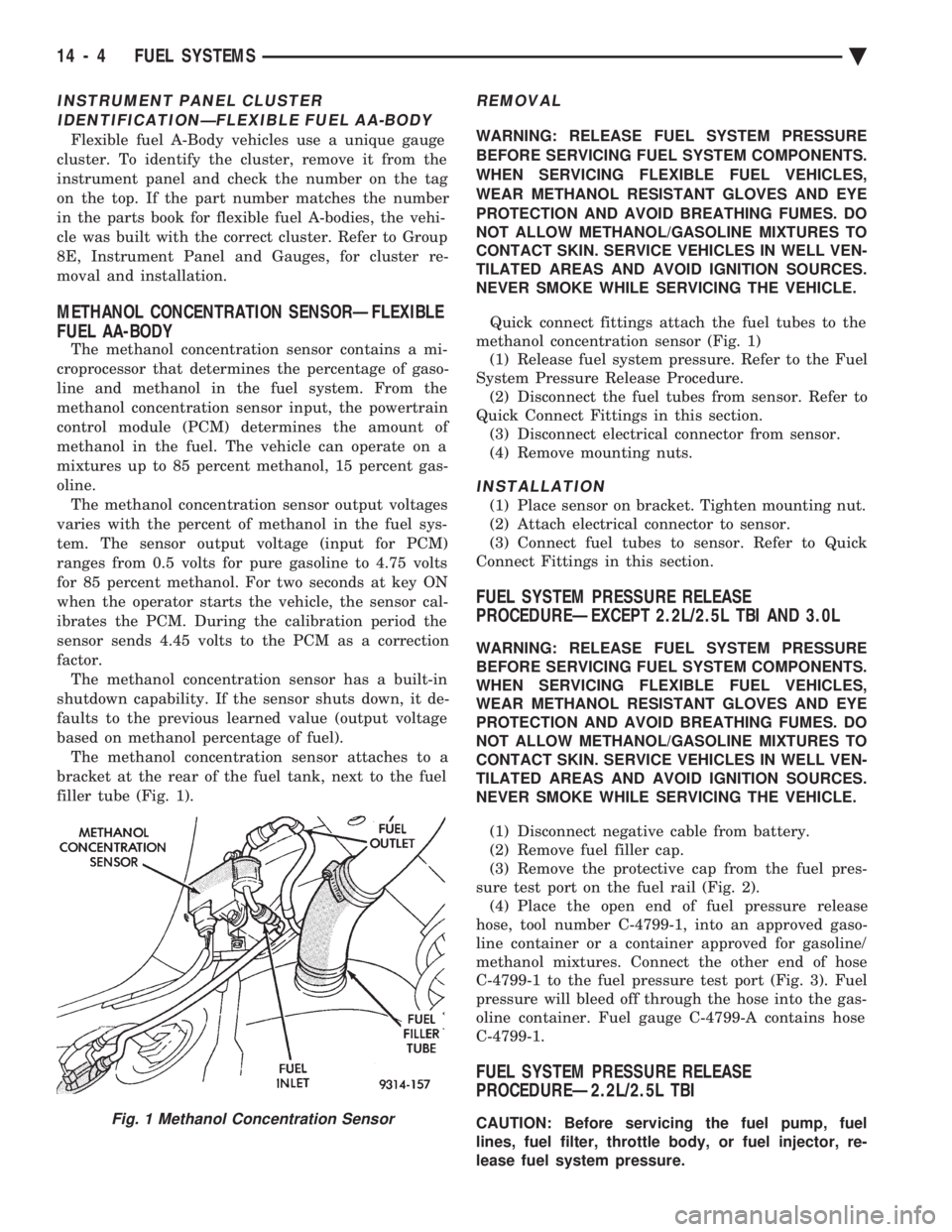
based on methanol percentage of fuel). The methanol concentration sensor attaches to a
bracket at the rear of the fuel tank, next to the fuel
filler tube (Fig. 1).
REMOVAL
WARNING: RELEASE FUEL SYSTEM PRESSURE
BEFORE SERVICING FUEL SYSTEM COMPONENTS.
WHEN SERVICING FLEXIBLE FUEL VEHICLES,
WEAR METHANOL RESISTANT GLOVES AND EYE
PROTECTION AND AVOID BREATHING FUMES. DO
NOT ALLOW METHANOL/GASOLINE MIXTURES TO
CONTACT SKIN. SERVICE VEHICLES IN WELL VEN-
TILATED AREAS AND AVOID IGNITION SOURCES.
NEVER SMOKE WHILE SERVICING THE VEHICLE.
Quick connect fittings attach the fuel tubes to the
methanol concentration sensor (Fig. 1) (1) Release fuel system pressure. Refer to the Fuel
System Pressure Release Procedure. (2) Disconnect the fuel tubes from sensor. Refer to
Quick Connect Fittings in this section. (3) Disconnect electrical connector from sensor.
(4) Remove mounting nuts.
INSTALLATION
(1) Place sensor on bracket. Tighten mounting nut.
(2) Attach electrical connector to sensor.
(3) Connect fuel tubes to sensor. Refer to Quick
Connect Fittings in this section.
FUEL SYSTEM PRESSURE RELEASE
PROCEDUREÐEXCEPT 2.2L/2.5L TBI AND 3.0L
WARNING: RELEASE FUEL SYSTEM PRESSURE
BEFORE SERVICING FUEL SYSTEM COMPONENTS.
WHEN SERVICING FLEXIBLE FUEL VEHICLES,
WEAR METHANOL RESISTANT GLOVES AND EYE
PROTECTION AND AVOID BREATHING FUMES. DO
NOT ALLOW METHANOL/GASOLINE MIXTURES TO
CONTACT SKIN. SERVICE VEHICLES IN WELL VEN-
TILATED AREAS AND AVOID IGNITION SOURCES.
NEVER SMOKE WHILE SERVICING THE VEHICLE.
(1) Disconnect negative cable from battery.
(2) Remove fuel filler cap.
(3) Remove the protective cap from the fuel pres-
sure test port on the fuel rail (Fig. 2). (4) Place the open end of fuel pressure release
hose, tool number C-4799-1, into an approved gaso-
line container or a container approved for gasoline/
methanol mixtures. Connect the other end of hose
C-4799-1 to the fuel pressure test port (Fig. 3). Fuel
pressure will bleed off through the hose into the gas-
oline container. Fuel gauge C-4799-A contains hose
C-4799-1.
FUEL SYSTEM PRESSURE RELEASE
PROCEDUREÐ2.2L/2.5L TBI
CAUTION: Before servicing the fuel pump, fuel
lines, fuel filter, throttle body, or fuel injector, re-
lease fuel system pressure.Fig. 1 Methanol Concentration Sensor
14 - 4 FUEL SYSTEMS Ä
Page 1754 of 2438
FUEL TANKS INDEX
page page
Flexible Fuel Vehicles ..................... 14
Fuel Pump Module ....................... 18
Fuel Reservoir ........................... 18
Fuel System Pressure Release ProcedureÐ 2.2L/2.5L TBI .......................... 15
Fuel System Pressure Release ProcedureÐ3.0L . 15
Fuel System Pressure Release ProcedureÐ Except 2.2L/2.5L TBI and 3.0L ............. 15 Fuel Tank
.............................. 16
Fuel Tank Level Sensor ................... 18
Fuel Tank Pressure Relief and Roll-Over Valve . . 20
General Information ....................... 14
Identifying Flexible Fuel Components .......... 14
Methanol Concentration Sensor .............. 18
Pressure Vacuum Fuel Filler Tube Cap ........ 14
Service Precautions for Flexible Fuel Vehicles . . . 14
GENERAL INFORMATION
The fuel tanks of Chrysler Corporation built vehi-
cles are equipped with fuel and vapor controls that
allow the vehicle to pass a full 360É rollover. The fuel delivery system used on front wheel drive
vehicles contains a fuel tank pressure relief/rollover
valve. The valve mounts on the top of the fuel tank.
The valve functions as a pressure relief valve while
the vehicle is upright. The valve also contains a
check valve that prevents fuel from escaping the fuel
tank if the vehicle turns over. The fuel filler cap also acts as a pressure/vacuum
valve. When pressure inside the fuel tank gets too
high or too low, the fuel filler cap opens to relieve
the difference in air pressure. An evaporation control system restricts fuel evapo-
ration into the atmosphere and reduces unburned hy-
drocarbons. Vapors from the fuel tank are collected
in a charcoal filled canister. The vapors are held in
the canister until the engine is operating. When the
engine operates, vapors are drawn through the in-
take manifold into the combustion chambers.
FLEXIBLE FUEL VEHICLES
Beginning this model year, Chrysler began produc-
ing AA-Body vehicles designed to operate on a mix-
ture of gasoline and methanol. These automobiles are
referred to as Flexible Fuel Vehicles. Flexible fuel vehicles can operate on a mixture of
up to 85 percent methanol, 15 percent unleaded gas-
oline. These vehicles also operate on mixtures con-
taining a lower percentage of methanol or just pure
unleaded gasoline. In many cases, the procedures for servicing flexible
fuel components is identical to gasoline only compo-
nents. Refer to the particular Service Procedure in
this section. If the service procedure for flexible fuel
component differs from a gasoline only component,
the title of each service procedure identifies the ap-
plication.
IDENTIFYING FLEXIBLE FUEL COMPONENTS
Flexible Fuel vehicles have unique methanol com-
patible fuel system components. Chrysler identifies
methanol compatible components that could be phys-
ically interchanged with gasoline only parts by color-
ing them green or applying a green label or tag to
them. Even though they may appear physically iden-
tical, components for gasoline only AA-body vehicles
must not be used on flexible fuel vehicles.
SERVICE PRECAUTIONS FOR FLEXIBLE FUEL
VEHICLES
Methanol is more toxic than gasoline. Always re-
lease fuel system pressure before servicing fuel sys-
tem components and wear methanol resistant gloves
and eye protection. Avoid breathing methanol vapors or ingesting
methanol. Headaches, dizziness and even uncon-
sciousness could result from breathing these vapors.
Serious injury, blindness and even death could result
from ingesting methanol. Methanol vapors are extremely flammable and can
travel along the ground. Service vehicles in well ven-
tilated areas and avoid ignition sources. Never
smoke while servicing the vehicle. Do not allow methanol to contact skin. Prolonged
contact with methanol can cause dry skin or an al-
lergic skin reaction. Also, prolonged contact could re-
sult in absorption through the skin.
PRESSURE VACUUM FUEL FILLER TUBE CAP
WARNING: REMOVE FUEL FILLER TUBE CAP TO
RELIEVE TANK PRESSURE BEFORE REMOVING
OR REPAIRING FUEL SYSTEM COMPONENTS.
The loss of any fuel or vapor out of the filler tube
neck is prevented by the use of a safety filler cap.
The cap releases only under significant pressure 10.9
to 13.45 kPa (1.58 to 1.95 psi). The vacuum release
for all gas caps is between .97 and 2.0 kPa (.14 and
.29 psi). The cap must be replaced by a similar unit
in order for the system to remain effective.
14 - 14 FUEL SYSTEMS Ä
Page 1755 of 2438
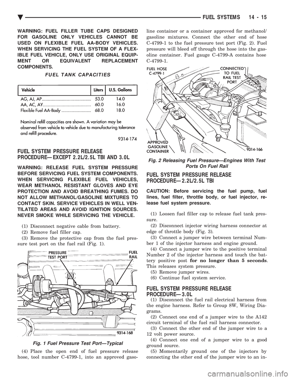
WARNING: FUEL FILLER TUBE CAPS DESIGNED
FOR GASOLINE ONLY VEHICLES CANNOT BE
USED ON FLEXIBLE FUEL AA-BODY VEHICLES.
WHEN SERVICING THE FUEL SYSTEM OF A FLEX-
IBLE FUEL VEHICLE, ONLY USE ORIGINAL EQUIP-
MENT OR EQUIVALENT REPLACEMENT
COMPONENTS.
FUEL SYSTEM PRESSURE RELEASE
PROCEDUREÐEXCEPT 2.2L/2.5L TBI AND 3.0L
WARNING: RELEASE FUEL SYSTEM PRESSURE
BEFORE SERVICING FUEL SYSTEM COMPONENTS.
WHEN SERVICING FLEXIBLE FUEL VEHICLES,
WEAR METHANOL RESISTANT GLOVES AND EYE
PROTECTION AND AVOID BREATHING FUMES. DO
NOT ALLOW METHANOL/GASOLINE MIXTURES TO
CONTACT SKIN. SERVICE VEHICLES IN WELL VEN-
TILATED AREAS AND AVOID IGNITION SOURCES.
NEVER SMOKE WHILE SERVICING THE VEHICLE.
(1) Disconnect negative cable from battery.
(2) Remove fuel filler cap.
(3) Remove the protective cap from the fuel pres-
sure test port on the fuel rail (Fig. 1).
(4) Place the open end of fuel pressure release
hose, tool number C-4799-1, into an approved gaso- line container or a container approved for methanol/
gasoline mixtures. Connect the other end of hose
C-4799-1 to the fuel pressure test port (Fig. 2). Fuel
pressure will bleed off through the hose into the gas-
oline container. Fuel gauge C-4799-A contains hose
C-4799-1.
FUEL SYSTEM PRESSURE RELEASE
PROCEDUREÐ2.2L/2.5L TBI
CAUTION: Before servicing the fuel pump, fuel
lines, fuel filter, throttle body, or fuel injector, re-
lease fuel system pressure.
(1) Loosen fuel filler cap to release fuel tank pres-
sure. (2) Disconnect injector wiring harness connector at
edge of throttle body (Fig. 3). (3) Connect a jumper wire between terminal Num-
ber 1 of the injector harness and engine ground. (4) Connect a jumper wire to the positive terminal
Number 2 of the injector harness and touch the bat-
tery positive post for no longer than 5 seconds .
This releases system pressure. (5) Remove jumper wires.
(6) Continue fuel system service.
FUEL SYSTEM PRESSURE RELEASE
PROCEDUREÐ3.0L
(1) Disconnect the fuel rail electrical harness from
the engine harness. Refer to Group 8W, Wiring Dia-
grams. (2) Connect one end of a jumper wire to the A142
circuit terminal of the fuel rail harness connector. (3) Connect the other end of the jumper wire to a
12 volt power source. (4) Connect one end of a jumper wire to a good
ground source. (5) Momentarily ground one of the injectors by
connecting the other end of the jumper wire to an in-
FUEL TANK CAPACITIES
Fig. 1 Fuel Pressure Test PortÐTypical
Fig. 2 Releasing Fuel PressureÐEngines With Test Ports On Fuel Rail
Ä FUEL SYSTEMS 14 - 15
Page 1758 of 2438
INSTALLATION
WARNING: FUEL TANKS DESIGNED FOR GASO-
LINE ONLY VEHICLES CANNOT BE USED ON
FLEXIBLE FUEL AA-BODY VEHICLES. WHEN SER-
VICING THE FUEL SYSTEM OF A FLEXIBLE FUEL
VEHICLE, ONLY USE ORIGINAL EQUIPMENT OR
EQUIVALENT REPLACEMENT COMPONENTS. (1) Position fuel tank on transmission jack. Con-
nect vapor separator/rollover valve hose and position
insulator pad on fuel tank. Position vapor vent so
that it is not pinched between tank and floor pan
during installation. (2) Raise tank and fuel filler tube carefully into
position. Use a light coating of power steering fluid
to ease fuel filler tube installation. Ensure filler tube
grommet is not damaged. Verify that the tube is in-
stalled correctly. (3) Tighten fuel tank strap nuts to 23 N Im (250 in.
lbs.) torque. Remove transmission jack. Ensure
straps are not twisted or bent. (4) Lubricate the metal tubes on the fuel pump
with clean 30 weight engine oil. Install the quick
connect fuel fittings. Refer to Quick Connect Fittings
in the Fuel Delivery section of this Group. (5) Attach electrical connector to fuel pump mod-
ule and level sensor unit. (6) Lower the vehicle.
(7) Attach filler tube to filler neck opening in
quarter panel. Tighten quarter panel screws to 2
N Im (17 in. lbs.) torque.
(8) Fill fuel tank, install filler cap, and connect
battery cable.
CAUTION: When using the ASD Fuel System Test,
the Auto Shutdown (ASD) Relay remains energized
for either 7 minutes, until the test is stopped, or un-
til the ignition switch is turned to the Off position.
(9) Use the DRBII scan tool ASD Fuel System Test
to pressurize the fuel system. Check for leaks.
FUEL PUMP MODULE
Refer to the Fuel Delivery section of this group.
METHANOL CONCENTRATION SENSOR
Refer to the Fuel Delivery section of this group.
FUEL RESERVOIR
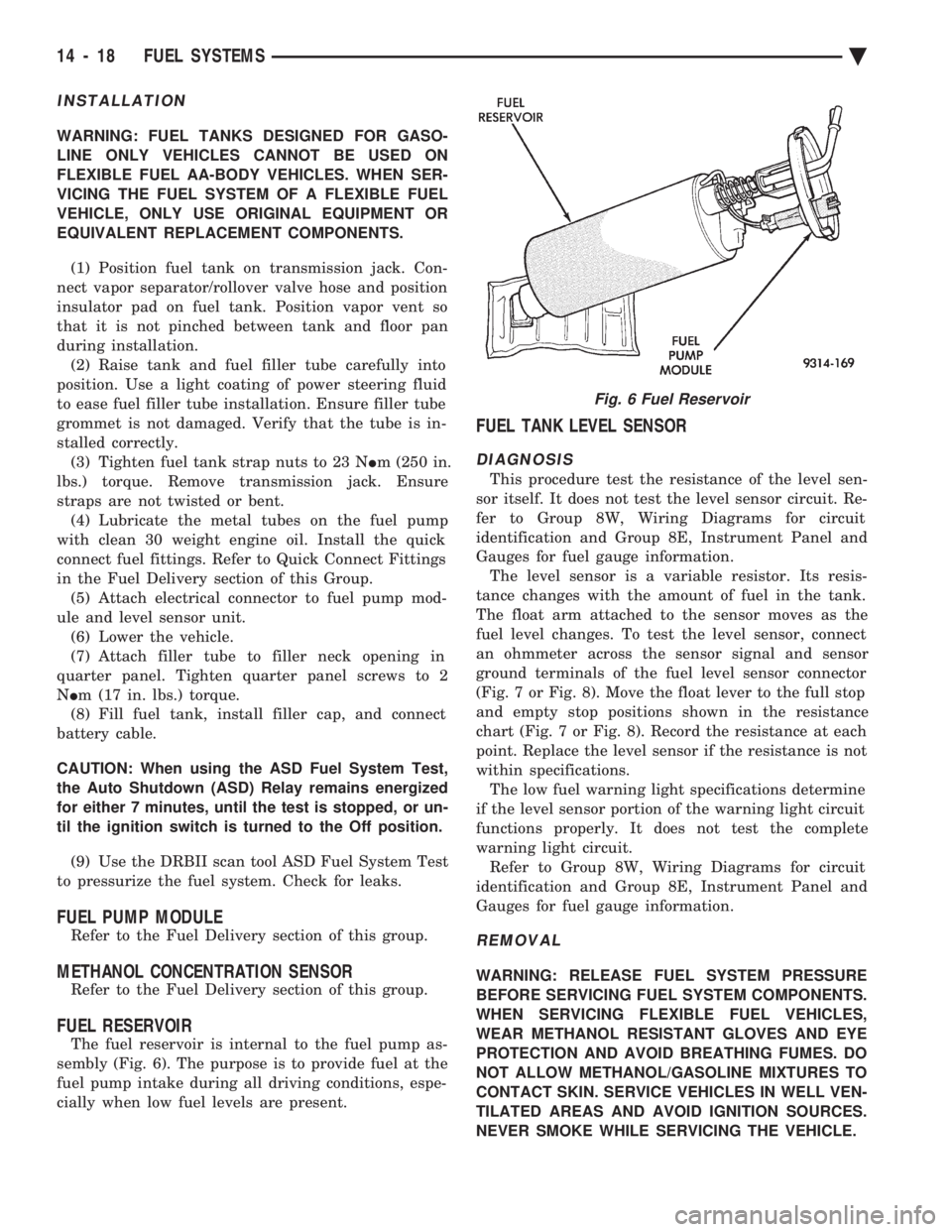
The fuel reservoir is internal to the fuel pump as-
sembly (Fig. 6). The purpose is to provide fuel at the
fuel pump intake during all driving conditions, espe-
cially when low fuel levels are present.
FUEL TANK LEVEL SENSOR
DIAGNOSIS
This procedure test the resistance of the level sen-
sor itself. It does not test the level sensor circuit. Re-
fer to Group 8W, Wiring Diagrams for circuit
identification and Group 8E, Instrument Panel and
Gauges for fuel gauge information. The level sensor is a variable resistor. Its resis-
tance changes with the amount of fuel in the tank.
The float arm attached to the sensor moves as the
fuel level changes. To test the level sensor, connect
an ohmmeter across the sensor signal and sensor
ground terminals of the fuel level sensor connector
(Fig. 7 or Fig. 8). Move the float lever to the full stop
and empty stop positions shown in the resistance
chart (Fig. 7 or Fig. 8). Record the resistance at each
point. Replace the level sensor if the resistance is not
within specifications. The low fuel warning light specifications determine
if the level sensor portion of the warning light circuit
functions properly. It does not test the complete
warning light circuit. Refer to Group 8W, Wiring Diagrams for circuit
identification and Group 8E, Instrument Panel and
Gauges for fuel gauge information.
REMOVAL
WARNING: RELEASE FUEL SYSTEM PRESSURE
BEFORE SERVICING FUEL SYSTEM COMPONENTS.
WHEN SERVICING FLEXIBLE FUEL VEHICLES,
WEAR METHANOL RESISTANT GLOVES AND EYE
PROTECTION AND AVOID BREATHING FUMES. DO
NOT ALLOW METHANOL/GASOLINE MIXTURES TO
CONTACT SKIN. SERVICE VEHICLES IN WELL VEN-
TILATED AREAS AND AVOID IGNITION SOURCES.
NEVER SMOKE WHILE SERVICING THE VEHICLE.
Fig. 6 Fuel Reservoir
14 - 18 FUEL SYSTEMS Ä
Page 1761 of 2438
INSTALLATION
WARNING: FUEL PRESSURE RELIEF/ROLLOVER
VALVES DESIGNED FOR GASOLINE ONLY VEHI-
CLES CANNOT BE USED ON FLEXIBLE FUEL AA-
BODY VEHICLES. WHEN SERVICING THE FUEL
SYSTEM OF A FLEXIBLE FUEL VEHICLE, ONLY
USE ORIGINAL EQUIPMENT OR EQUIVALENT RE-
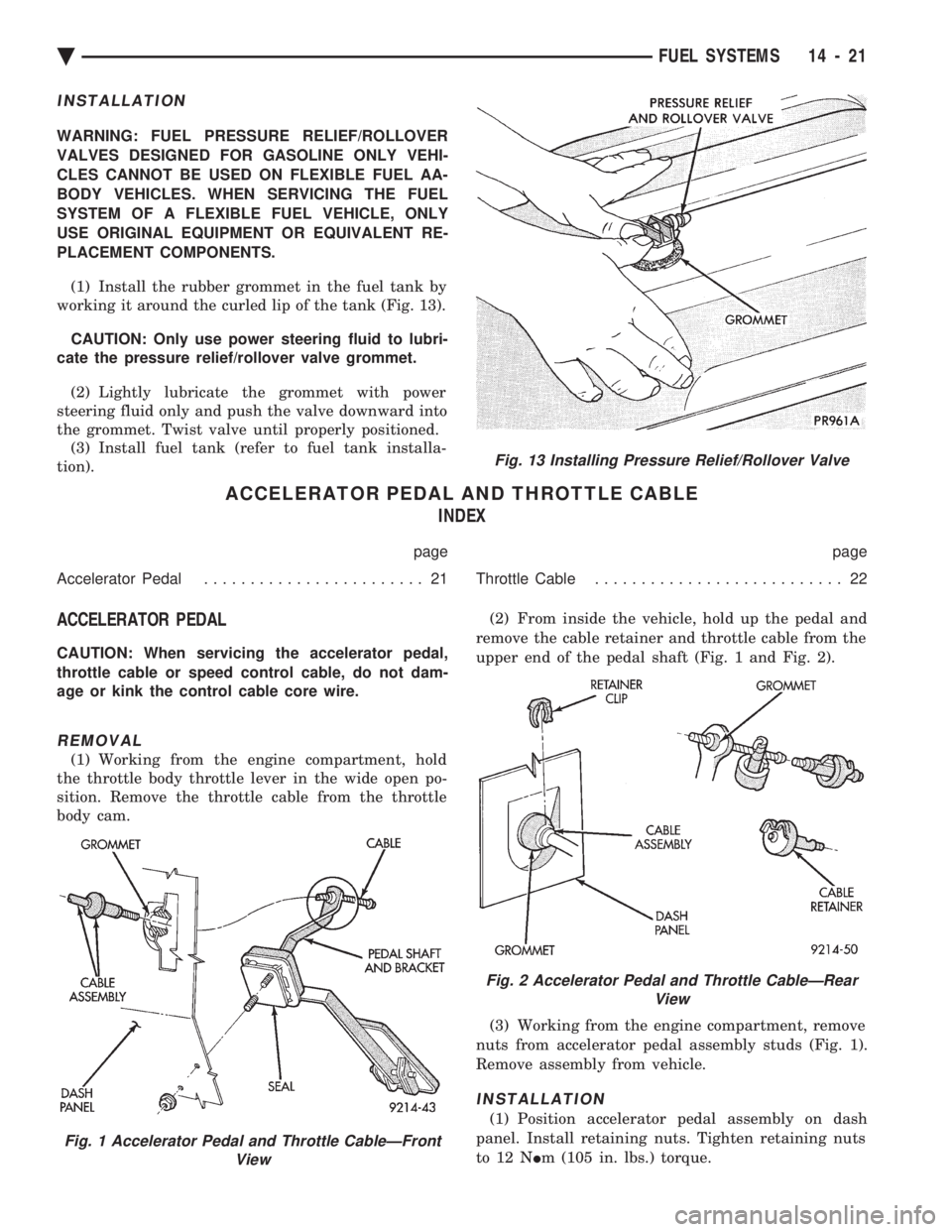
PLACEMENT COMPONENTS. (1) Install the rubber grommet in the fuel tank by
working it around the curled lip of the tank (Fig. 13).
CAUTION: Only use power steering fluid to lubri-
cate the pressure relief/rollover valve grommet.
(2) Lightly lubricate the grommet with power
steering fluid only and push the valve downward into
the grommet. Twist valve until properly positioned. (3) Install fuel tank (refer to fuel tank installa-
tion).
ACCELERATOR PEDAL AND THROTTLE CABLE INDEX
page page
Accelerator Pedal ........................ 21 Throttle Cable........................... 22
ACCELERATOR PEDAL
CAUTION: When servicing the accelerator pedal,
throttle cable or speed control cable, do not dam-
age or kink the control cable core wire.
REMOVAL
(1) Working from the engine compartment, hold
the throttle body throttle lever in the wide open po-
sition. Remove the throttle cable from the throttle
body cam. (2) From inside the vehicle, hold up the pedal and
remove the cable retainer and throttle cable from the
upper end of the pedal shaft (Fig. 1 and Fig. 2).
(3) Working from the engine compartment, remove
nuts from accelerator pedal assembly studs (Fig. 1).
Remove assembly from vehicle.
INSTALLATION
(1) Position accelerator pedal assembly on dash
panel. Install retaining nuts. Tighten retaining nuts
to 12 N Im (105 in. lbs.) torque.
Fig. 1 Accelerator Pedal and Throttle CableÐFront
View
Fig. 13 Installing Pressure Relief/Rollover Valve
Fig. 2 Accelerator Pedal and Throttle CableÐRearView
Ä FUEL SYSTEMS 14 - 21