Page 1805 of 2438
The exhaust gas oxygen content input is not ac-
cepted by the PCM during wide open throttle opera-
tion. The PCM will enrichen the air/fuel ratio to
increase performance and compensate for increased
combustion chamber temperature. The PCM determines the methanol content of the
fuel from the methanol concentration sensor input.
IGNITION SWITCH OFF MODE
This is an OPEN LOOP mode. When the ignition
switch is turned to the OFF position, the following
occurs:
² All outputs are turned off.
² No inputs are monitored.
² The PCM shuts down.
THROTTLE BODY
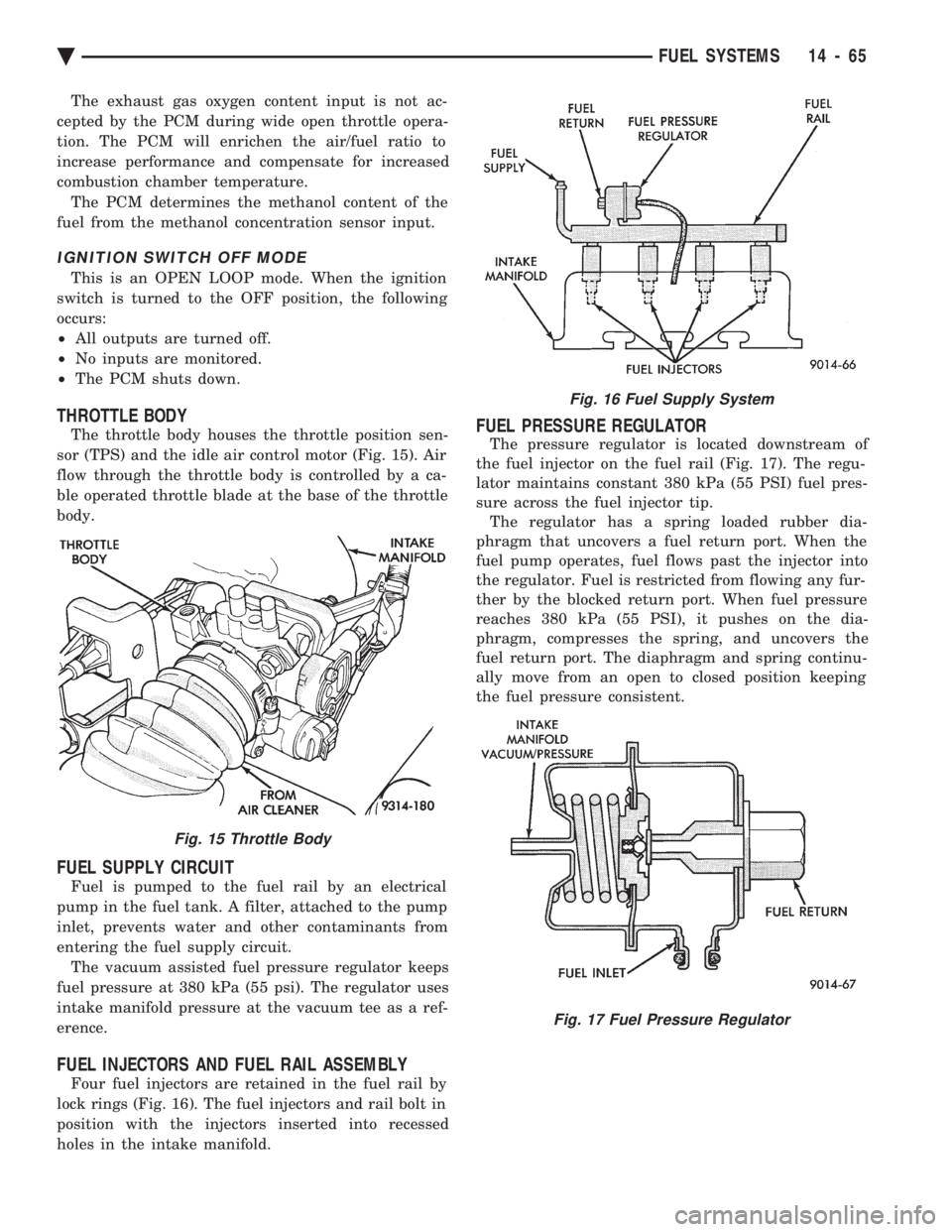
The throttle body houses the throttle position sen-
sor (TPS) and the idle air control motor (Fig. 15). Air
flow through the throttle body is controlled by a ca-
ble operated throttle blade at the base of the throttle
body.
FUEL SUPPLY CIRCUIT
Fuel is pumped to the fuel rail by an electrical
pump in the fuel tank. A filter, attached to the pump
inlet, prevents water and other contaminants from
entering the fuel supply circuit. The vacuum assisted fuel pressure regulator keeps
fuel pressure at 380 kPa (55 psi). The regulator uses
intake manifold pressure at the vacuum tee as a ref-
erence.
FUEL INJECTORS AND FUEL RAIL ASSEMBLY
Four fuel injectors are retained in the fuel rail by
lock rings (Fig. 16). The fuel injectors and rail bolt in
position with the injectors inserted into recessed
holes in the intake manifold.
FUEL PRESSURE REGULATOR
The pressure regulator is located downstream of
the fuel injector on the fuel rail (Fig. 17). The regu-
lator maintains constant 380 kPa (55 PSI) fuel pres-
sure across the fuel injector tip. The regulator has a spring loaded rubber dia-
phragm that uncovers a fuel return port. When the
fuel pump operates, fuel flows past the injector into
the regulator. Fuel is restricted from flowing any fur-
ther by the blocked return port. When fuel pressure
reaches 380 kPa (55 PSI), it pushes on the dia-
phragm, compresses the spring, and uncovers the
fuel return port. The diaphragm and spring continu-
ally move from an open to closed position keeping
the fuel pressure consistent.
Fig. 15 Throttle Body
Fig. 16 Fuel Supply System
Fig. 17 Fuel Pressure Regulator
Ä FUEL SYSTEMS 14 - 65
Page 1863 of 2438
The PCM may receive a closed throttle input from
the throttle position sensor (TPS) when it senses an
abrupt decrease in manifold pressure. This indicates
a hard deceleration. The PCM may reduce injector
firing to once per engine revolution. This helps main-
tain better control of the air-fuel mixture. During a deceleration condition, the PCM grounds
the exhaust gas recirculation (EGR) solenoid. When
the PCM grounds the solenoid, preventing EGR.
WIDE OPEN THROTTLE MODE This is an OPEN LOOP mode. During wide-open-
throttle operation, the following inputs are received
by the PCM:
² engine coolant temperature
² crankshaft position (distributor pick-up)
² manifold absolute pressure
² engine speed (distributor pick-up)
² throttle position
When the PCM senses wide open throttle condition
through the throttle position sensor (TPS) it will:
² Provide a ground for the electrical EGR transducer
(EET) solenoid. When the PCM grounds the solenoid,
the EGR system stops operating.
² De-energize the air conditioning relay. This dis-
ables the air conditioning system. The exhaust gas oxygen content input is not ac-
cepted by the PCM during wide open throttle opera- tion. The PCM will adjust injector pulse width to
supply a predetermined amount of additional fuel.
IGNITION SWITCH OFF MODE
When the ignition switch is turned to the OFF po-
sition, the following occurs:
² All outputs are turned off.
² No inputs are monitored.
² The PCM shuts down.
THROTTLE BODY
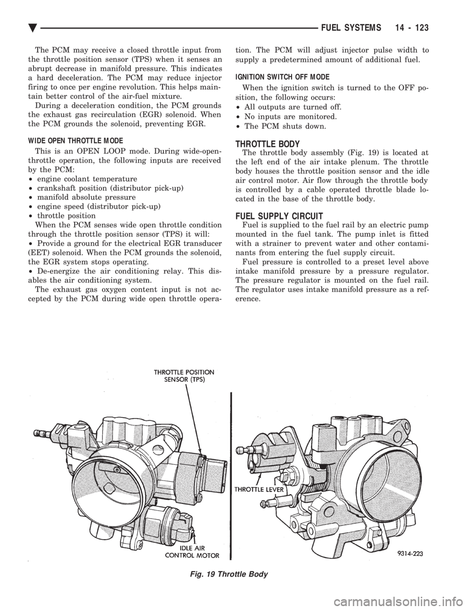
The throttle body assembly (Fig. 19) is located at
the left end of the air intake plenum. The throttle
body houses the throttle position sensor and the idle
air control motor. Air flow through the throttle body
is controlled by a cable operated throttle blade lo-
cated in the base of the throttle body.
FUEL SUPPLY CIRCUIT
Fuel is supplied to the fuel rail by an electric pump
mounted in the fuel tank. The pump inlet is fitted
with a strainer to prevent water and other contami-
nants from entering the fuel supply circuit. Fuel pressure is controlled to a preset level above
intake manifold pressure by a pressure regulator.
The pressure regulator is mounted on the fuel rail.
The regulator uses intake manifold pressure as a ref-
erence.
Fig. 19 Throttle Body
Ä FUEL SYSTEMS 14 - 123
Page 1895 of 2438
WIDE OPEN THROTTLE MODE This is an OPEN LOOP mode. During wide-open-
throttle operation, the following inputs are received
by the PCM:
² battery voltage
² engine coolant temperature
² manifold absolute pressure
² engine speed
² throttle position
When the PCM senses wide open throttle condition
through the throttle position sensor (TPS) it will:
² De-energize the air conditioning relay. This dis-
ables the air conditioning system.
² Provide a ground for the electrical EGR transducer
(EET) solenoid. When the PCM grounds the solenoid,
the EGR system stops operating. The exhaust gas oxygen content input is not ac-
cepted by the PCM during wide open throttle opera-
tion. The PCM will adjust injector pulse width to
supply a predetermined amount of additional fuel.
IGNITION SWITCH OFF MODE When the ignition switch is turned to the OFF po-
sition, the following occurs:
² All outputs are turned off.
² No inputs are monitored.
² The PCM shuts down.
THROTTLE BODY
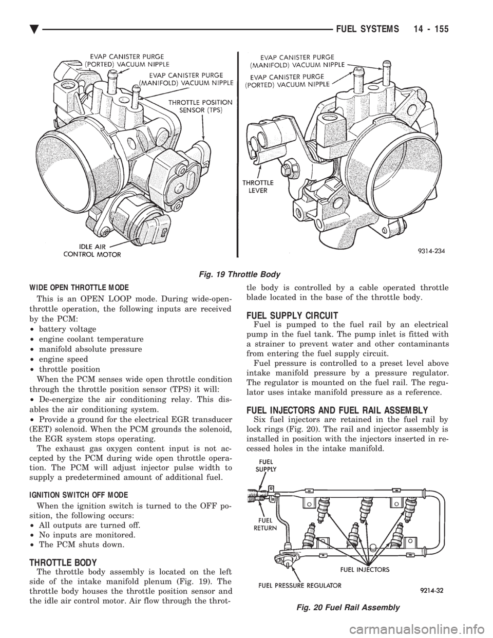
The throttle body assembly is located on the left
side of the intake manifold plenum (Fig. 19). The
throttle body houses the throttle position sensor and
the idle air control motor. Air flow through the throt- tle body is controlled by a cable operated throttle
blade located in the base of the throttle body.
FUEL SUPPLY CIRCUIT
Fuel is pumped to the fuel rail by an electrical
pump in the fuel tank. The pump inlet is fitted with
a strainer to prevent water and other contaminants
from entering the fuel supply circuit. Fuel pressure is controlled to a preset level above
intake manifold pressure by a pressure regulator.
The regulator is mounted on the fuel rail. The regu-
lator uses intake manifold pressure as a reference.
FUEL INJECTORS AND FUEL RAIL ASSEMBLY
Six fuel injectors are retained in the fuel rail by
lock rings (Fig. 20). The rail and injector assembly is
installed in position with the injectors inserted in re-
cessed holes in the intake manifold.
Fig. 19 Throttle Body
Fig. 20 Fuel Rail Assembly
Ä FUEL SYSTEMS 14 - 155