1993 CHEVROLET DYNASTY height
[x] Cancel search: heightPage 58 of 2438
BRAKE RESERVOIR LEVEL INSPECTION
WARNING: DO NOT ALLOW PETROLEUM OR WATER
BASE LIQUIDS TO CONTAMINATE BRAKE FLUID,
SEAL DAMAGE AND BRAKE FAILURE CAN RESULT.
RELIEVE PRESSURE IN ANTI-LOCK BRAKE SYS-
TEM BEFORE ADDING BRAKE FLUID TO RESER-
VOIR. IF NOT, BRAKE FLUID COULD DISCHARGED
FROM THE RESERVOIR POSSIBLY CAUSING PER-
SONAL INJURY.
The brake reservoir level should be inspected when
other under hood service is performed. It is normal
for the reservoir level to drop as disc brake pads
wear. When fluid must be added, use Mopar, Brake
Fluid or equivalent. Use only brake fluid conforming
to DOT 3, Federal, Department of Transportation
specification. To avoid brake fluid contamination, use
fluid from a properly sealed container. On vehicles with anti-lock brakes, depressurize the
system before inspecting fluid level. Turn OFF the
ignition and remove the key. Pump the brake pedal
at least 50 times to relieve the pressure in the sys-
tem.
On all vehicles, if fluid should become low after sev-
eral thousand kilometers (miles), fill the reservoir to
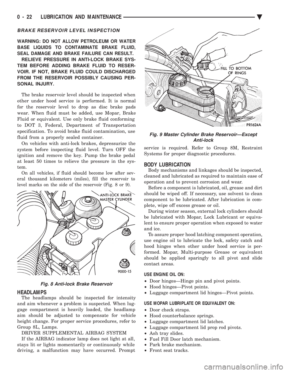
level marks on the side of the reservoir (Fig. 8 or 9).
HEADLAMPS
The headlamps should be inspected for intensity
and aim whenever a problem is suspected. When lug-
gage compartment is heavily loaded, the headlamp
aim should be adjusted to compensate for vehicle
height change. For proper service procedures, refer to
Group 8L, Lamps. DRIVER SUPPLEMENTAL AIRBAG SYSTEM
If the AIRBAG indicator lamp does not light at all,
stays lit or lights momentarily or continuously while
driving, a malfunction may have occurred. Prompt service is required. Refer to Group 8M, Restraint
Systems for proper diagnostic procedures.
BODY LUBRICATION
Body mechanisms and linkages should be inspected,
cleaned and lubricated as required to maintain ease of
operation and to prevent corrosion and wear. Before a component is lubricated, oil, grease and dirt
should be wiped off. If necessary, use solvent to clean
component to be lubricated. After lubrication is com-
plete, wipe off excess grease or oil. During winter season, external lock cylinders should
be lubricated with Mopar, Lock Lubricant or equiva-
lent to ensure proper operation when exposed to water
and ice. To assure proper hood latching component operation,
use engine oil to lubricate the lock, safety catch and
hood hinges when other under hood service is per-
formed. Mopar, Multi-purpose Grease or equivalent
should be applied sparingly to all pivot and slide
contact areas.
USE ENGINE OIL ON:
² Door hingesÐHinge pin and pivot points.
² Hood hingesÐPivot points.
² Luggage compartment lid hingesÐPivot points.
USE MOPAR LUBRIPLATE OR EQUIVALENT ON:
² Door check straps.
² Hood counterbalance springs.
² Luggage compartment lid latches.
² Luggage compartment lid prop rod pivots.
² Ash tray slides.
² Fuel Fill Door latch mechanism.
² Park brake mechanism.
² Front seat tracks.
Fig. 8 Anti-lock Brake Reservoir
Fig. 9 Master Cylinder Brake ReservoirÐExcept
Anti-lock
0 - 22 LUBRICATION AND MAINTENANCE Ä
Page 63 of 2438
FRONT SUSPENSION SERVICE PROCEDURES INDEX
page page
Ball Joints .............................. 13
Hub and Bearing Assembly ................. 20
Knuckle (Front Suspension) ................. 16
Lower Control Arm ....................... 10
Lower Control Arm Pivot Bushings ........... 11 Shock Absorbers (Strut Damper)
............. 10
Strut Damper Assembly ..................... 7
Suspension Coil Springs .................... 9
Sway Bar .............................. 14
Wheel Alignment .......................... 5
WHEEL ALIGNMENT
Front wheel alignment is the proper adjustment of
all interrelated front suspension angles. These angles
are what affects the running and steering of the
front wheels of the vehicle. The method of checking front alignment will vary
depending on the type of equipment being used. The
instructions furnished by the manufacturer of the
equipment should always be followed. With the ex-
ception that the alignment specifications recom-
mended by Chrysler Corporation be used. There are six basic factors which are the founda-
tion to front wheel alignment. These are height,
caster, camber, toe-in, steering axis inclination and
toe-out on turns. Of the six basic factors only camber
and toe in are mechanically adjustable (Fig. 1)
CAUTION: Do not attempt to modify any suspen-
sion or steering components by heating or bending
of the component.
Wheel alignment adjustments and checks should be
made in the following sequence. (1) Camber
(2) Toe
Camber is the number of degrees the top of the
wheel is tilted inward or outward from true vertical.
Inward tilt is negative camber. Outward tilt is posi-
tive camber. Excessive camber is a tire wear factor: negative
camber causes wear on the inside of the tire, while
positive camber causes wear to the outside. Toe
is measured in degrees or inches and is the
distance the front edges of the tires are closer (or far-
ther apart) than the rear edges. See Front Wheel
Drive Specifications for Toesettings.
PRE-ALIGNMENT
Before any attempt is made to change or correct
the wheel alignment factors. The following inspection
and necessary corrections must be made on those
parts which influence the steering of the vehicle. (1) Check and inflate tires to recommended pres-
sure. All tires should be the same size and in good
condition and have approximately the same wear.
Note type of tread wear which will aid in diagnosing,
see Wheels and Tires, Group 22. (2) Check front wheel and tire assembly for radial
runout. (3) Inspect lower ball joints and all steering link-
age for looseness. (4) Check for broken or sagged front and rear
springs. Front suspension must only be checked after the
vehicle has had the following checked or adjusted.
Tires set to recommended pressures, full tank of fuel,
no passenger or luggage compartment load and is on
a level floor or alignment rack. Just prior to each alignment reading. The vehicle
should be bounced (rear first, then front) by grasping
bumper at center and jouncing each end an equal
number of times. Always release bumpers at bottom
of down cycle.
Ä SUSPENSION AND DRIVESHAFTS 2 - 5
Page 69 of 2438
Inspect lower control arm for distortion. Check
bushings for severe deterioration.
INSTALLATION (ASSEMBLY)
(1) Position the lower control arm into the cross-
member. Install front and rear pivot bushing to
crossmember attaching bolts. Then loosely assemble
nuts to bolts (Fig. 2). (2) Install ball joint stud into steering knuckle and
install clamp bolt (Fig. 1). Tighten clamp bolt to 145
N Im (105 ft. lbs.).
(3) Position sway bar and bushings against the
lower control arms. Install sway bar to control arm
retainers. Install retainer bolts and tighten to 70
N Im (50 ft. lbs.).
(4) Lower vehicle so the suspension is supporting
vehicles weight (control arm at design height).
Tighten the lower control arm to crossmember at-
taching bolts to 169 N Im (125 ft. lbs.) torque.
LOWER CONTROL ARM PIVOT BUSHINGS
When performing the replacement procedure on the
lower control arm pivot bushings, the following se-
quence must be followed. When removing the pivot
bushings from the lower control arm, the large bush-
ing must be removed first then the small bushing.
When installing the pivot bushings into the lower
control arm, the small bushing must be installed
first then the large bushing. This sequence must be
used when removal and replacement of bushings is
done using Bushing Remover/Installer, Special Tool
6602.
LARGE BUSHING
REMOVE
(1) Position and clamp lower control arm in a vise.
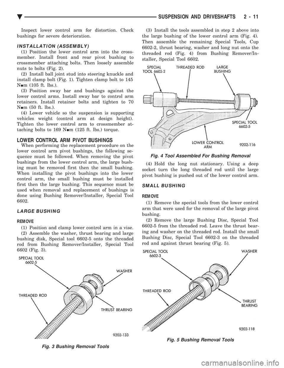
(2) Assemble the washer, thrust bearing and large
bushing disk, Special tool 6602-5 onto the threaded
rod from Bushing Remover/Installer, Special Tool
6602 (Fig. 3). (3) Install the tools assembled in step 2 above into
the large bushing of the lower control arm (Fig. 4).
Then assemble the remaining Special Tools, Cup
6602-2, thrust bearing, washer and long nut onto the
threaded rod (Fig. 4) from Bushing Remover/In-
staller, Special Tool 6602.
(4) Hold the long nut stationary. Using a deep
socket turn the long threaded rod until the large
pivot bushing is pushed out of the lower control arm.
SMALL BUSHING
REMOVE
(1) Remove the special tools from the lower control
arm that were used for the removal of the large pivot
bushing. (2) Remove the large Bushing Disc, Special Tool
6602-5 from the threaded rod. Leave the thrust bear-
ing and washer on the threaded rod. Install the small
Bushing Disc, Special Tool 6602-3 on the threaded
rod and against thrust bearing (Fig. 5).
Fig. 3 Bushing Removal Tools
Fig. 4 Tool Assembled For Bushing Removal
Fig. 5 Bushing Removal Tools
Ä SUSPENSION AND DRIVESHAFTS 2 - 11
Page 74 of 2438
the lower clamps and bolts. The center offset in the
sway bar should be oriented toward the front of the
vehicle (Fig. 16)(3) Position bushing retainers on lower control arms
and install bolts (Fig. 16). (4) With lower control arms raised to design height,
tighten all retainer attaching bolts to 70 N Im (50 ft.
lbs.) torque. (5) Lower vehicle.
KNUCKLE (FRONT SUSPENSION)
The front suspension knuckle (Fig. 1) provides for
steering control of the vehicle. Supports the brake
caliper and absorbs the loads exerted during vehicle
braking. It also supports the front (driving) hub and
bearing and stub axle assembly. The front suspension knuckle also provides the abil-
ity to align the front wheels of the vehicle. This is done
by allowing for front wheel camber adjustment and the
ability for front tire Toe adjustments The front suspension knuckle is not a serviceable
component. Do not attempt to straighten or repair the
front suspension knuckle in any way. Service repair or replacement of the front (drive) hub
and bearing, can be done with the front suspension
knuckle remaining on the vehicle.
REMOVAL
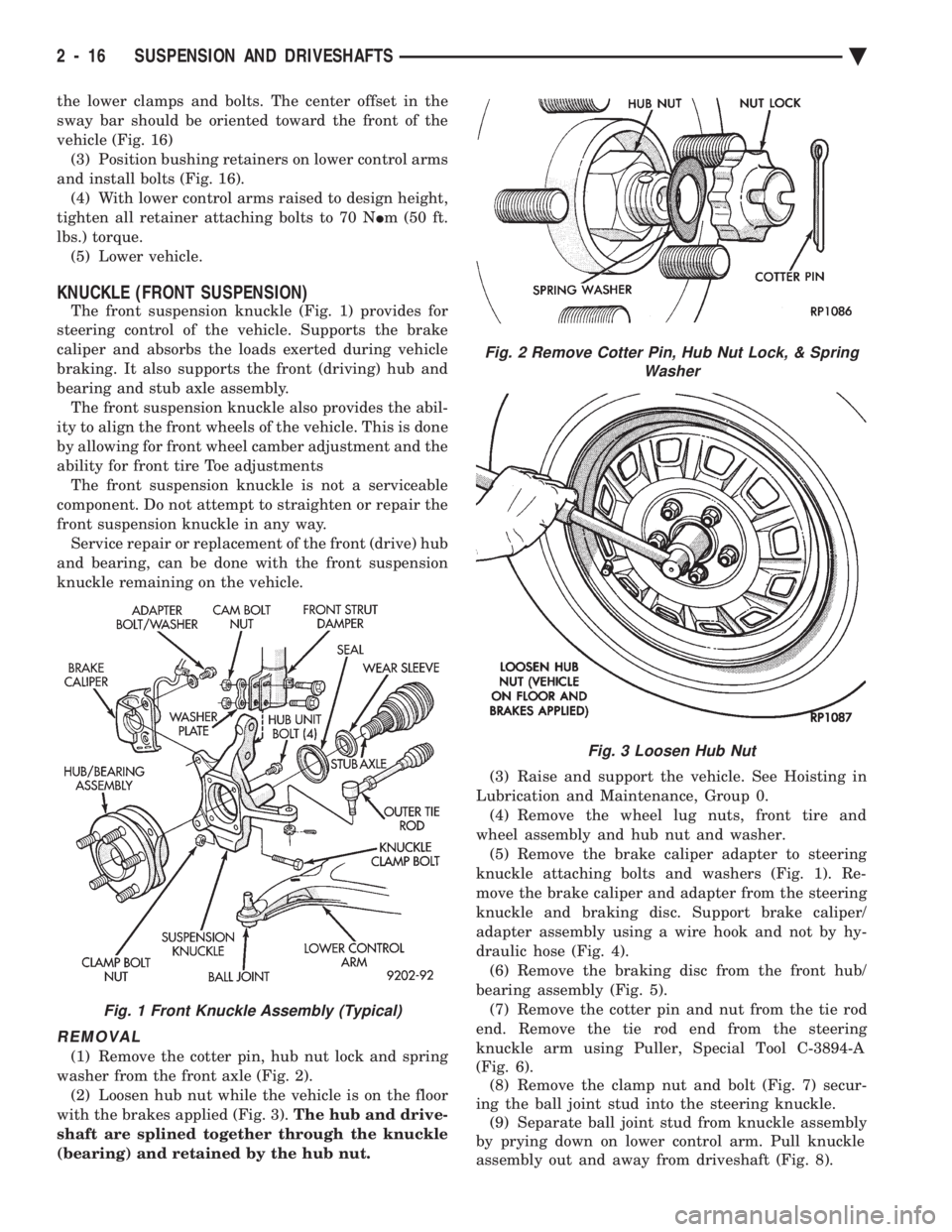
(1) Remove the cotter pin, hub nut lock and spring
washer from the front axle (Fig. 2). (2) Loosen hub nut while the vehicle is on the floor
with the brakes applied (Fig. 3). The hub and drive-
shaft are splined together through the knuckle
(bearing) and retained by the hub nut. (3) Raise and support the vehicle. See Hoisting in
Lubrication and Maintenance, Group 0. (4) Remove the wheel lug nuts, front tire and
wheel assembly and hub nut and washer. (5) Remove the brake caliper adapter to steering
knuckle attaching bolts and washers (Fig. 1). Re-
move the brake caliper and adapter from the steering
knuckle and braking disc. Support brake caliper/
adapter assembly using a wire hook and not by hy-
draulic hose (Fig. 4). (6) Remove the braking disc from the front hub/
bearing assembly (Fig. 5). (7) Remove the cotter pin and nut from the tie rod
end. Remove the tie rod end from the steering
knuckle arm using Puller, Special Tool C-3894-A
(Fig. 6). (8) Remove the clamp nut and bolt (Fig. 7) secur-
ing the ball joint stud into the steering knuckle. (9) Separate ball joint stud from knuckle assembly
by prying down on lower control arm. Pull knuckle
assembly out and away from driveshaft (Fig. 8).
Fig. 2 Remove Cotter Pin, Hub Nut Lock, & Spring Washer
Fig. 3 Loosen Hub Nut
Fig. 1 Front Knuckle Assembly (Typical)
2 - 16 SUSPENSION AND DRIVESHAFTS Ä
Page 110 of 2438
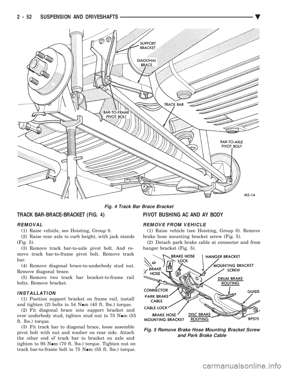
TRACK BAR-BRACE-BRACKET (FIG. 4)
REMOVAL
(1) Raise vehicle, see Hoisting, Group 0.
(2) Raise rear axle to curb height, with jack stands
(Fig. 5). (3) Remove track bar-to-axle pivot bolt. And re-
move track bar-to-frame pivot bolt. Remove track
bar. (4) Remove diagonal brace-to-underbody stud nut.
Remove diagonal brace. (5) Remove two track bar bracket-to-frame rail
bolts. Remove bracket.
INSTALLATION
(1) Position support bracket on frame rail, install
and tighten (2) bolts to 54 N Im (40 ft. lbs.) torque.
(2) Fit diagonal brace into support bracket and
over underbody stud, tighten stud nut to 75 N Im (55
ft. lbs.) torque. (3) Fit track bar to diagonal brace, loose assemble
pivot bolt with nut and washer on rear side. Attach
the other end of track bar to bracket on axle and
tighten to 95 N Im (70 ft. lbs.) torque. Tighten nut on
track bar-to-frame bolt to 75 N Im (55 ft. lbs.) torque.
PIVOT BUSHING AC AND AY BODY
REMOVE FROM VEHICLE
(1) Raise vehicle (see Hoisting, Group 0). Remove
brake hose mounting bracket screw (Fig. 5). (2) Detach park brake cable at connector and from
hanger bracket (Fig. 5).
Fig. 4 Track Bar Brace Bracket
Fig. 5 Remove Brake Hose Mounting Bracket Screw and Park Brake Cable
2 - 52 SUSPENSION AND DRIVESHAFTS Ä
Page 112 of 2438
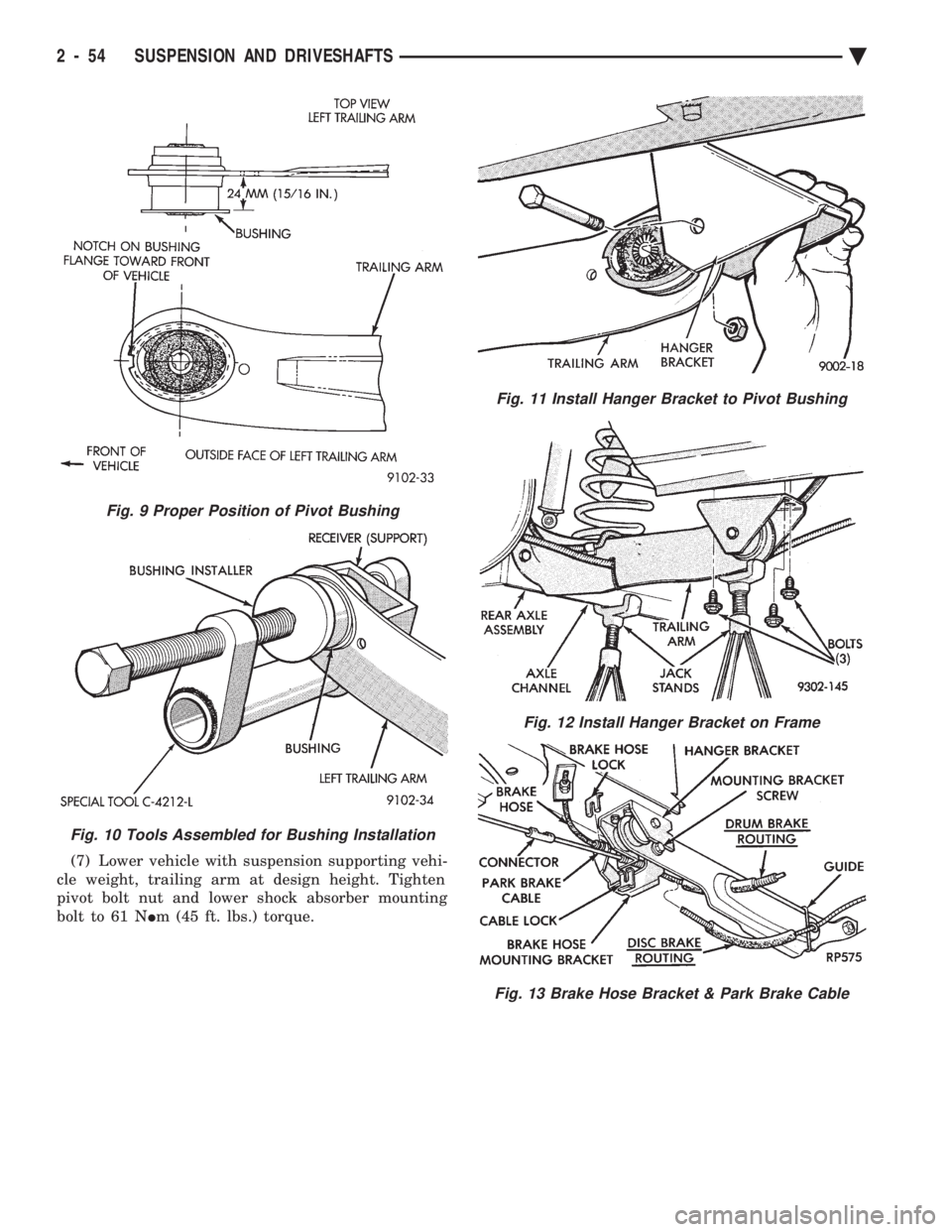
(7) Lower vehicle with suspension supporting vehi-
cle weight, trailing arm at design height. Tighten
pivot bolt nut and lower shock absorber mounting
bolt to 61 N Im (45 ft. lbs.) torque.
Fig. 9 Proper Position of Pivot Bushing
Fig. 10 Tools Assembled for Bushing Installation
Fig. 11 Install Hanger Bracket to Pivot Bushing
Fig. 12 Install Hanger Bracket on Frame
Fig. 13 Brake Hose Bracket & Park Brake Cable
2 - 54 SUSPENSION AND DRIVESHAFTS Ä
Page 114 of 2438
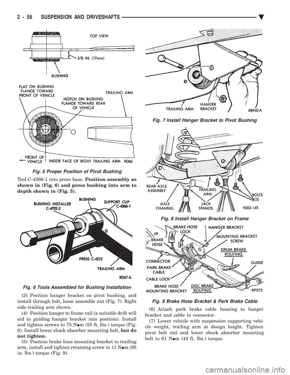
Tool C-4366-1 into press base. Position assembly as
shown in (Fig. 6) and press bushing into arm to
depth shown in (Fig. 5).
(3) Position hanger bracket on pivot bushing, and
install through bolt, loose assemble nut (Fig. 7). Right
side trailing arm shown. (4) Position hanger to frame rail (a suitable drift will
aid in guiding hanger bracket into position). Install
and tighten screws to 75 N Im (55 ft. lbs.) torque (Fig.
8). Install lower shock absorber mounting bolt, but do
not tighten. (5) Position brake hose mounting bracket to trailing
arm, install and tighten retaining screw to 11 N Im (95
in. lbs.) torque (Fig. 9). (6) Attach park brake cable housing to hanger
bracket and cable to connector. (7) Lower vehicle with suspension supporting vehi-
cle weight, trailing arm at design height. Tighten
pivot bolt nut and lower shock absorber mounting
bolt to 61 N Im (45 ft. lbs.) torque.
Fig. 7 Install Hanger Bracket to Pivot Bushing
Fig. 8 Install Hanger Bracket on Frame
Fig. 9 Brake Hose Bracket & Park Brake Cable
Fig. 5 Proper Position of Pivot Bushing
Fig. 6 Tools Assembled for Bushing Installation
2 - 56 SUSPENSION AND DRIVESHAFTS Ä
Page 117 of 2438

AUTOMATIC AIR LOAD LEVELING SYSTEM INDEX
page page
Compressor Performance Test .............. 61
Compressor Relay ........................ 72
Control Module .......................... 72
General Information ....................... 59
Major Components ....................... 59 Rear Leveling Diagnostic Procedures
......... 65
Right Shock Absorber (With Height Sensor) .... 72
Service Procedures ....................... 62
System Operation ........................ 61
GENERAL INFORMATION
The automatic air load leveling system includes
the following (Fig. 1).:
² Compressor Assembly
² Control Module Wiring Harness
² Air Lines
² Compressor Relay
² Air Shock Absorbers
² Air Dryer
This system is used to supplement standard sus-
pension systems on vehicles so equipped.
MAJOR COMPONENTS
COMPRESSOR ASSEMBLY
The compressor assembly is driven by an electric
motor and supplies air pressure between 1172 to
1516 kPa (170 to 220 psi) (Fig. 2). A solenoid oper-
ated exhaust valve, located in the compressor head
assembly, releases air when energized.
CONTROL MODULE
The Control Module (CM) is a device that controls
the ground circuits for the compressor relay and the
exhaust valve solenoid. A microprocessor within the
module limits the compressor pump operation time to
140 to 160 seconds. To prevent damage to the com-
pressor motor.
Fig. 1 Automatic Air Load Leveling System
Ä SUSPENSION AND DRIVESHAFTS 2 - 59