1993 CHEVROLET DYNASTY battery
[x] Cancel search: batteryPage 22 of 2438

GROUP TAB LOCATOR
Introduction
8ABattery/Starting/Charging
Systems Diagnostics
8BBattery/Starter/Generator Service
8COverhead Console
8DIgnition Systems
8EInstrument Panel and Gauges
8FAudio System
8GHorns
8HVehicle Speed Control
8JTurn Signal/Hazard Warning Flasher
8KWindshield Wiper/Washer Systems
8LLamps
8MRestraint Systems
8NRear Window Defogger
8PPower Locks
8QVehicle Theft Security System
8RPower Seats
8SPower Windows
8TPower Mirrors
8UChime Warning/Reminder Systems
14Fuel Systems
25Emission Control Systems
Component and System Index
Service Manual Comment Forms (Rear of Manual)
Page 33 of 2438

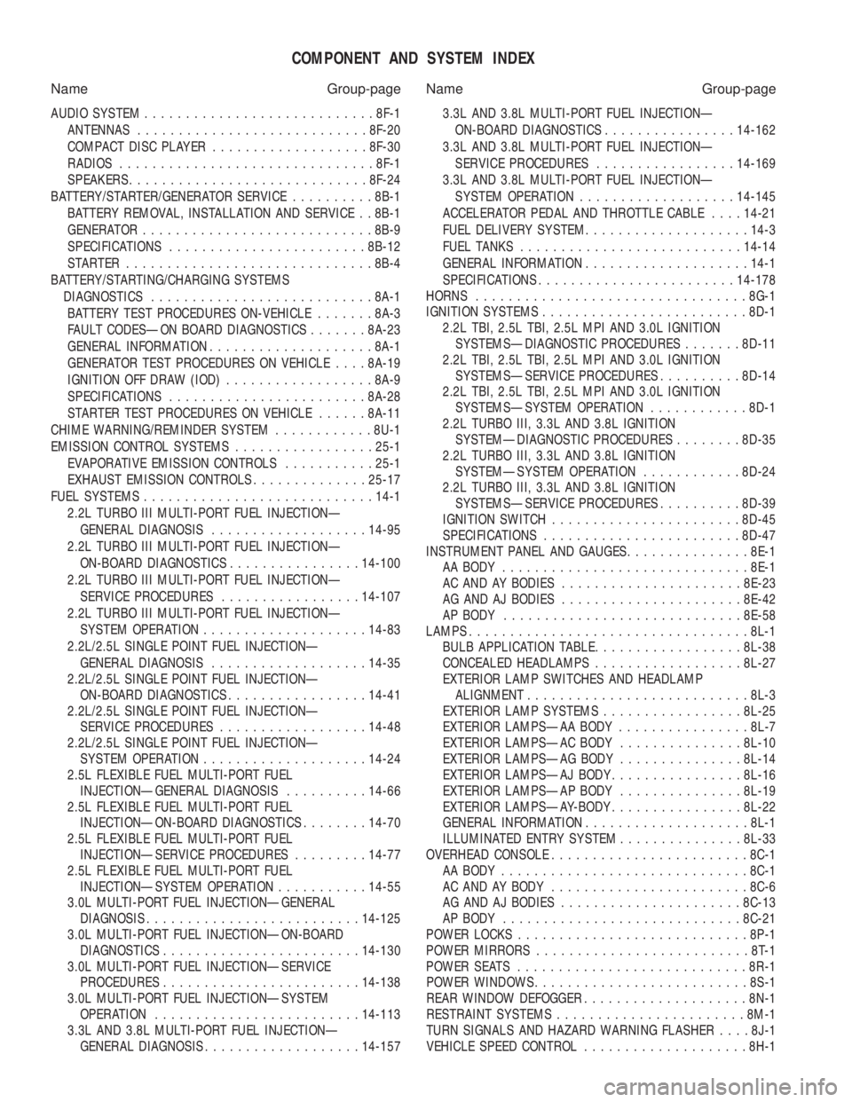
COMPONENT AND SYSTEM INDEX
Name Group-page Name Group-page
AUDIO SYSTEM ............................ 8F-1
ANTENNAS ............................ 8F-20
COMPACT DISC PLAYER ................... 8F-30
RADIOS ............................... 8F-1
SPEAKERS ............................. 8F-24
BATTERY/STARTER/GENERATOR SERVICE ..........8B-1
BATTERY REMOVAL, INSTALLATION AND SERVICE . . 8B-1
GENERATOR ............................ 8B-9
SPECIFICATIONS ........................ 8B-12
STARTER .............................. 8B-4
BATTERY/STARTING/CHARGING SYSTEMS DIAGNOSTICS ........................... 8A-1
BATTERY TEST PROCEDURES ON-VEHICLE .......8A-3
FAULT CODESÐON BOARD DIAGNOSTICS .......8A-23
GENERAL INFORMATION .................... 8A-1
GENERATOR TEST PROCEDURES ON VEHICLE ....8A-19
IGNITION OFF DRAW (IOD) ..................8A-9
SPECIFICATIONS ........................ 8A-28
STARTER TEST PROCEDURES ON VEHICLE ......8A-11
CHIME WARNING/REMINDER SYSTEM ............8U-1
EMISSION CONTROL SYSTEMS .................25-1
EVAPORATIVE EMISSION CONTROLS ...........25-1
EXHAUST EMISSION CONTROLS ..............25-17
FUEL SYSTEMS ............................ 14-1
2.2L TURBO III MULTI-PORT FUEL INJECTIONÐ GENERAL DIAGNOSIS ................... 14-95
2.2L TURBO III MULTI-PORT FUEL INJECTIONÐ ON-BOARD DIAGNOSTICS ................14-100
2.2L TURBO III MULTI-PORT FUEL INJECTIONÐ SERVICE PROCEDURES .................14-107
2.2L TURBO III MULTI-PORT FUEL INJECTIONÐ SYSTEM OPERATION .................... 14-83
2.2L/2.5L SINGLE POINT FUEL INJECTIONÐ GENERAL DIAGNOSIS ................... 14-35
2.2L/2.5L SINGLE POINT FUEL INJECTIONÐ ON-BOARD DIAGNOSTICS .................14-41
2.2L/2.5L SINGLE POINT FUEL INJECTIONÐ SERVICE PROCEDURES .................. 14-48
2.2L/2.5L SINGLE POINT FUEL INJECTIONÐ SYSTEM OPERATION .................... 14-24
2.5L FLEXIBLE FUEL MULTI-PORT FUEL INJECTIONÐGENERAL DIAGNOSIS ..........14-66
2.5L FLEXIBLE FUEL MULTI-PORT FUEL INJECTIONÐON-BOARD DIAGNOSTICS ........14-70
2.5L FLEXIBLE FUEL MULTI-PORT FUEL INJECTIONÐSERVICE PROCEDURES .........14-77
2.5L FLEXIBLE FUEL MULTI-PORT FUEL INJECTIONÐSYSTEM OPERATION ...........14-55
3.0L MULTI-PORT FUEL INJECTIONÐGENERAL DIAGNOSIS .......................... 14-125
3.0L MULTI-PORT FUEL INJECTIONÐON-BOARD DIAGNOSTICS ........................ 14-130
3.0L MULTI-PORT FUEL INJECTIONÐSERVICE PROCEDURES ........................ 14-138
3.0L MULTI-PORT FUEL INJECTIONÐSYSTEM OPERATION ......................... 14-113
3.3L AND 3.8L MULTI-PORT FUEL INJECTIONÐ GENERAL DIAGNOSIS ................... 14-157 3.3L AND 3.8L MULTI-PORT FUEL INJECTIONÐ
ON-BOARD DIAGNOSTICS ................14-162
3.3L AND 3.8L MULTI-PORT FUEL INJECTIONÐ SERVICE PROCEDURES .................14-169
3.3L AND 3.8L MULTI-PORT FUEL INJECTIONÐ SYSTEM OPERATION ................... 14-145
ACCELERATOR PEDAL AND THROTTLE CABLE ....14-21
FUEL DELIVERY SYSTEM .................... 14-3
FUEL TANKS ........................... 14-14
GENERAL INFORMATION .................... 14-1
SPECIFICATIONS ........................ 14-178
HORNS ................................. 8G-1
IGNITION SYSTEMS ......................... 8D-1
2.2L TBI, 2.5L TBI, 2.5L MPI AND 3.0L IGNITION SYSTEMSÐDIAGNOSTIC PROCEDURES .......8D-11
2.2L TBI, 2.5L TBI, 2.5L MPI AND 3.0L IGNITION SYSTEMSÐSERVICE PROCEDURES ..........8D-14
2.2L TBI, 2.5L TBI, 2.5L MPI AND 3.0L IGNITION SYSTEMSÐSYSTEM OPERATION ............8D-1
2.2L TURBO III, 3.3L AND 3.8L IGNITION SYSTEMÐDIAGNOSTIC PROCEDURES ........8D-35
2.2L TURBO III, 3.3L AND 3.8L IGNITION SYSTEMÐSYSTEM OPERATION ............8D-24
2.2L TURBO III, 3.3L AND 3.8L IGNITION SYSTEMSÐSERVICE PROCEDURES ..........8D-39
IGNITION SWITCH ....................... 8D-45
SPECIFICATIONS ........................ 8D-47
INSTRUMENT PANEL AND GAUGES ...............8E-1
AA BODY .............................. 8E-1
AC AND AY BODIES ...................... 8E-23
AG AND AJ BODIES ...................... 8E-42
AP BODY ............................. 8E-58
LAMPS .................................. 8L-1
BULB APPLICATION TABLE ..................8L-38
CONCEALED HEADLAMPS ..................8L-27
EXTERIOR LAMP SWITCHES AND HEADLAMP ALIGNMENT ........................... 8L-3
EXTERIOR LAMP SYSTEMS .................8L-25
EXTERIOR LAMPSÐAA BODY ................8L-7
EXTERIOR LAMPSÐAC BODY ...............8L-10
EXTERIOR LAMPSÐAG BODY ...............8L-14
EXTERIOR LAMPSÐAJ BODY ................8L-16
EXTERIOR LAMPSÐAP BODY ...............8L-19
EXTERIOR LAMPSÐAY-BODY ................8L-22
GENERAL INFORMATION .................... 8L-1
ILLUMINATED ENTRY SYSTEM ...............8L-33
OVERHEAD CONSOLE ........................ 8C-1
AA BODY .............................. 8C-1
AC AND AY BODY ........................ 8C-6
AG AND AJ BODIES ...................... 8C-13
AP BODY ............................. 8C-21
POWER LOCKS ............................ 8P-1
POWER MIRRORS ..........................8T-1
POWER SEATS ............................ 8R-1
POWER WINDOWS .......................... 8S-1
REAR WINDOW DEFOGGER .................... 8N-1
RESTRAINT SYSTEMS ....................... 8M-1
TURN SIGNALS AND HAZARD WARNING FLASHER ....8J-1
VEHICLE SPEED CONTROL .................... 8H-1
Page 40 of 2438

LUBRICANTS AND GREASES
Lubricating grease is rated for quality and usage
by the NLGI. All approved products have the NLGI
symbol on the label. At the bottom NLGI symbol is the usage and qual-
ity identification letters. Wheel bearing lubricant is
identified by the letter ``G''. Chassis lubricant is iden-
tified by the letter ``L''. The letter following the us-
age letter indicates the quality of the lubricant. The
following symbols indicate the highest quality.
FLUID CAPACITIES
Fuel Tank
AP,AG and AJ ......................................53 L (14 gal.)
AA,AC and AY .....................................60 L (16 gal.)
AA-Flexible Fuel ..................................68 L (18 gal.)
Engine Oil
All.........................................................3.8 L (4.5 qts.)
Cooling System
2.2L ......................................................8.5 L (9.0 qts.)
2.5L ......................................................8.5 L (9.0 qts.)
3.0L ......................................................9.0 L (9.5 qts.)
3.3L ......................................................9.0 L (9.5 qts.)
3.8L ......................................................9.0 L (9.5 qts.)
Includes heater and coolant recovery bottle
Automatic Transaxle
Estimated Service Fill
ALL ......................................................3.8 L (4.0 qts.)
Overhaul Fill Capacity with Torque Converter
Empty
3-speed Fleet .......................................8.7 L (9.2 qts.)
3-speed .................................................8.2 L (8.8 qts.)
4-speed Electronic ................................9.4L (9.9 qts.)
Manual Transaxle
All ..........................................................9.4L (9.9 qts.)
Fill to bottom of fill hole.
Power Steering
All ...........................................................75L (1.5 pts.)
PARTS REQUIRING NO LUBRICATION
Many components on a Chrysler Corporation vehi-
cle require no periodic maintenance. Some compo-
nents are sealed and permanently lubricated. Rubber
bushings can deteriorate or limit damping ability if
lubricated. The following list of components require
no lubrication: ²
Air Pump
² Generator Bushings
² Drive Belts
² Drive Belt Idler/Tensioner Pulley
² Front Wheel Bearings
² Rubber Bushings
² Starter Bearings/Bushings
² Suspension Strut Bearings
² Throttle Control Cable
² Throttle Linkage
² Water Pump Bearings
JUMP STARTING PROCEDURE
WARNING: REVIEW ALL SAFETY PRECAUTIONS
AND WARNINGS IN GROUP 8A, BATTERY/START-
ING/CHARGING SYSTEMS DIAGNOSTICS. DO NOT JUMP START A FROZEN BATTERY, PER-
SONAL INJURY CAN RESULT. DO NOT JUMP START WHEN BATTERY INDICA-
TOR DOT IS YELLOW OR BRIGHT COLOR. DO NOT ALLOW JUMPER CABLE CLAMPS TO
TOUCH EACH OTHER WHEN CONNECTED TO A
BOOSTER SOURCE. DO NOT USE OPEN FLAME NEAR BATTERY.
REMOVE METALLIC JEWELRY WORN ON HANDS
OR WRISTS TO AVOID INJURY BY ACCIDENTAL
ARCHING OF BATTERY CURRENT. WHEN USING A HIGH OUTPUT BOOSTING DE-
VICE, DO NOT ALLOW BATTERY VOLTAGE TO EX-
CEED 16 VOLTS. REFER TO INSTRUCTIONS
PROVIDED WITH DEVICE BEING USED.
CAUTION: When using another vehicle as a
booster, do not allow vehicles to touch. Electrical
systems can be damaged on either vehicle.
TO JUMP START A DISABLED VEHICLE:
(1) Raise hood on disabled vehicle and visually in-
spect engine compartment for:
² Battery cable clamp condition, clean if necessary.
² Frozen battery.
² Yellow or bright color test indicator, if equipped.
² Low battery fluid level.
² Generator drive belt condition and tension.
² Fuel fumes or leakage, correct if necessary.
CAUTION: If the cause of starting problem on dis-
abled vehicle is severe, damage to booster vehicle
charging system can result.
(2) When using another vehicle as a booster
source, turn off all accessories, place gear selector in
park or neutral, set park brake and operate engine
at 1200 rpm.
NLGI SYMBOL
0 - 4 LUBRICATION AND MAINTENANCE Ä
Page 41 of 2438

(3) On disabled vehicle, place gear selector in park
or neutral and set park brake. Turn off all accesso-
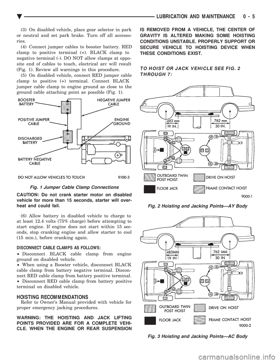
ries. (4) Connect jumper cables to booster battery. RED
clamp to positive terminal (+). BLACK clamp to
negative terminal (-). DO NOT allow clamps at oppo-
site end of cables to touch, electrical arc will result
(Fig. 1). Review all warnings in this procedure. (5) On disabled vehicle, connect RED jumper cable
clamp to positive (+) terminal. Connect BLACK
jumper cable clamp to engine ground as close to the
ground cable attaching point as possible (Fig. 1).
CAUTION: Do not crank starter motor on disabled
vehicle for more than 15 seconds, starter will over-
heat and could fail.
(6) Allow battery in disabled vehicle to charge to
at least 12.4 volts (75% charge) before attempting to
start engine. If engine does not start within 15 sec-
onds, stop cranking engine and allow starter to cool
(15 min.), before cranking again.
DISCONNECT CABLE CLAMPS AS FOLLOWS:
² Disconnect BLACK cable clamp from engine
ground on disabled vehicle.
² When using a Booster vehicle, disconnect BLACK
cable clamp from battery negative terminal. Discon-
nect RED cable clamp from battery positive terminal.
² Disconnect RED cable clamp from battery positive
terminal on disabled vehicle.
HOISTING RECOMMENDATIONS
Refer to Owner's Manual provided with vehicle for
proper emergency jacking procedures.
WARNING: THE HOISTING AND JACK LIFTING
POINTS PROVIDED ARE FOR A COMPLETE VEHI-
CLE. WHEN THE ENGINE OR REAR SUSPENSION IS REMOVED FROM A VEHICLE, THE CENTER OF
GRAVITY IS ALTERED MAKING SOME HOISTING
CONDITIONS UNSTABLE. PROPERLY SUPPORT OR
SECURE VEHICLE TO HOISTING DEVICE WHEN
THESE CONDITIONS EXIST.
TO HOIST OR JACK VEHICLE SEE FIG. 2 THROUGH 7:
Fig. 1 Jumper Cable Clamp Connections
Fig. 2 Hoisting and Jacking PointsÐAY Body
Fig. 3 Hoisting and Jacking PointsÐAC Body
Ä LUBRICATION AND MAINTENANCE 0 - 5
Page 44 of 2438

ENGINE INDEX
page page
Engine Oil Filter .......................... 9
Battery ................................ 15
Crankcase Ventilation System ............... 13
Drive Belts ............................. 14
Emission Control System ................... 14
Engine Air Cleaner ....................... 11
Engine Cooling System .................... 10 Engine Oil
............................... 8
Frequency of Engine Oil and Filter Changes ..... 8
Fuel Filter .............................. 14
Fuel Recommendations .................... 14
Ignition Cables, Distributor Cap, and Rotor ..... 14
Rubber and Plastic Component Inspection ...... 15
Spark Plugs ............................ 14
FREQUENCY OF ENGINE OIL AND FILTER
CHANGES
ENGINE OIL
Road conditions as well as your kind of driving af-
fect the interval at which your oil should be changed.
Check the following to determine if any apply to you:
² Frequent short trip driving less than 8 kilometers
(5 miles)
² Frequent driving in dusty conditions
² Frequent trailer towing
² Extensive idling (such as vehicle operation in stop
and go traffic)
² More than 50% of your driving is at sustained
high speeds during hot weather, above 32ÉC (90ÉF) If any of these apply to you then change your en-
gine oil every 4 800 kilometers (3,000 miles) or 3
months, whichever comes first. If none of these apply to you then change your oil
every 12 000 kilometers (7,500 miles) or 6 months,
whichever comes first. If none of these apply and the vehicle is in com-
mercial type service such as, Police, Taxi or Limou-
sine and principally used for highway driving of 40
kilometers (25 miles) or more between stations, the
engine oil should be changed every 8 000 kilometers
(5,000 miles) or 6 months, whichever comes first.
FLEXIBLE FUEL VEHICLES
Flexible fuel is corrosive and contributes to engine
oil contamination. When flexible fuel is being used,
the engine oil should be changed every 8 000 kilome-
ters (5,000 miles) or 6 months, whichever comes first.
OIL FILTER
The engine oil filter should be replaced with a new
filter at every second oil change.
ENGINE OIL
WARNING: NEW OR USED ENGINE OIL CAN BE IR-
RITATING TO THE SKIN. AVOID PROLONGED OR
REPEATED SKIN CONTACT WITH ENGINE OIL.
CONTAMINANTS IN USED ENGINE OIL, CAUSED
BY INTERNAL COMBUSTION, CAN BE HAZARDOUS TO YOUR HEALTH. THOROUGHLY WASH EX-
POSED SKIN WITH SOAP AND WATER. DO NOT WASH SKIN WITH GASOLINE, DIESEL
FUEL, THINNER, OR SOLVENTS, HEALTH PROB-
LEMS CAN RESULT. DO NOT POLLUTE, DISPOSE OF USED ENGINE
OIL PROPERLY. CONTACT YOUR DEALER OR
GOVERNMENT AGENCY FOR LOCATION OF COL-
LECTION CENTER IN YOUR AREA.
BREAK-IN PERIOD
CAUTION: Wide open throttle operation in low
gears, before engine break-in period is complete,
can damage engine.
On a Chrysler Corporation vehicle an extended
break-in period is not required. Driving speeds of not
over 80-90 km/h (50-55 mph) for the first 100 km (60
miles) is recommended. Hard acceleration and high
engine rpm in lower gears should be avoided.
SELECTING ENGINE OIL
CAUTION: Do not use non-detergent or straight
mineral oil when adding or changing crankcase lu-
bricant. Engine or Turbocharger failure can result.
The factory fill engine oil is a high quality, energy
conserving, crankcase lubricant. The Recommended
SAE Viscosity Grades chart defines the viscosity
grades that must be used based on temperature in
the region where vehicle is operated and optional
equipment.
NON-FLEXIBLE FUEL VEHICLES Chrysler Corporation recommends that Mopar mo-
tor oil, or equivalent, be used when adding or chang-
ing crankcase lubricant. The API symbol (Fig. 1) on
the container indicates the viscosity grade, quality
and fuel economy ratings of the lubricant it contains.
Use ENERGY CONSERVING II motor oil with API
SERVICE SG or SG/CD classification.
0 - 8 LUBRICATION AND MAINTENANCE Ä
Page 51 of 2438

inside of the hood in the engine compartment and
Group 25, Emission Control Systems for proper ser-
vice procedures.
BATTERY
Inspect battery tray, hold down and terminal con-
nections when other under hood service is performed.
For proper diagnostic procedures refer to Group 8A,
Battery/Starting/Charging System Diagnostics. For
service and cleaning procedures refer to Group 8B,
Battery/Starter Service.
RUBBER AND PLASTIC COMPONENT INSPECTION
CAUTION: Plastic hoses or wire harness covers will
melt or deform when exposed to heat from exhaust
system or engine manifolds. Position plastic or rubber components away from
moving parts in engine compartment or under vehi-
cle, or damage will result. Do not allow rubber engine mounts or other com-
ponents to become oil contaminated, repair cause
of oil contamination and clean area. All rubber and plastic components should be in-
spected when engine compartment or under vehicle
service is performed. When evidence of deterioration
exists, replacement is required. To reduce deteriora-
tion of rubber components, Chrysler Corporation rec-
ommends Mopar Foamy Engine Degreaser or
equivalent be used to clean engine compartment of
oil and road grime.
EXHAUST SYSTEM ISOLATOR AND HANGER
The exhaust system should be inspected when un-
der vehicle service is performed. The exhaust system
should not make contact with under body, brake ca-
bles, brake/fuel lines, fuel tank or suspension compo-
nents. Slight cracking in rubber isolator or hanger is
acceptable. Severely cracked or broken rubber compo-
nents must be replaced. For proper service proce-
dures see Group 11, Exhaust System and Intake
Manifold.
Ä LUBRICATION AND MAINTENANCE 0 - 15
Page 120 of 2438

² Air pressure leaks down below 621 kPa (90 psi),
before it remains steady.
² Output pressure builds up to less than 758 kPa
(110 psi) when it stabilizes. If the compressor is allowed to run during this test
until it reaches its maximum output pressure of 1516
kPa (220 psi). The solenoid exhaust valve will act as a pressure relief valve. The resulting leak-down, af-
ter the compressor is shut off, will indicate a false
leak.
SERVICE PROCEDURES
COMPRESSOR ASSEMBLY
REMOVAL
(1) Disconnect negative battery cable.
(2) Raise vehicle, see Hoisting, Group 0.
(3) Remove cover from compressor assembly. Re-
move air hose and electrical connectors (Figs. 1 and
2). (4) Remove compressor assembly mounting bolts
and lower assembly from vehicle. (5) Remove mounting bracket bolts and slide
mounting bracket away from compressor.
INSTALLATION (1) Slide mounting bracket on compressor and in-
stall bolts and tighten to 8 N Im (70 in. lbs.) torque.
(2) Install compressor assembly to frame rail and
tighten bolts to 8 N Im (70 in. lbs.) torque.
(3) Connect air hose and electrical connector to
compressor assembly. (4) Install cover on compressor assembly and
tighten bolts to 8 N Im (70 in. lbs.) torque.
(5) Lower vehicle and connect negative battery ca-
ble. (6) Check operation of the system.
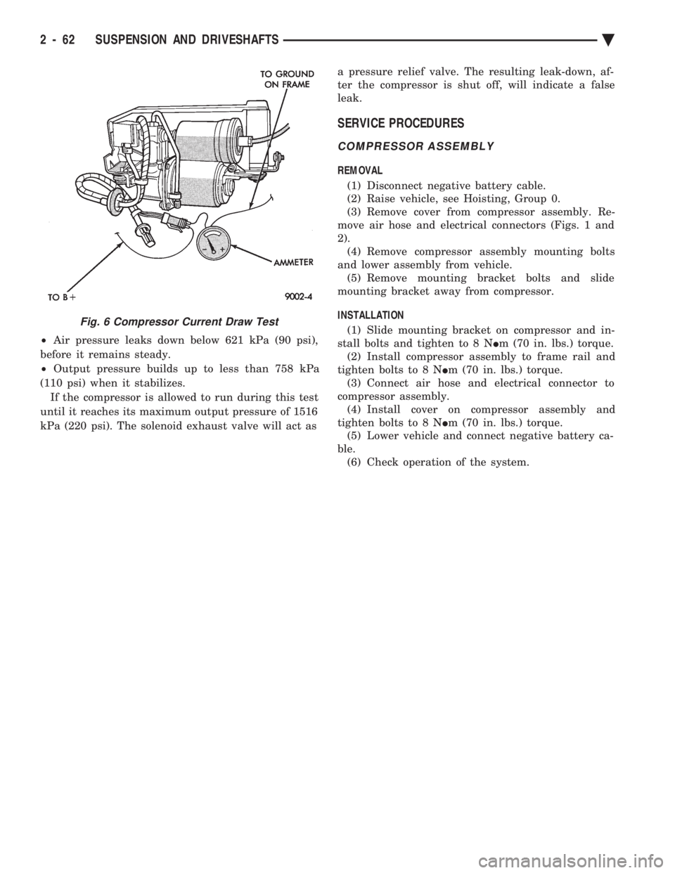
Fig. 6 Compressor Current Draw Test
2 - 62 SUSPENSION AND DRIVESHAFTS Ä
Page 130 of 2438

CONTROL MODULE
REMOVAL
(1) Disconnect negative battery cable.
(2) Remove right side trunk trim panel.
(3) Remove electrical connectors from control mod-
ule and relay (Fig. 9). (4) Remove control module mounting screws and
remove assembly.
INSTALLATION
(1) Install relay on the control module mounting
bracket (if required). (2) Place control module in mounting position.
(3) Install mounting screws and tighten to 2-3 N Im
(19-29 in. lbs.). (4) Install control module and relay wiring connec-
tors (Fig. 9). (5) Install right side trunk trim panel.
(6) Connect negative battery cable.
COMPRESSOR RELAY
REMOVAL
(1) Remove right side trunk trim panel.
(2) Remove electrical connector from relay.
(3) Remove relay from control module mounting
bracket by prying out on locating clip (Fig. 10).
INSTALLATION
(1) Push relay onto bracket (relay will Lock into
position). (2) Install electrical connector.
(3) Install trim panel.
RIGHT SHOCK ABSORBER (WITH HEIGHT
SENSOR)
REMOVAL
(1) Disconnect negative battery cable.
(2) Raise vehicle, see Hoisting, Group 0.
(3) Remove tire assembly.
(4) Disconnect height sensor connector, located on
right rear frame rail. (5) Remove both air lines connected to shock ab-
sorber ports. (6) Remove shock, see Shock Absorbers, Removal.
INSTALLATION
(1) Install shock assembly, see Shock Absorbers,
Installation. (2) Route height sensor wire through clip on shock
bracket, then tie strap to fuel filler tube. (3) Snap height sensor connector into underbody
harness connector. (4) Insert air lines.
(5) Install wheel/tire assembly.
Fig. 9 Control Module and Relay Wiring
Fig. 10 Control Module Connector
2 - 72 SUSPENSION AND DRIVESHAFTS Ä