1993 CHEVROLET DYNASTY battery
[x] Cancel search: batteryPage 243 of 2438
DRIVE-OFF CYCLE
The DRIVE-OFF CYCLE takes place when the ve-
hicle reaches about 3 miles per hour the first time af-
ter an ignition reset. During this test, the modulator
solenoid valves are activated briefly to test their
function. The DRIVE-OFF CYCLE will be bypassed
if you drive-off with the service brake pedal de-
pressed.
LATCHING VERSUS NON-LATCHING FAULTS
Some faults detected by the (CAB) are latching.
The fault is latched and (ABS) function is disabled
until the ignition switch is reset (turned OFF/ON).
Thus (ABS) function is disabled even if the original
fault has disappeared during the ignition cycle in
which it occurred. Other faults are non-latching; any
warning lights that are turned on are only on as long
as the fault condition exists. As soon as the condition
goes away. The Amber Anti-Lock Warning Light is
turned off. Although a fault code will be set in most
cases. (Example:low accumulator fault will not be
stored for a time of 2 minutes after the fault is de-
tected).
BENDIX ABS SYSTEMS DIAGNOSTICS
The Bendix Anti-Lock 10 Brake System diagnos-
tics. Beyond the basic mechanical diagnostics, sys-
tems and components covered earlier in this section,
is accomplished by using the DRB II diagnostic
tester. See testing procedures outlined in the Bendix
Anti-Lock 10 Diagnostics Manual for the 1993 M.Y. Please reference the above mentioned manual. For
any further diagnostic service procedures that are re-
quired on the Bendix Anti-Lock 10 Brake System, re-
quiring the use of the DRB II diagnostic tester.
ON CAR HYDRAULIC ABS COMPONENT SERVICE
WARNING: FAILURE TO FULLY DE-PRESSURIZE
THE HYDRAULIC ACCUMULATOR BEFORE PER-
FORMING HYDRAULIC SYSTEM SERVICE OPERA-
TIONS. COULD RESULT IN INJURY TO SERVICE
PERSONNEL AND OR DAMAGE TO PAINTED SUR-
FACES. SEE SECTION 2 FOR ADDITIONAL WARN-
INGS AND CAUTIONS.
GENERAL SERVICE PRECAUTIONS
The following are general precautions that should
be observed when servicing the Anti-Lock Brake Sys-
tem and/or other vehicle systems. Failure to observe
these precautions may result in Anti-Lock brake sys-
tem damage. If welding work is to be performed on the vehicle,
using an electric arc welder, the (CAB) connector
should be disconnected during the welding operation. The (CAB) or hydraulic assembly connector should
never be connected or disconnected with the ignition
switch in the ONposition.
Many components of the Anti-Lock brake system are
not serviceable and must be replaced as an assembly.
Do not attempt to disassemble any component
that is not designed to be a serviced component.
DE-PRESSURIZING HYDRAULIC ACCUMULA- TOR
The pump/motor assembly will keep the hydraulic
accumulator charged to approximately 11,032 and
13,790 kPa (1600 and 2000 psi) any time that the
ignition is in the ON position. The pump/motor assem-
bly cannot run if the ignition is off or if either battery
cable is disconnected. Unless otherwise specified, the hydraulic accumula-
tor should be de-pressurized before disassembling any
portion of the hydraulic system. The following proce-
dure should be used to relieve the pressure in the
hydraulic accumulator: (1) With ignition off, or either battery cable discon-
nected, pump the brake pedal a minimum of 40 times,
using approximately 222 N (50 lbs.) pedal force. A
noticeable change in pedal feel will occur, when the
accumulator is discharged. (2) When a definite increase in pedal effort is felt,
pump pedal a few additional times. This will insure
removal of all hydraulic pressure from the brake sys-
tem.
CHECKING BRAKE FLUID LEVEL
CAUTION: Use only brake fluid conforming to DOT 3
specifications such as Mopar Tor Equivalent. Do not
use any fluid in the brake hydraulic system, which
contains a petroleum base. Do not use a container
which has been used for petroleum based fluids or a
container that is wet with water. Petroleum based
fluids will cause swelling and distortion of rubber
parts in the hydraulic brake system and water will mix
with brake fluid, lowering the fluid boiling point. Keep
all brake fluid containers tightly capped to prevent
contamination.
The hydraulic assembly is equipped with a plastic
fluid reservoir, with a filter/strainer located in the filler
neck of each reservoir section. The Anti-Lock brake system requires that the hy-
draulic accumulator be de-pressurized when checking
the fluid level. To check the brake fluid level, the
following procedure should be used: (1) With the ignition off, de-pressurize the hydraulic
accumulator by applying the brake pedal approxi-
mately 40 times, using a pedal force of approximately
220 N (50 lbs.). A noticeable change in pedal feel will
occur when the accumulator is de-
Ä ANTI-LOCK 10 BRAKE SYSTEM 5 - 93
Page 266 of 2438
If the vehicle is not set in motion within 3 minutes
from the time the ignition switch is set in the on po-
sition. The solenoid test is bypassed but the pump/
motor is activated briefly to verify that it is
operating correctly.
WARNING SYSTEMS OPERATION
The ABS system uses an Amber Anti-Lock Warn-
ing Lamp, located in the instrument cluster. The
purpose of the warning lamp is discussed in detail
below. The Amber Anti-Lock Warning Light will turn on
when the (CAB) detects a condition which results in
a shutdown of the Anti-Lock function. The Amber
Anti-Lock Warning Lamp is normally on until the
(CAB) completes its self tests and turns the lamp off
(approximately 1-2 seconds). When the Amber Anti-
Lock Warning Light is on only the Anti-Lock func-
tion of the brake system if affected. The standard
brake system and the ability to stop the car will not
be affected when only the Amber Anti-Lock Warning
Light is on.
NORMAL OPERATION OF WARNING LAMP
With the ignition in the Crank position, the Red
Brake Warning Lamp will turn on as a bulb check.
The Amber Anti-Lock Warning Lamp will stay on for
1-2 seconds then turn off. Once verification of the self
diagnosis is completed.
ANTI-LOCK BRAKE SYSTEM COMPONENTS
The following is a detailed description of the Anti-
Lock Brake System components. For information on
servicing the Four Wheel Disk Brake System, see the
standard Brake section of this Service Manual.
MODULATOR ASSEMBLY
WARNING: THE ONLY PART OF THE MODULATOR
ASSEMBLY THAT IS A SERVICEABLE COMPONENT
IS THE DELTA P SWITCH. THE REMAINING COM-
PONENTS OF THE MODULATOR ASSEMBLY ARE
NOT SERVICEABLE ITEMS. NO ATTEMPT SHOULD
BE MADE TO REMOVE OR SERVICE ANY OTHER
PARTS OF THE MODULATOR ASSEMBLY.
The Modulator Assembly (Fig. 1) is located under
the battery tray and is covered with an acid shield.
The Modulator Assembly contains the following com-
ponents for controlling the Anti-Lock braking sys-
tem. 2 Isolation Valves, 4 Build/Decay Valves, 4
Shuttle Orifices, 2 Fluid Sumps, 2 Accumulators, a
Pump/Motor and a Pressure Differential Valve/
Switch. Also attached to the Modulator Assembly are
4 brake tubes which are connected to an 8 way con-
nector block. The connector block is mounted to the
left frame rail below the master cylinder in the same location as the non ABS equipped combination valve.
The wheel brake lines are attached to the system via
the connector block.
ISOLATION VALVES
The Isolation Valves are used to isolate the master
cylinder from the rest of the brake hydraulic circuit
during an Anti-Lock stop. Two Isolation Valves are
used, one for the primary circuit and one for the sec-
ondary circuit. The Isolation Valves are spring
loaded in the released position. In the released posi-
tion the Isolation Valves provide a fluid path from
the master cylinder outputs to the wheel brakes via
the Build/Decay valves. When actuated it provides a
fluid path from the accumulator (which was charged
by the Pump/Motor during ABS operation) to the
Build/Decay valves through the Shuttle Orifices.
BUILD/DECAY VALVES
There are 4 Build/Decay valves, one for each
wheel. In the released position they provide a fluid
path from the wheel brakes to the Isolation Valve
through the shuttle orifices. In the actuated (decay)
position, they provide a fluid path from the wheel
brakes to the sump. The Build/Decay valves are
spring loaded in the released (build) position.
SHUTTLE ORIFICE
There are 4 Shuttle Orifice Valves, one for each
wheel. The Shuttle Orifice Valve is a hydraulically
actuated valve which shuttles when the Build/Decay
valve is actuated. Actuating of the Build/Decay valve
causes a pressure differential to be created across the
Shuttle Orifice Valve. This acts like placing an ori-
fice (restriction) in the line between the Isolation
Valve and the Build/Decay Valve. This restriction
provides a controlled build rate to each wheel brake
during an Anti-Lock stop. The Shuttle Orifice Valve
will remain in the orificed position until the ABS cy-
cle is complete. When the ABS cycle has been com-
pleted the Isolation and Build/Decay valves will
return to their released position which will equalize
the pressure across the Shuttle Orifice Valves. When
the pressure equalizes, the spring loaded Shuttle Or-
ifice valves will return to the unrestricted position.
FLUID SUMPS
There are two Fluid Sumps in the Hydraulic As-
sembly, one each for the primary and secondary hy-
draulic circuits. The Fluid Sumps store the brake
fluid that is decayed from the wheel brakes during
ABS cycle. This fluid is then pumped to an accumu-
lator and/or the hydraulic system in order to provide
build pressure. The typical pressure in the sumps is
50 psi, During ABS operation only.
5 - 116 ANTI-LOCK 6 BRAKE SYSTEM Ä
Page 274 of 2438

In order to effectively diagnose an Anti-Lock Brake
System (ABS) condition. It is important to read Anti-
Lock Brake System Description. And to follow the
diagnostic procedures outlined in this section. Many conditions that generate customer complaints
may be normal operating conditions, but are judged to
be a problem due to not being familiar with the ABS
system. These conditions can be recognized without
performing extensive diagnostic work. Given adequate
understanding of the operating principles and perfor-
mance characteristics of the ABS system. See Section 1
of this manual to familiarize yourself with the operat-
ing principles of the ABS system.
DEFINITIONS
Several abbreviations are used in this manual. They
are presented here for reference.
² CABÐController Anti-Lock Brake
² ABSÐAnti-Lock Brake System
² PSIÐPounds per Square Inch (pressure)
² WSSÐWheel Speed Sensor
ABS COMPUTER SYSTEM SERVICE PRECAUTIONS
The ABS system uses an electronic control module,
the (CAB). This module is designed to withstand nor-
mal current draws associated with vehicle operation.
However care must be taken to avoid overloading the
(CAB) circuits. In testing for open or short circuits,
do not ground or apply voltage to any of the
circuits unless instructed to do so by the appro-
priate diagnostic procedure. These circuits should
only be tested using a high impedance multi-meter,
special tools or the DRB II tester as described in this
section. Power should never be removed or applied to
any control module with the ignition in the ON posi-
tion. Before removing or connecting battery cables,
fuses, or connectors, always turn the ignition to the
OFF position.
ABS GENERAL SERVICE PRECAUTIONS
TEST DRIVING ABS COMPLAINT VEHICLES
Most ABS complaints will require a test drive as a
part of the diagnostic procedure. The purpose of the
test drive is to duplicate the condition. Remember conditions that result in the turn-
ing on of the Red Brake Warning Lamp may
indicate reduced braking ability. The following
procedure should be used to test drive an ABS
complaint vehicle. Before test driving a brake complaint vehicle, note
whether the Red or Amber Brake Warning Lamp is
turned on. If it is the Red Brake Warning Lamp, refer
to the standard brake, Control Valves Section in the
brake group of this manual. If the Amber Anti-Lock
Warning light was/is on, read record and erase the
fault. While the Amber ABS Warning Lamp is on the
ABS system is not functional. When the Am- ber Anti-Lock Warning Lamp is on only the Anti-Lock
function of the brake system if affected. The standard
brake system and the ability to stop the car is not be
affected if only the Amber Anti-Lock Warning Lamp is
on. (1) Turn the key to the off position and then back to
the on position. Note whether the Amber ABS Warning
Lamp continues to stay on. If it does refer to the 1993
M.Y. Bendix Anti-Lock 6 Diagnostic Manual for the
required test procedures. (2) If the Amber ABS Warning Lamp goes out, shift
into gear and drive the car to a speed of 5 mph to
complete the ABS start up cycle. If at this time the
Amber ABS Warning Lamp goes on refer to the Bendix
Anti-Lock 6 Diagnostic Manual. (3) If the Amber ABS Warning Lamp remains OUT,
drive the vehicle a short distance. During this test
drive be sure that the vehicle achieves at least 25 mph.
Brake to at least one complete stop and again acceler-
ate to 25 mph. (4) If a functional problem with the A.B.S. system is
determined while test driving a vehicle. Refer to the
Bendix Anti-Lock 6 Diagnostics Manual for required
test procedures and proper use of the DRB II tester.
ABS BRAKE SYSTEM ON VEHICLE SERVICE
The following are general precautions which
should be observed when servicing and diagnos-
ing the ABS system and/or other vehicle systems.
Failure to observe these precautions may result
in ABS system damage. (1) If welding work is to be performed on a vehicle
using an arc welder, the (CAB) should be disconnected
before the welding operation begins. (2) The (CAB) and modulator assembly 10 way con-
nector should never be connected or disconnected with
the ignition in the on position. (3) Some components of the ABS system are not
serviced separately and must be serviced as complete
assemblies. Do not disassemble any component which
is designated as non-serviceable.
CAUTION: Brake fluid will damage painted surfaces.
If brake fluid is spilled on any painted surfaces, wash
off with water immediately.
WHEEL SPEED SENSOR CABLES
Proper installation of the Wheel Speed Sensor Cables
is critical to continued system operation. Be sure that
cables are installed, routed and clipped properly. Fail-
ure to install speed sensor cables as shown in the on
car service section of this manual. May result in
contact with moving parts or over extension of cables,
resulting in component failure and an open circuit.
5 - 124 ANTI-LOCK 6 BRAKE SYSTEM Ä
Page 276 of 2438
As soon as the condition goes away, the Anti-Lock
Warning Light is turned off. Although a fault code
will be set in most cases.
BENDIX ABS SYSTEMS DIAGNOSTICS
Bendix Anti-Lock 6 Brake System Diagnostics, be-
yond basic mechanical diagnostics, covered earlier in
this section. Are accomplished by using the DRB II
scan tool. See testing procedures outlined in the Ben-
dix Anti-Lock 6 Diagnostics Manual for the 1992
M.Y. vehicles. Please refer to the above mentioned manual for
any further electronic diagnostics and service proce-
dures that are required on the Bendix Anti-Lock 6
Brake System.
ON-CAR ABS BRAKE SYSTEM SERVICE
GENERAL SERVICE PRECAUTIONS
The following are general cautions which should be
observed when servicing the Anti-Lock brake system
and/or other vehicle systems. Failure to observe
these precautions may result in Anti-Lock Brake
System component damage. If welding work is to be performed on the vehicle,
using an electric arc welder, the (CAB) connector
should be disconnected during the welding operation. The (CAB) connector should never be connected or
disconnected with the ignition switch in the ON po-
sition. Many components of the Anti-Lock Brake System
are not serviceable and must be replaced as an as-
sembly. Do not disassemble any component which is
not designed to be serviced.
CHECKING BRAKE FLUID LEVEL
CAUTION: Only use brake fluid conforming to DOT
3 specifications, such as Mopar or Equivalent. Do
not use any fluid which contains a petroleum base.
Do not use a container which has been used for pe-
troleum based fluids or a container which is wet
with water. Petroleum based fluids will cause swell-
ing and distortion of rubber parts in the hydraulic
brake system. Water will mix with brake fluid, low-
ering the fluid boiling point. Keep all brake fluid
containers capped to prevent contamination. Re-
move the front cap of the master cylinder reservoir
and fill to the bottom of the split ring.
For the specific procedure for the inspection of
brake fluid level and adding of brake to the reser-
voir. Refer to the Service Adjustments Section in this
group of the service manual.
BLEEDING BENDIX ANTI-LOCK 6 BRAKE SYSTEM
The Anti-Lock Brake System must be bled anytime
air is permitted to enter the hydraulic system, due to
disconnection of brake lines, hoses of components. If the Modulator Assembly is removed from the ve-
hicle, both the Base Brake System and the Anti-Lock
Brake System must be bled using the appropriate
procedures. It is important to note that excessive air
in the brake system will cause a soft or spongy feel-
ing brake pedal. During bleeding operations, be sure that the brake
fluid level remains close to the FULL level in the
reservoir. Check the fluid level periodically during
the bleeding procedure and add DOT 3 brake fluid as
required. The Bendix Anti-Lock 6 Brake System must be
bled as two independent braking systems. The non
ABS portion of the brake system is to be bled the
same as any non ABS system. Refer to the Service
Adjustments section in this manual for the proper
bleeding procedure to be used. This brake system can
be either pressure bled or manually bled. The Anti-Lock portion of brake system MUST be
bled separately. This bleeding procedure requires the
use of the DRB II Diagnostic tester and the bleeding
sequence procedure outlined below.
ABS BLEEDING PROCEDURE (FIG. 1)
(1) Assemble and install all brake system compo-
nents on vehicle making sure all hydraulic fluid
lines are installed and properly torqued. (2) Bleed the base brake system. Using the stan-
dard pressure or manual bleeding procedure as out-
lined in the Service Adjustments section of this
service manual. To perform the bleeding procedure on the ABS
unit. The battery and acid shield must be removed
from the vehicle. Reconnect the vehicles battery, to
the vehicles positive and negative battery cables us-
ing jumper cables. This is necessary to allow access
to the 4 bleeder screws located on the top of the Mod-
ulator assembly. (3) Connect the DRB II Diagnostics Tester to the
diagnostics connector. Located behind the Fuse Panel
access cover on the lower section of the dash panel to
the left of the steering column. (It is a blue 6 way
connector). (4) Using the DRB II check to make sure the
(CAB) does not have any fault codes stored. If it does
remove them using the DRB II.
5 - 126 ANTI-LOCK 6 BRAKE SYSTEM Ä
Page 278 of 2438
(6) Repeat steps 2 through 5 until a clear air free
flow of brake fluid is coming out of the Primary Ac-
cumulator bleeder screw. (7) Next select and actuate the RF Build/Decay
Valve. Again repeat steps 2 through 5 until a clean
air free flow of brake fluid is coming out of the Pri-
mary Accumulator bleeder screw.
4 SECONDARY ACCUMULATOR (1) Put a bleeder tube on the Secondary Accumu-
lator bleeder screw. (Fig. 1) (2) Use a pressure bleeder, or have an assistant,
apply light and constant pressure on the brake pedal.
Loosen the Secondary Accumulator bleeder screw
(Fig. 1). (3) Using the DRB II select the Actuate Valves
test mode. Then actuate the LF/RR Isolation Valve. (4) Bleed the Secondary Accumulator. Until a clear
air free flow of brake fluid is evident in the clear
hose and no air bubbles appear in the container, or
the brake pedal bottoms. (5) Tighten the bleeder screw and release the
brake pedal. (6) Repeat steps 2 through 5 until a clear air free
flow of brake fluid is coming out of the Secondary
Accumulator bleeder screw. (7) Next select and actuate the LF Build/Decay
Valve. Again repeat steps 2 through 5 until a clean
air free flow of brake fluid is coming out of the Pri-
mary Accumulator bleeder screw.PUMP/MOTOR SERVICE
On the Bendix Anti-Lock 6 Brake System the
Pump/Motor assembly can only be serviced as part of
Modulator Assembly.
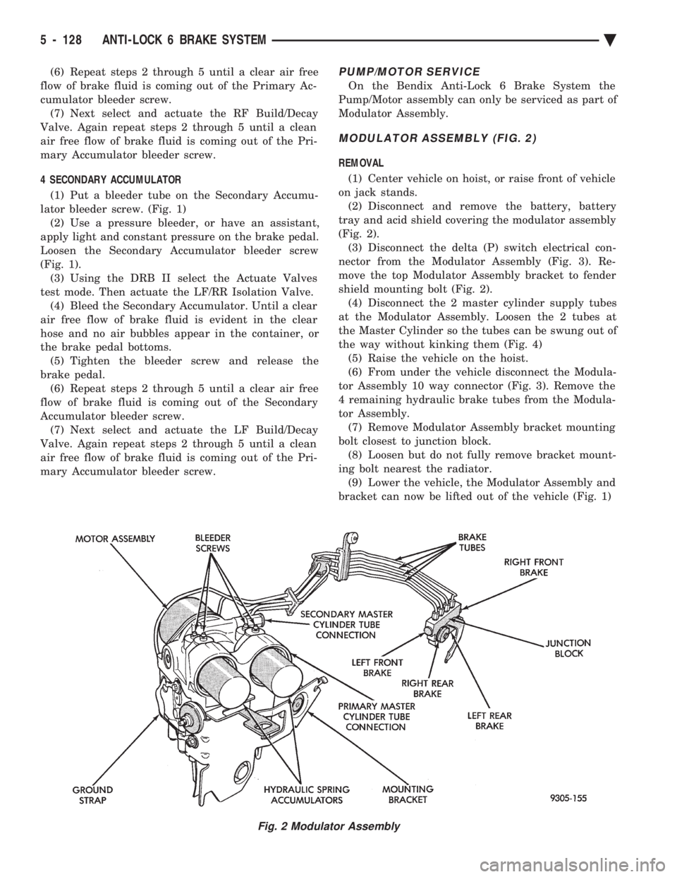
MODULATOR ASSEMBLY (FIG. 2)
REMOVAL
(1) Center vehicle on hoist, or raise front of vehicle
on jack stands. (2) Disconnect and remove the battery, battery
tray and acid shield covering the modulator assembly
(Fig. 2). (3) Disconnect the delta (P) switch electrical con-
nector from the Modulator Assembly (Fig. 3). Re-
move the top Modulator Assembly bracket to fender
shield mounting bolt (Fig. 2). (4) Disconnect the 2 master cylinder supply tubes
at the Modulator Assembly. Loosen the 2 tubes at
the Master Cylinder so the tubes can be swung out of
the way without kinking them (Fig. 4) (5) Raise the vehicle on the hoist.
(6) From under the vehicle disconnect the Modula-
tor Assembly 10 way connector (Fig. 3). Remove the
4 remaining hydraulic brake tubes from the Modula-
tor Assembly. (7) Remove Modulator Assembly bracket mounting
bolt closest to junction block. (8) Loosen but do not fully remove bracket mount-
ing bolt nearest the radiator. (9) Lower the vehicle, the Modulator Assembly and
bracket can now be lifted out of the vehicle (Fig. 1)
Fig. 2 Modulator Assembly
5 - 128 ANTI-LOCK 6 BRAKE SYSTEM Ä
Page 280 of 2438
junction block. Torque both lower mounting bracket
bolts to 28 N Im (250 in. lbs.)
(4) Reinstall the 4 hydraulic brake tubes to the
Modulator Assembly and torque the fittings to 16
N Im (145 in. lbs.).
(5) Reconnect the 10 way Modulator assembly con-
nector, and the delta P switch connector. (6) Lower the vehicle and install the 2 master cyl-
inder supply tubes to the Modulator Assembly.
Torque the Modulator Assembly fittings and the
master cylinder fittings to 16 N Im (145 in.lbs.).
(7) Torque the Modulator to fender splash shield
attaching bolt to 28 N Im (250 in. lbs.)
(8) Bleed the brake system. Refer to the Bleeding
Bendix Anti 6 Brake System in this section of the
manual for proper bleeding procedure. (9) Reinstall the acid shield and battery tray. Re-
install battery and connect battery cables.
MASTER CYLINDER AND POWER BOOSTER
REMOVAL AND INSTALLATION
If the Master Cylinder or the Power Booster need
to be serviced or replaced. Refer to Master Cylinder
or Power Brake Service section in this group of the
service manual. After servicing the Master Cylinder. Refer back to
this section of the service manual. For the appropri-
ate procedure and sequence, used to bleed the base
and ABS portion of the brake system
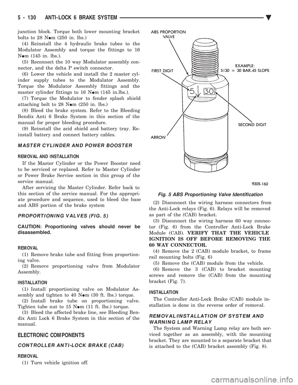
PROPORTIONING VALVES (FIG. 5)
CAUTION: Proportioning valves should never be
disassembled.
REMOVAL (1) Remove brake tube and fitting from proportion-
ing valve. (2) Remove proportioning valve from Modulator
Assembly.
INSTALLATION (1) Install proportioning valve on Modulator As-
sembly and tighten to 40 N Im (30 ft. lbs.) torque.
(2) Install brake tube on proportioning valve.
Tighten tube nut to 15 N Im (11 ft. lbs.) torque.
(3) Bleed the affected brake line, see Bleeding Ben-
dix Anti Lock 6 Brake System in this section of the
manual.
ELECTRONIC COMPONENTS
CONTROLLER ANTI-LOCK BRAKE (CAB)
REMOVAL
(1) Turn vehicle ignition off. (2) Disconnect the wiring harness connectors from
the Anti-Lock relays (Fig. 6). Relays will be removed
as part of the (CAB) bracket. (3) Disconnect the wiring harness 60 way connec-
tor (Fig. 6) from the Controller Anti-Lock Brake
Module (CAB). VERIFY THAT THE VEHICLE
IGNITION IS OFF BEFORE REMOVING THE
60 WAY CONNECTOR. (4) Remove the 2 (CAB) module bracket, to frame
rail mounting bolts (Fig. 6) (5) Remove the (CAB) module from the vehicle.
(6) Remove the 3 (CAB) to bracket mounting
screws and remove the (CAB) from the mounting
bracket (Fig. 7).
INSTALLATION
The Controller Anti-Lock Brake (CAB) module in-
stallation is done in the reverse order of removal.
REMOVAL/INSTALLATION OF SYSTEM AND WARNING LAMP RELAY
The System and Warning Lamp relay are both ser-
viced together as an assembly, with the mounting
bracket. They are mounted to a separate bracket that
is attached to the (CAB) bracket assembly (Fig. 8).
Fig. 5 ABS Proportioning Valve Identification
5 - 130 ANTI-LOCK 6 BRAKE SYSTEM Ä
Page 302 of 2438

(2) The voltage output from each of the wheel
speed sensors is verified to be within the correct op-
erating range. If a vehicle is not set in motion within 3 minutes
from the time the ignition switch is turned to the on
position. The solenoid valve test is bypassed but the
pump/motor is activated briefly to verify that it is op-
erating correctly.
WARNING SYSTEMS OPERATION
The ABS system uses an Amber Antilock Warning
Lamp, located in the instrument cluster. The purpose
of the warning lamp is discussed in detail below. The Amber Antilock Warning Light will turn on
whenever the CAB detects a condition which results
in a shutdown of the Antilock brake system. The
Amber Antilock Warning Lamp is normally on until
the CAB completes its self tests and turns the lamp
off (approximately 1-2 seconds). When the Amber
Antilock Warning Light is on, only the Antilock
brake function of the brake system if affected. The
standard brake system and the ability to stop the car
will not be affected when only the Amber Antilock
Warning Light is on.
NORMAL OPERATION OF WARNING LAMP
With ignition key turned to the Crank position, the
Red Brake Warning Lamp and Amber Antilock
Warning Lamp will turn on as a bulb check. The
Amber Antilock Warning Lamp will stay on for 1-2
seconds then turn off, once verification of Antilock
Brake System self diagnosis is completed.
ANTILOCK BRAKE SYSTEM COMPONENTS
The following is a detailed description of the Ben-
dix Antilock 4 Brake System components. For infor-
mation on servicing the Four Wheel Disc Brake
System, see the standard Brake section in the Front
Wheel Drive Car, chassis service manual.
MODULATOR ASSEMBLY
WARNING: THE ONLY COMPONENTS OF THE
MODULATOR ASSSEMBLY THAT ARE SERVICE-
ABLE, ARE THE 2 PROPORTIONING VALVES,
BLEED SCREWS AND THREAD SAVERS. THE RE-
MAINING COMPONENTS OF THE MODULATOR AS-
SEMBLY ARE NOT INTENDED TO BE
SERVICEABLE ITEMS. NO ATTEMPT SHOULD BE
MADE TO REMOVE OR SERVICE ANY OTHER COM-
PONENTS OF THE MODEULATOR ASSEMBLY.
The Modulator Assembly (Fig. 1) is located under
the battery tray and is covered with an acid shield.
The Modulator Assembly contains the following com-
ponents for controlling the Antilock brake system. 4
Build/Decay Valves, 4 Shuttle Orifices, 2 Fluid
Sumps, 2 Accumulators, and a Pump/Motor assem- bly. Also attached to the Modulator Assembly are 6
brake tubes which are connected to a 12 way junc-
tion block. The junction block (Fig. 2) is mounted to
the left frame rail below the master cylinder in the
same location as the non ABS equipped combination
valve. The wheel brake lines are attached to the sys-
tem via the connector block.BUILD/DECAY VALVES
There are 4 Build/Decay valves, one for each
wheel. In the released position they provide a fluid
path direct to the wheel brakes. In the actuated (de-
cay) position, they provide a fluid path from the
wheel brakes to the sump. The Build/Decay valves
are spring loaded in the released (build) position.
SHUTTLE ORIFICE
There are 4 Shuttle Orifice Valves, one for each
wheel. The Shuttle Orifice Valve is a hydraulically
actuated valve which shuttles when the Build/Decay
valve is actuated. Actuating of the Build/Decay valve
causes a pressure differential to be created across the
Shuttle Orifice Valve. This acts like placing an ori-
Fig. 1 Modulator Assembly
Fig. 2 Antilock Brake Junction Block
5 - 16 ANTILOCK 4 BRAKE SYSTEM Ä
Page 309 of 2438

earlier in this service manual supplement. Then follow
the diagnostic procedures outlined in this section. Many conditions that generate customer complaints
may be normal operating conditions, but are judged to
be a problem due to not being familiar with the ABS
system. These conditions can be recognized without
performing extensive diagnostic work, given adequate
understanding of the operating principles and perfor-
mance characteristics of the ABS system.
DEFINITIONS
Several abbreviations are used in this manual. They
are presented here for reference.
² CABÐController Antilock Brake
² ABSÐAntilock Brake System
² PSIÐPounds per Square Inch (pressure)
² WSSÐWheel Speed Sensor
² ACÐAlternating Current
ABS COMPUTER SYSTEM SERVICE PRECAUTIONS
The ABS system uses an electronic control module,
the CAB. This module is designed to withstand normal
current draws associated with vehicle operation. How-
ever care must be taken to avoid overloading the CAB
circuits. In testing for open or short circuits, do
not ground or apply voltage to any of the circuits
unless instructed to do so by the appropriate
diagnostic procedure. These circuits should only be
tested using a high impedance multi-meter, special
tools or the DRB II tester as described in this section.
Power should never be removed or applied to any
control module with the ignition in the ON position.
Before removing or connecting battery cables, fuses, or
connectors, always turn the ignition to the OFF posi-
tion.
ABS GENERAL SERVICE PRECAUTIONS
TEST DRIVING ABS COMPLAINT VEHICLES
Most ABS complaints will require a test drive as a
part of the diagnostic procedure. The purpose of the
test drive is to duplicate the condition. Remember conditions that result in the turn-
ing on of the Red Brake Warning Lamp may
indicate reduced braking ability. The following
procedure should be used to test drive an ABS
complaint vehicle. Before test driving a brake complaint vehicle, note
whether the Red or Amber Brake Warning Lamp is
turned on. If the Red Brake Warning Lamp, is
turned on, refer to the base brake Control Valves
Section in the Front Wheel Drive, chassis service
manual. If the Amber Antilock Warning light was or
is on, read record and erase the faults. While the
Amber ABS Warning Lamp is on the ABS system is
not functional. The standard brake system and abil- ity to stop the car is not affected, if only the Amber
Antilock Warning Lamp is on.
(1) Turn ignition key to the off position and then
back to the on position. Note whether the Amber ABS
Warning Lamp continues to stay on. If it does refer to
the 1994 Bendix Antilock 4 Brake System Diagnostic
Manual for the required diagnostic test procedures. (2) If the Amber ABS Warning Lamp goes out, shift
vehicle into gear and drive car to a speed of 5 mph to
complete the ABS drive-off cycle. If at this time, the
Amber ABS Warning Lamp goes on refer to the 1994
Bendix Antilock 4 Brake System Diagnostic Manual. (3) If the Amber ABS Warning Lamp remains OUT,
continue to drive the vehicle a short distance. During
this test drive be sure that the vehicle achieves at least
25 mph. Brake to at least one complete stop and again
accelerate to 25 mph. (4) If a functional problem with the ABS system is
determined while test driving a vehicle. Refer to the
Bendix Antilock 4 Brake System Diagnostics Manual
for required diagnostic test procedures and proper use
of the DRB II tester.
ABS BRAKE SYSTEM ON VEHICLE SERVICE
The following are general precautions which
should be observed whenever servicing and or
diagnosing the ABS system and other vehicle
electronic systems. Failure to observe these pre-
cautions may result in ABS system damage. (1) If welding work is to be performed on a vehicle
using an arc welder. The wiring harness connector
should be disconnected from the CAB before beginning
any welding operation. (2) The CAB 60 way connector and modulator as-
sembly 10 way connector, should never be connected or
disconnected with the ignition in the on position. (3) Some components of Bendix Antilock 4 Brake
System assemblies can not be serviced separately from
the assembly and will require replacement of the
complete assembly for servicing. Do not disassemble
any component which is designated as non-serviceable.
CAUTION: Brake fluid will damage painted surfaces.
If brake fluid is spilled on any painted surfaces, wash
off with water immediately.
WHEEL SPEED SENSOR CABLES
Proper installation and routing of the Wheel Speed
Sensor Cables is critical to continued system opera-
tion. Be sure that cables are installed, routed and
clipped properly. Failure to install speed sensor ca-
bles as shown in the on car service section of this
Ä ANTILOCK 4 BRAKE SYSTEM 5 - 23