1993 CHEVROLET DYNASTY checking oil
[x] Cancel search: checking oilPage 63 of 2438
FRONT SUSPENSION SERVICE PROCEDURES INDEX
page page
Ball Joints .............................. 13
Hub and Bearing Assembly ................. 20
Knuckle (Front Suspension) ................. 16
Lower Control Arm ....................... 10
Lower Control Arm Pivot Bushings ........... 11 Shock Absorbers (Strut Damper)
............. 10
Strut Damper Assembly ..................... 7
Suspension Coil Springs .................... 9
Sway Bar .............................. 14
Wheel Alignment .......................... 5
WHEEL ALIGNMENT
Front wheel alignment is the proper adjustment of
all interrelated front suspension angles. These angles
are what affects the running and steering of the
front wheels of the vehicle. The method of checking front alignment will vary
depending on the type of equipment being used. The
instructions furnished by the manufacturer of the
equipment should always be followed. With the ex-
ception that the alignment specifications recom-
mended by Chrysler Corporation be used. There are six basic factors which are the founda-
tion to front wheel alignment. These are height,
caster, camber, toe-in, steering axis inclination and
toe-out on turns. Of the six basic factors only camber
and toe in are mechanically adjustable (Fig. 1)
CAUTION: Do not attempt to modify any suspen-
sion or steering components by heating or bending
of the component.
Wheel alignment adjustments and checks should be
made in the following sequence. (1) Camber
(2) Toe
Camber is the number of degrees the top of the
wheel is tilted inward or outward from true vertical.
Inward tilt is negative camber. Outward tilt is posi-
tive camber. Excessive camber is a tire wear factor: negative
camber causes wear on the inside of the tire, while
positive camber causes wear to the outside. Toe
is measured in degrees or inches and is the
distance the front edges of the tires are closer (or far-
ther apart) than the rear edges. See Front Wheel
Drive Specifications for Toesettings.
PRE-ALIGNMENT
Before any attempt is made to change or correct
the wheel alignment factors. The following inspection
and necessary corrections must be made on those
parts which influence the steering of the vehicle. (1) Check and inflate tires to recommended pres-
sure. All tires should be the same size and in good
condition and have approximately the same wear.
Note type of tread wear which will aid in diagnosing,
see Wheels and Tires, Group 22. (2) Check front wheel and tire assembly for radial
runout. (3) Inspect lower ball joints and all steering link-
age for looseness. (4) Check for broken or sagged front and rear
springs. Front suspension must only be checked after the
vehicle has had the following checked or adjusted.
Tires set to recommended pressures, full tank of fuel,
no passenger or luggage compartment load and is on
a level floor or alignment rack. Just prior to each alignment reading. The vehicle
should be bounced (rear first, then front) by grasping
bumper at center and jouncing each end an equal
number of times. Always release bumpers at bottom
of down cycle.
Ä SUSPENSION AND DRIVESHAFTS 2 - 5
Page 99 of 2438
(8) Insert balls into raceway by tilting cage and in-
ner race assembly (Fig. 7). (9) Fasten boot to shaft. See Boots Install.
(10) On G.K.N. units insert the new circlip, pro-
vided with kit in shaft groove. Do not over expand
or twist circlip during assembly (Fig. 8). The S.S.G.
unit has a reusable circlip retainer that is an inte-
gral part of driver assembly.
(11) Position outer joint on splined end with hub
nut on stub shaft. Engage splines, and tap sharply
with mallet (Fig. 9). (12) Check that circlip is properly seated by at-
tempting to pull joint from the shaft. (13) Locate large end of boot over joint housing
checking that boot is not twisted. (14) Fasten boot to housing. See Boots Install.
INTERMEDIATE SHAFT ASSEMBLY RECONDITION
Reconditioning of intermediate shaft assembly (Fig.
1), for Equal Length Drive Shaft System vehicles is
the same for manual and automatic transaxles.
INTERMEDIATE SHAFT ASSEMBLY
REMOVE
(1) Remove right driveshaft. See Driveshaft As-
semblies Remove. (2) Remove speedometer pinion from the extension
housing (Fig. 2). (3) Remove the two bolts which mount the bearing
assembly bracket to the engine block (Fig. 1). (4) Remove assembly from transaxle extension by
pulling outward on the yoke (Fig. 3).
UNIVERSAL JOINT AND ROLLER
Disassemble
(1) Mark relationship of shaft to shaft to ensure
proper alignment at assembly. Apply penetrating oil
to bushings and remove snap rings. (2) Support yoke in vise and place a socket large
enough to receive bushing on top of yoke. A 1-1/8
inch socket is suitable (Fig. 4). (3) Striking socket with hammer will cause yoke to
move down and bushing to move up out of yoke into
socket. (4) After removing one bushing, turn parts in a
vise and remove other bushing in same manner.
Assemble (1) Hold cross in position between yoke ears with
one hand and start one bushing assembly into yoke
with other hand (Fig. 5). (2) Continue to hold cross in position, then ham-
mer bushing assembly into yoke and install snap
ring. (3) Install opposite bushing and snap ring in the
same manner.
Fig. 7 Inserting Balls into Raceway
Fig. 8 Installing New Circlip
Fig. 9 Position Joint onto Shaft Splines
Ä SUSPENSION AND DRIVESHAFTS 2 - 41
Page 154 of 2438
SERVICE ADJUSTMENTS INDEX
page page
Adjusting Rear Service Brakes ............... 4
Bleeding Brake System ..................... 6
Brake Hose and Tubing ................... 11
Master Cylinder Fluid Level .................. 4 Stop Lamp Switch Adjustment (All Vehicles)
.... 13
Test for Fluid Contamination ................. 7
Testing Application Adjuster Operation ......... 6
Wheel Stud Nut Tightening .................. 7
MASTER CYLINDER FLUID LEVEL
ALL EXCEPT AC/AY BODY WITH ABS
Check master cylinder reservoir brake fluid level a
minimum of twice a year. Master cylinder reservoirs are marked with the
words fill to bottom of rings indicating proper fluid
level (Fig. 1). If necessary, add fluid to bring the level to the bot-
tom of the primary reservoir split ring. Use only Mopar tbrake fluid or an equivalent from
a sealed container. Brake fluid must conform to DOT
3, specifications. DO NOT use brake fluid with a lower boiling
point, as brake failure could result during prolonged
hard braking. Use only brake fluid that was stored in a tightly-
sealed container. DO NOT use petroleum-based fluid because seal
damage in the brake system will result.
AC AND AY BODY WITH ANTI-LOCK BRAKES
The hydraulic assembly is equipped with a plastic
fluid reservoir with a filter/strainer in the filler neck
of the reservoir. The Anti-Lock brake system requires that the hy-
draulic accumulator be de-pressurized whenever
checking the brake fluid level. To check the brake
fluid level, the following procedure should be used: (1) With the ignition switch turned to the off position
and key removed. De-pressurize hydraulic accumula-
tor by applying brake pedal approximately 40 times,
using a pedal force of approximately 220 N (50 lbs.). A
noticeable change in pedal feel will occur when accu-
mulator is de-pressurized. Continue to apply brake
pedal several times after this change in pedal feel
occurs to insure that brake system is fully de-
pressurized. (2) Thoroughly clean both reservoir caps and sur-
rounding area of reservoir, (Fig. 2) before removing
caps. This is to avoid getting dirt into the reservoir and
contaminating the brake fluid. (3) Inspect the brake fluid to see if it is at the proper
level, see instructions on top of reservoir. (FILL TO
TOP OF WHITE SCREEN ON FRONT
FILTER/STRAINER.) (4) Fill reservoir with brake fluid to top of screen
(Fig. 3) on the filter/strainer located in brake fluid
reservoir. Only use brake fluid conforming to DOT 3
specifications such as Mopar tor equivalent.
(5) Replace brake fluid reservoir caps.
ADJUSTING REAR SERVICE BRAKES
Normally, self adjusting drum brakes will not
require manual brake shoe adjustment. Al-
though in the event of a brake reline it is advis-
able to make the initial adjustment manually to
speed up the adjusting time. (1) Raise the vehicle so all wheels are free to turn.
See Hoisting Recommendations in the Lubrication And
Maintenance Section, at the front of this service
manual. (2) Remove rear brake adjusting hole rubber plug
(Fig. 4), from the rear brake shoe support plate. (3) Be sure parking brake lever is fully re-
leased. Then back off parking brake cable adjust-
ment so there is slack in the cable. (4) Insert Brake Adjuster, Special Tool C-3784, (Fig.
5) or equivalent through the adjusting hole in support
plate and against star wheel of adjusting screw. Move
handle of tool upward until a slight drag is felt when
the road wheel is rotated. (5) Insert a thin screwdriver or piece of welding rod
into brake adjusting hole (Fig. 5). Push adjusting lever
out of engagement with star wheel. Care
Fig. 1 Master Cylinder Fluid Level (All Except AC/AY
Body W/ABS)
5 - 4 BRAKES Ä
Page 243 of 2438
DRIVE-OFF CYCLE
The DRIVE-OFF CYCLE takes place when the ve-
hicle reaches about 3 miles per hour the first time af-
ter an ignition reset. During this test, the modulator
solenoid valves are activated briefly to test their
function. The DRIVE-OFF CYCLE will be bypassed
if you drive-off with the service brake pedal de-
pressed.
LATCHING VERSUS NON-LATCHING FAULTS
Some faults detected by the (CAB) are latching.
The fault is latched and (ABS) function is disabled
until the ignition switch is reset (turned OFF/ON).
Thus (ABS) function is disabled even if the original
fault has disappeared during the ignition cycle in
which it occurred. Other faults are non-latching; any
warning lights that are turned on are only on as long
as the fault condition exists. As soon as the condition
goes away. The Amber Anti-Lock Warning Light is
turned off. Although a fault code will be set in most
cases. (Example:low accumulator fault will not be
stored for a time of 2 minutes after the fault is de-
tected).
BENDIX ABS SYSTEMS DIAGNOSTICS
The Bendix Anti-Lock 10 Brake System diagnos-
tics. Beyond the basic mechanical diagnostics, sys-
tems and components covered earlier in this section,
is accomplished by using the DRB II diagnostic
tester. See testing procedures outlined in the Bendix
Anti-Lock 10 Diagnostics Manual for the 1993 M.Y. Please reference the above mentioned manual. For
any further diagnostic service procedures that are re-
quired on the Bendix Anti-Lock 10 Brake System, re-
quiring the use of the DRB II diagnostic tester.
ON CAR HYDRAULIC ABS COMPONENT SERVICE
WARNING: FAILURE TO FULLY DE-PRESSURIZE
THE HYDRAULIC ACCUMULATOR BEFORE PER-
FORMING HYDRAULIC SYSTEM SERVICE OPERA-
TIONS. COULD RESULT IN INJURY TO SERVICE
PERSONNEL AND OR DAMAGE TO PAINTED SUR-
FACES. SEE SECTION 2 FOR ADDITIONAL WARN-
INGS AND CAUTIONS.
GENERAL SERVICE PRECAUTIONS
The following are general precautions that should
be observed when servicing the Anti-Lock Brake Sys-
tem and/or other vehicle systems. Failure to observe
these precautions may result in Anti-Lock brake sys-
tem damage. If welding work is to be performed on the vehicle,
using an electric arc welder, the (CAB) connector
should be disconnected during the welding operation. The (CAB) or hydraulic assembly connector should
never be connected or disconnected with the ignition
switch in the ONposition.
Many components of the Anti-Lock brake system are
not serviceable and must be replaced as an assembly.
Do not attempt to disassemble any component
that is not designed to be a serviced component.
DE-PRESSURIZING HYDRAULIC ACCUMULA- TOR
The pump/motor assembly will keep the hydraulic
accumulator charged to approximately 11,032 and
13,790 kPa (1600 and 2000 psi) any time that the
ignition is in the ON position. The pump/motor assem-
bly cannot run if the ignition is off or if either battery
cable is disconnected. Unless otherwise specified, the hydraulic accumula-
tor should be de-pressurized before disassembling any
portion of the hydraulic system. The following proce-
dure should be used to relieve the pressure in the
hydraulic accumulator: (1) With ignition off, or either battery cable discon-
nected, pump the brake pedal a minimum of 40 times,
using approximately 222 N (50 lbs.) pedal force. A
noticeable change in pedal feel will occur, when the
accumulator is discharged. (2) When a definite increase in pedal effort is felt,
pump pedal a few additional times. This will insure
removal of all hydraulic pressure from the brake sys-
tem.
CHECKING BRAKE FLUID LEVEL
CAUTION: Use only brake fluid conforming to DOT 3
specifications such as Mopar Tor Equivalent. Do not
use any fluid in the brake hydraulic system, which
contains a petroleum base. Do not use a container
which has been used for petroleum based fluids or a
container that is wet with water. Petroleum based
fluids will cause swelling and distortion of rubber
parts in the hydraulic brake system and water will mix
with brake fluid, lowering the fluid boiling point. Keep
all brake fluid containers tightly capped to prevent
contamination.
The hydraulic assembly is equipped with a plastic
fluid reservoir, with a filter/strainer located in the filler
neck of each reservoir section. The Anti-Lock brake system requires that the hy-
draulic accumulator be de-pressurized when checking
the fluid level. To check the brake fluid level, the
following procedure should be used: (1) With the ignition off, de-pressurize the hydraulic
accumulator by applying the brake pedal approxi-
mately 40 times, using a pedal force of approximately
220 N (50 lbs.). A noticeable change in pedal feel will
occur when the accumulator is de-
Ä ANTI-LOCK 10 BRAKE SYSTEM 5 - 93
Page 249 of 2438
(7) Install high pressure hose to hydraulic assem-
bly (Fig. 7). Tighten the hose, to hydraulic assembly
fitting to 16 N Im (145 in. lbs)
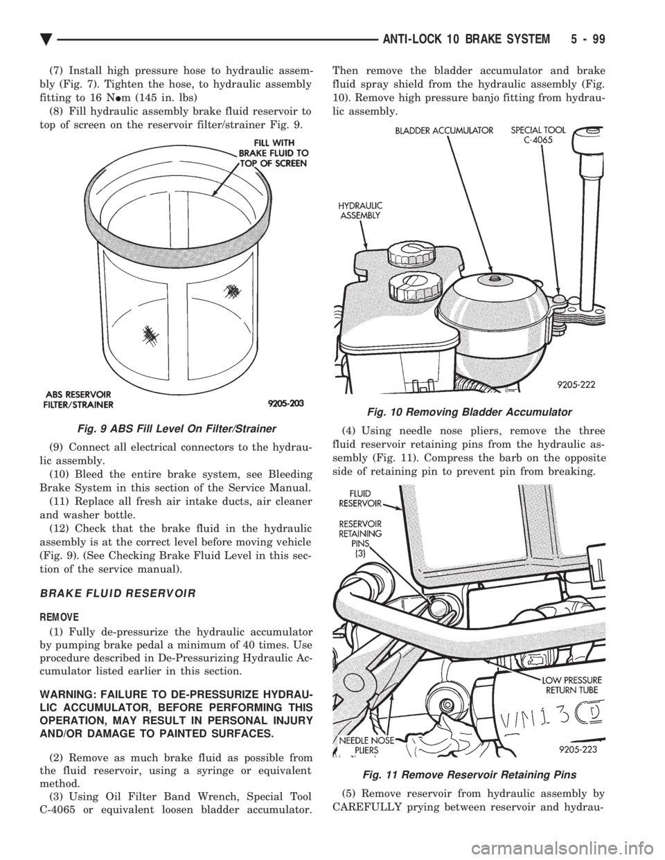
(8) Fill hydraulic assembly brake fluid reservoir to
top of screen on the reservoir filter/strainer Fig. 9.
(9) Connect all electrical connectors to the hydrau-
lic assembly. (10) Bleed the entire brake system, see Bleeding
Brake System in this section of the Service Manual. (11) Replace all fresh air intake ducts, air cleaner
and washer bottle. (12) Check that the brake fluid in the hydraulic
assembly is at the correct level before moving vehicle
(Fig. 9). (See Checking Brake Fluid Level in this sec-
tion of the service manual).
BRAKE FLUID RESERVOIR
REMOVE
(1) Fully de-pressurize the hydraulic accumulator
by pumping brake pedal a minimum of 40 times. Use
procedure described in De-Pressurizing Hydraulic Ac-
cumulator listed earlier in this section.
WARNING: FAILURE TO DE-PRESSURIZE HYDRAU-
LIC ACCUMULATOR, BEFORE PERFORMING THIS
OPERATION, MAY RESULT IN PERSONAL INJURY
AND/OR DAMAGE TO PAINTED SURFACES.
(2) Remove as much brake fluid as possible from
the fluid reservoir, using a syringe or equivalent
method. (3) Using Oil Filter Band Wrench, Special Tool
C-4065 or equivalent loosen bladder accumulator. Then remove the bladder accumulator and brake
fluid spray shield from the hydraulic assembly (Fig.
10). Remove high pressure banjo fitting from hydrau-
lic assembly.
(4) Using needle nose pliers, remove the three
fluid reservoir retaining pins from the hydraulic as-
sembly (Fig. 11). Compress the barb on the opposite
side of retaining pin to prevent pin from breaking.
(5) Remove reservoir from hydraulic assembly by
CAREFULLY prying between reservoir and hydrau-
Fig. 9 ABS Fill Level On Filter/Strainer
Fig. 10 Removing Bladder Accumulator
Fig. 11 Remove Reservoir Retaining Pins
Ä ANTI-LOCK 10 BRAKE SYSTEM 5 - 99
Page 276 of 2438
As soon as the condition goes away, the Anti-Lock
Warning Light is turned off. Although a fault code
will be set in most cases.
BENDIX ABS SYSTEMS DIAGNOSTICS
Bendix Anti-Lock 6 Brake System Diagnostics, be-
yond basic mechanical diagnostics, covered earlier in
this section. Are accomplished by using the DRB II
scan tool. See testing procedures outlined in the Ben-
dix Anti-Lock 6 Diagnostics Manual for the 1992
M.Y. vehicles. Please refer to the above mentioned manual for
any further electronic diagnostics and service proce-
dures that are required on the Bendix Anti-Lock 6
Brake System.
ON-CAR ABS BRAKE SYSTEM SERVICE
GENERAL SERVICE PRECAUTIONS
The following are general cautions which should be
observed when servicing the Anti-Lock brake system
and/or other vehicle systems. Failure to observe
these precautions may result in Anti-Lock Brake
System component damage. If welding work is to be performed on the vehicle,
using an electric arc welder, the (CAB) connector
should be disconnected during the welding operation. The (CAB) connector should never be connected or
disconnected with the ignition switch in the ON po-
sition. Many components of the Anti-Lock Brake System
are not serviceable and must be replaced as an as-
sembly. Do not disassemble any component which is
not designed to be serviced.
CHECKING BRAKE FLUID LEVEL
CAUTION: Only use brake fluid conforming to DOT
3 specifications, such as Mopar or Equivalent. Do
not use any fluid which contains a petroleum base.
Do not use a container which has been used for pe-
troleum based fluids or a container which is wet
with water. Petroleum based fluids will cause swell-
ing and distortion of rubber parts in the hydraulic
brake system. Water will mix with brake fluid, low-
ering the fluid boiling point. Keep all brake fluid
containers capped to prevent contamination. Re-
move the front cap of the master cylinder reservoir
and fill to the bottom of the split ring.
For the specific procedure for the inspection of
brake fluid level and adding of brake to the reser-
voir. Refer to the Service Adjustments Section in this
group of the service manual.
BLEEDING BENDIX ANTI-LOCK 6 BRAKE SYSTEM
The Anti-Lock Brake System must be bled anytime
air is permitted to enter the hydraulic system, due to
disconnection of brake lines, hoses of components. If the Modulator Assembly is removed from the ve-
hicle, both the Base Brake System and the Anti-Lock
Brake System must be bled using the appropriate
procedures. It is important to note that excessive air
in the brake system will cause a soft or spongy feel-
ing brake pedal. During bleeding operations, be sure that the brake
fluid level remains close to the FULL level in the
reservoir. Check the fluid level periodically during
the bleeding procedure and add DOT 3 brake fluid as
required. The Bendix Anti-Lock 6 Brake System must be
bled as two independent braking systems. The non
ABS portion of the brake system is to be bled the
same as any non ABS system. Refer to the Service
Adjustments section in this manual for the proper
bleeding procedure to be used. This brake system can
be either pressure bled or manually bled. The Anti-Lock portion of brake system MUST be
bled separately. This bleeding procedure requires the
use of the DRB II Diagnostic tester and the bleeding
sequence procedure outlined below.
ABS BLEEDING PROCEDURE (FIG. 1)
(1) Assemble and install all brake system compo-
nents on vehicle making sure all hydraulic fluid
lines are installed and properly torqued. (2) Bleed the base brake system. Using the stan-
dard pressure or manual bleeding procedure as out-
lined in the Service Adjustments section of this
service manual. To perform the bleeding procedure on the ABS
unit. The battery and acid shield must be removed
from the vehicle. Reconnect the vehicles battery, to
the vehicles positive and negative battery cables us-
ing jumper cables. This is necessary to allow access
to the 4 bleeder screws located on the top of the Mod-
ulator assembly. (3) Connect the DRB II Diagnostics Tester to the
diagnostics connector. Located behind the Fuse Panel
access cover on the lower section of the dash panel to
the left of the steering column. (It is a blue 6 way
connector). (4) Using the DRB II check to make sure the
(CAB) does not have any fault codes stored. If it does
remove them using the DRB II.
5 - 126 ANTI-LOCK 6 BRAKE SYSTEM Ä
Page 290 of 2438
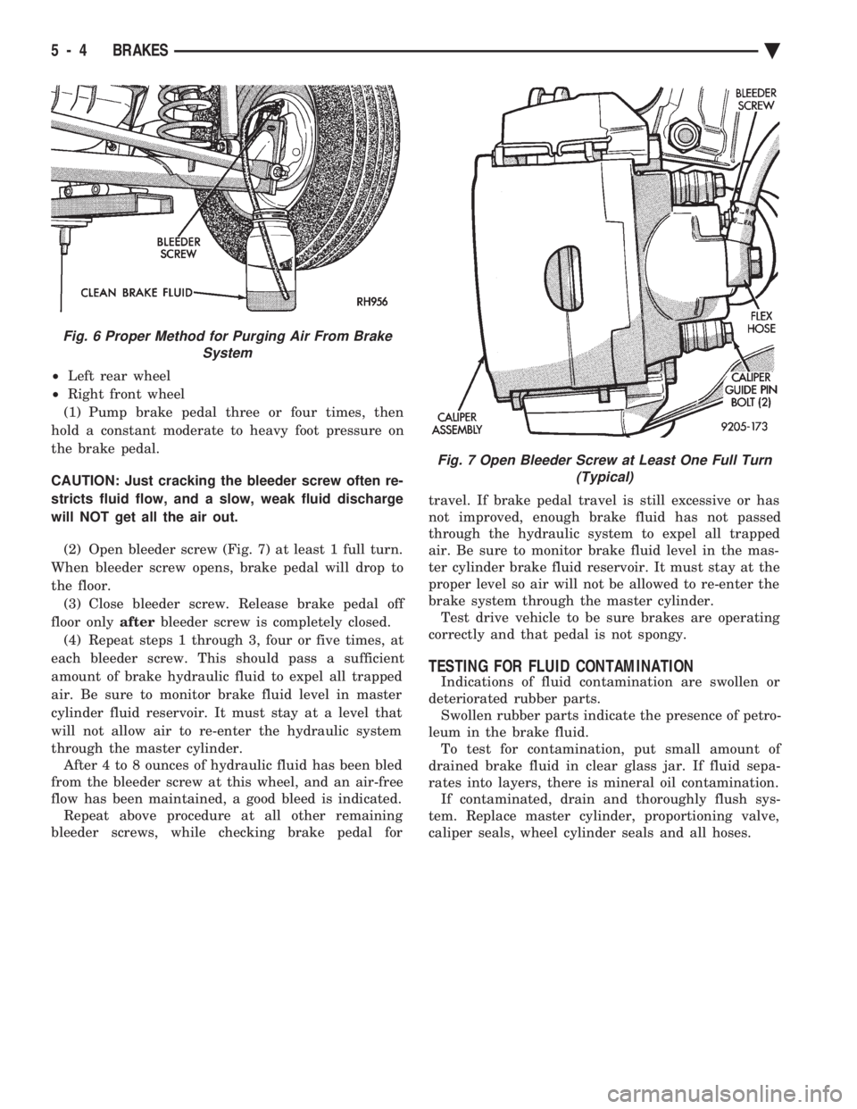
² Left rear wheel
² Right front wheel
(1) Pump brake pedal three or four times, then
hold a constant moderate to heavy foot pressure on
the brake pedal.
CAUTION: Just cracking the bleeder screw often re-
stricts fluid flow, and a slow, weak fluid discharge
will NOT get all the air out.
(2) Open bleeder screw (Fig. 7) at least 1 full turn.
When bleeder screw opens, brake pedal will drop to
the floor. (3) Close bleeder screw. Release brake pedal off
floor only afterbleeder screw is completely closed.
(4) Repeat steps 1 through 3, four or five times, at
each bleeder screw. This should pass a sufficient
amount of brake hydraulic fluid to expel all trapped
air. Be sure to monitor brake fluid level in master
cylinder fluid reservoir. It must stay at a level that
will not allow air to re-enter the hydraulic system
through the master cylinder. After 4 to 8 ounces of hydraulic fluid has been bled
from the bleeder screw at this wheel, and an air-free
flow has been maintained, a good bleed is indicated. Repeat above procedure at all other remaining
bleeder screws, while checking brake pedal for travel. If brake pedal travel is still excessive or has
not improved, enough brake fluid has not passed
through the hydraulic system to expel all trapped
air. Be sure to monitor brake fluid level in the mas-
ter cylinder brake fluid reservoir. It must stay at the
proper level so air will not be allowed to re-enter the
brake system through the master cylinder. Test drive vehicle to be sure brakes are operating
correctly and that pedal is not spongy.
TESTING FOR FLUID CONTAMINATION
Indications of fluid contamination are swollen or
deteriorated rubber parts. Swollen rubber parts indicate the presence of petro-
leum in the brake fluid. To test for contamination, put small amount of
drained brake fluid in clear glass jar. If fluid sepa-
rates into layers, there is mineral oil contamination. If contaminated, drain and thoroughly flush sys-
tem. Replace master cylinder, proportioning valve,
caliper seals, wheel cylinder seals and all hoses.
Fig. 6 Proper Method for Purging Air From Brake System
Fig. 7 Open Bleeder Screw at Least One Full Turn(Typical)
5 - 4 BRAKES Ä
Page 311 of 2438
LATCHING VERSUS NON-LATCHING ABS FAULTS
Some faults detected by the CAB are latching; the
fault is latched and ABS is disabled until the igni-
tion switch is reset. Thus ABS is disabled even if the
original fault has disappeared. Other faults are non-
latching; any warning lights that are turned on, are
only turned on as long as the fault condition exists.
As soon as the condition goes away, the Antilock
Warning Light is turned off. Although a fault code
will be set in most cases.
BENDIX ANTILOCK 4 BRAKE SYSTEM DIAGNOSTICS
Bendix Antilock 4 Brake System Diagnostics, be-
yond basic mechanical diagnostics, covered earlier in
this section, are accomplished by using the DRB scan
tool. See testing procedures outlined in the 1994 Ben-
dix Antilock 4 Diagnostics Manual. Please refer to the above mentioned manual for
any further electronic diagnostics and service proce-
dures that are required on the Bendix Antilock 4
Brake System.
ON-CAR ABS BRAKE SYSTEM SERVICE
GENERAL SERVICE PRECAUTIONS
The following are general cautions which should be
observed when servicing the Bendix Antilock 4
Brake System and other vehicle electronic systems.
Failure to observe these precautions may result in
Antilock Brake System component damage. If welding work is to be performed on a vehicle us-
ing an electric arc welder, disconnect the 60 way wir-
ing harness connector from the CAB, prior to
performing the welding operation. The wiring harness connector should never be con-
nected or disconnected from the CAB with the igni-
tion key in the ON or Run position. (3) Most components making up the assemblies of
the Bendix Antilock 4 Brake System can not be ser-
viced separately from those assemblies. This will re-
quire replacement of the complete assembly for the
servicing of these components. Do not disassemble
any component from an assembly which is desig-
nated as non-serviceable.
CHECKING BRAKE FLUID LEVEL
CAUTION: Only use brake fluid conforming to DOT
3 specifications, such as Mopar or Equivalent. Do
not use any fluid which contains a petroleum base.
Do not use a container which has been used for pe-
troleum based fluids or a container which is wet
with water. Petroleum based fluids will cause swell-
ing and distortion of rubber parts in the hydraulic
brake system. Water will mix with brake fluid, low-
ering the boiling point of the brake fluid, possibly causing brake fluid to boil resulting in brake fade.
Keep all brake fluid containers capped to prevent
contamination. Remove the front cap of the master
cylinder reservoir and fill to the bottom of the split
ring.
For the specific procedure for the inspection of
brake fluid level and adding of brake to the reser-
voir. Refer to the Service Adjustments Section in this
group of the service manual.
BLEEDING BENDIX ANTILOCK 4 BRAKE SYSTEM
The base brakes and Antilock Brake System must
be bled anytime air is permitted to enter the hydrau-
lic system, due to disconnection of brake lines, hoses
or components. If the Antilock Modulator Assembly is removed
from the vehicle, both the Base Brake System and
the Antilock Brake System must be bled using the
appropriate procedure. It is important to note that
excessive air in the brake system will cause a soft or
spongy feeling brake pedal. During brake bleeding operations, ensure that
brake fluid level remains close to the FULL level in
the reservoir. Check brake fluid level periodically
during bleeding procedure, adding DOT 3 brake fluid
as required.
CAUTION: The base brake and Antilock brake hy-
draulic systems, on the Bendix Antilock 4 Brake
System, can NOT be bled using any type of brake
pressure bleeding equipment. This type of bleeding
equipment does not develop the pressure required
in the brake hydraulic system, to adequately bleed
all trapped air. The only approved method for bleed-
ing air out of the hydraulic system on vehicles
equipped with the Bendix Antilock 4 Brake System,
is the manual procedure of pressurizing the hydrau-
lic system using constant, moderate to heavy foot
pressure on the brake pedal.
The Bendix Antilock 4 Brake System must be bled
as two independent brake systems. The non ABS por-
tion of the brake system is to be bled the same as
any non ABS system. Refer to the Service Adjust-
ments section in this manual for the proper bleeding
procedure to be used. The Bendix Antilock 4 Brake
System can only be bled using a manual method of
pressurizing the brakes hydraulic system. The Antilock portion of brake system MUST be
bled separately. This bleeding procedure requires the
use of the DRB Diagnostic tester and the bleeding se-
quence procedure outlined below.
Ä ANTILOCK 4 BRAKE SYSTEM 5 - 25