1993 CHEVROLET DYNASTY checking oil
[x] Cancel search: checking oilPage 359 of 2438
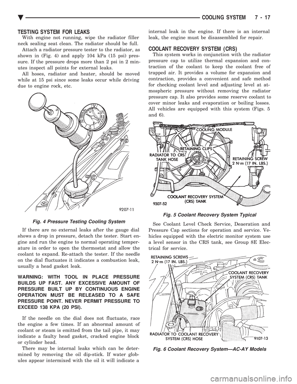
TESTING SYSTEM FOR LEAKS
With engine not running, wipe the radiator filler
neck sealing seat clean. The radiator should be full. Attach a radiator pressure tester to the radiator, as
shown in (Fig. 4) and apply 104 kPa (15 psi) pres-
sure. If the pressure drops more than 2 psi in 2 min-
utes inspect all points for external leaks. All hoses, radiator and heater, should be moved
while at 15 psi since some leaks occur while driving
due to engine rock, etc.
If there are no external leaks after the gauge dial
shows a drop in pressure, detach the tester. Start en-
gine and run the engine to normal operating temper-
ature in order to open the thermostat and allow the
coolant to expand. Re-attach the tester. If the needle
on the dial fluctuates it indicates a combustion leak,
usually a head gasket leak.
WARNING: WITH TOOL IN PLACE PRESSURE
BUILDS UP FAST. ANY EXCESSIVE AMOUNT OF
PRESSURE BUILT UP BY CONTINUOUS ENGINE
OPERATION MUST BE RELEASED TO A SAFE
PRESSURE POINT. NEVER PERMIT PRESSURE TO
EXCEED 138 KPA (20 PSI).
If the needle on the dial does not fluctuate, race
the engine a few times. If an abnormal amount of
coolant or steam is emitted from the tail pipe, it may
indicate a faulty head gasket, cracked engine block
or cylinder head. There may be internal leaks which can be deter-
mined by removing the oil dip-stick. If water glob-
ules appear intermixed with the oil it will indicate a internal leak in the engine. If there is an internal
leak, the engine must be disassembled for repair.
COOLANT RECOVERY SYSTEM (CRS)
This system works in conjunction with the radiator
pressure cap to utilize thermal expansion and con-
traction of the coolant to keep the coolant free of
trapped air. It provides a volume for expansion and
contraction, provides a convenient and safe method
for checking coolant level and adjusting level at at-
mospheric pressure without removing the radiator
pressure cap. It also provides some reserve coolant to
cover minor leaks and evaporation or boiling losses.
All vehicles are equipped with this system (Figs. 5
and 6).
See Coolant Level Check Service, Deaeration and
Pressure Cap sections for operation and service. Ve-
hicles equipped with the electric monitor system use
a level sensor in the CRS tank, see Group 8E Elec-
trical for service.
Fig. 4 Pressure Testing Cooling System
Fig. 5 Coolant Recovery System Typical
Fig. 6 Coolant Recovery SystemÐAC-AY Models
Ä COOLING SYSTEM 7 - 17
Page 360 of 2438
RADIATOR PRESSURE CAP
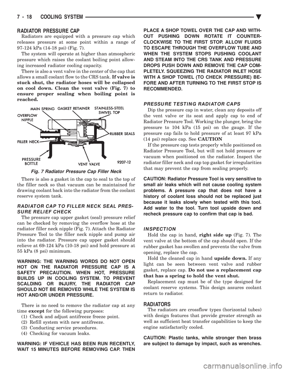
Radiators are equipped with a pressure cap which
releases pressure at some point within a range of
97-124 kPa (14-18 psi) (Fig. 7). The system will operate at higher than atmospheric
pressure which raises the coolant boiling point allow-
ing increased radiator cooling capacity. There is also a vent valve in the center of the cap that
allows a small coolant flow to the CRS tank. If valve is
stuck shut, the radiator hoses will be collapsed
on cool down. Clean the vent valve (Fig. 7) to
ensure proper sealing when boiling point is
reached.
There is also a gasket in the cap to seal to the top of
the filler neck so that vacuum can be maintained for
drawing coolant back into the radiator from the coolant
reserve system tank.
RADIATOR CAP TO FILLER NECK SEAL PRES- SURE RELIEF CHECK
The pressure cap upper gasket (seal) pressure relief
can be checked by removing the overflow hose at the
radiator filler neck nipple (Fig. 7). Attach the Radiator
Pressure Tool to the filler neck nipple and pump air
into the radiator. Pressure cap upper gasket should
relieve at 69-124 kPa (10-18 psi) and hold pressure at
55 kPa (8 psi) minimum.
WARNING: THE WARNING WORDS DO NOT OPEN
HOT ON THE RADIATOR PRESSURE CAP IS A
SAFETY PRECAUTION. WHEN HOT, PRESSURE
BUILDS UP IN COOLING SYSTEM. TO PREVENT
SCALDING OR INJURY, THE RADIATOR CAP
SHOULD NOT BE REMOVED WHILE THE SYSTEM IS
HOT AND/OR UNDER PRESSURE.
There is no need to remove the radiator cap at any
time except for the following purposes:
(1) Check and adjust antifreeze freeze point.
(2) Refill system with new antifreeze.
(3) Conducting service procedures.
(4) Checking for vacuum leaks.
WARNING: IF VEHICLE HAS BEEN RUN RECENTLY,
WAIT 15 MINUTES BEFORE REMOVING CAP. THEN PLACE A SHOP TOWEL OVER THE CAP AND WITH-
OUT PUSHING DOWN ROTATE IT COUNTER-
CLOCKWISE TO THE FIRST STOP. ALLOW FLUIDS
TO ESCAPE THROUGH THE OVERFLOW TUBE AND
WHEN THE SYSTEM STOPS PUSHING COOLANT
AND STEAM INTO THE CRS TANK AND PRESSURE
DROPS PUSH DOWN AND REMOVE THE CAP COM-
PLETELY. SQUEEZING THE RADIATOR INLET HOSE
WITH A SHOP TOWEL (TO CHECK PRESSURE) BE-
FORE AND AFTER TURNING TO THE FIRST STOP IS
RECOMMENDED.
PRESSURE TESTING RADIATOR CAPS
Dip the pressure cap in water, clean any deposits off
the vent valve or its seat and apply cap to end of
Radiator Pressure Tool. Working the plunger, bring the
pressure to 104 kPa (15 psi) on the gauge. If the
pressure cap fails to hold pressure of at least 97 kPa
(14 psi) replace cap. See CAUTION
If the pressure cap tests properly while positioned on
Radiator Pressure Tool, but will not hold pressure or
vacuum when positioned on the radiator. Inspect the
radiator filler neck and cap top gasket for irregularities
that may prevent the cap from sealing properly.
CAUTION: Radiator Pressure Tool is very sensitive to
small air leaks which will not cause cooling system
problems. A pressure cap that does not have a
history of coolant loss should not be replaced just
because it leaks slowly when tested with this tool.
Add water to the tool. Turn tool upside down and
recheck pressure cap to confirm that cap is bad.
INSPECTION
Hold the cap in hand, right side up(Fig. 7). The
vent valve at the bottom of the cap should open. If the
rubber gasket has swollen and prevents the valve from
opening, replace the cap. Hold the cleaned cap in hand upside down.If any
light can be seen between vent valve and rubber
gasket, replace cap. Do not use a replacement cap
that has a spring to hold the vent shut. Replacement cap must be of the type designed for
coolant reserve systems. This design assures coolant
return to radiator.
RADIATORS
The radiators are crossflow types (horizontal tubes)
with design features that provide greater strength as
well as sufficient heat transfer capabilities to keep the
engine satisfactorily cooled.
CAUTION: Plastic tanks, while stronger then brass
are subject to damage by impact, such as wrenches.
Fig. 7 Radiator Pressure Cap Filler Neck
7 - 18 COOLING SYSTEM Ä
Page 388 of 2438
relay to starter solenoid for loose or corroded connec-
tions. Particularly at starter terminals.
² Repeat test. If engine still fails to crank properly,
trouble is within starter or starter mounted solenoid,
and it must be removed for repairs. Refer to Group
8B, Battery/Starter/Generator Service, Starter re-
placement.
STARTER RELAY TEST
WARNING: CHECK TO ENSURE THAT THE TRANS-
MISSION IS IN PARK OR NEUTRAL WITH THE
PARKING BRAKE APPLIED
(1) Verify battery condition. Battery must be in
good condition with a full charge before performing
any starter tests. Refer to Battery Tests. (2) Perform the preceding starter solenoid tests
BEFORE performing starter relay tests. Refer to
Starter Solenoid Test. (3) Locate and remove the starter relay. For
starter relay locations, refer to Starter Solenoid Test
(Fig. 13 or 14). (4) After the starter relay has been located and re-
moved, refer to Starter Relay Tests (Fig. 15).
NEUTRAL STARTING AND BACK-UP SWITCH
AUTOMATIC TRANSMISSION ONLY
For electrical diagnostics, when checking starter
circuits, refer to Starter Relay Tests (Fig. 15). For replacement of switch, refer to Group 21, Tran-
saxle, Neutral Starting and Switch Replacement.
STARTER INTERLOCK SWITCHÐCLUTCH PEDAL MOUNTED
MANUAL TRANSMISSION ONLY
For electrical diagnostics, refer to the Starter Relay
Tests. For replacement and/or adjustment of the switch,
refer to Group 6, Manual Transaxle Clutch, Manual
Transaxle Starter Interlock Switch.
IGNITION SWITCH TEST
After testing the starter solenoid and relay, test ig-
nition switch and wiring. Refer to Group 8D, Ignition
Systems, or the Front Wheel Drive Car Wiring Dia-
grams Service Manual. Check all wiring for opens or
shorts, and all connectors for being loose or corroded.
BENCH TESTING STARTER SOLENOID
(1) Disconnect field coil wire from field coil termi-
nal (Fig. 16 or 17). (2) Check for continuity between solenoid terminal
and field coil terminal with a continuity tester. Con-
tinuity should be detected (Fig. 18 or 19). (3) Check for continuity between solenoid terminal
and solenoid housing (Fig. 20 or 21). Continuity
should be detected. If continuity is detected, solenoid
is good. (4) If continuity is not detected in either test, sole-
noid has an open circuit and is defective. If equipped
with:
² BOSCH STARTER: Replace the solenoid.
² NIPPONDENSO STARTER: Replace the starter
assembly.
8A - 16 BATTERY/STARTING/CHARGING SYSTEMS DIAGNOSTICS Ä
Page 454 of 2438

make sure that the spark plugs are firing. Inspect the
distributor rotor, cap, spark plug cables, and spark
plugs. If they are in proper working order, the ignition
system is not the reason why the engine will not start.
Inspect the fuel system and engine for proper opera-
tion.
FAILURE TO START TESTÐ2.5L TBI AND 3.0L
ENGINES
Before proceeding with this test make sure
Testing For Spark At Coil has been performed.
Failure to do this may lead to unnecessary diag-
nostic time and wrong test results.
WARNING: BE SURE TO APPLY PARKING BRAKE
AND/OR BLOCK WHEELS BEFORE PERFORMING
ANY TEST WITH THE ENGINE RUNNING.
(1) Battery voltage must be at least 12.4 volts to
perform test. (2) Crank the engine for 5 seconds while monitoring
the voltage at the coil positive (+) terminal (Fig. 2 or
Fig. 3). If the voltage remains near zero during the
entire period of cranking, refer to Group 14 for On-
Board Diagnostic checks. Also, refer to the DRBII scan
tool and the appropriate Powertrain Diagnostic Proce-
dures manual. These checks will help diagnose prob-
lems with the PCM and auto shutdown relay. (3) If voltage is at near-battery voltage and drops to
zero after 1-2 seconds of cranking, refer to On-Board
Diagnostic in Group 14. Also, refer to the DRBII scan
tool and the appropriate Powertrain Diagnostic Proce-
dures manual. These tests will help check the distribu-
tor reference pickup circuit to the PCM. (4) If voltage remains at near battery voltage during
the entire 5 seconds, with the key off,remove the
PCM 60-way connector. Check the 60-way connector
for any terminals that are pushed out or loose. (5) Remove the connector to coil (+) and connect a
jumper wire between battery (+) and coil (+). (6) Using the special jumper (Fig. 4), momentarily ground terminal #19 of the 60-way connector (Fig.
5). A spark should be generated when the ground is
removed.
(7) If spark is generated, replace the PCM.
(8) If no spark is seen, use the special jumper to
ground the coil (-) terminal directly. (9) If spark is produced, inspect wiring harness for
an open condition.
Fig. 2 Coil TerminalsÐ2.2L TBI, 2.5L TBI and 2.5L MPI Engines
Fig. 3 Coil TerminalsÐ3.0L Engine
Fig. 4 Special Jumper to Ground Coil Negative
Fig. 1 Checking for Spark
8D - 12 IGNITION SYSTEMS Ä
Page 478 of 2438

(Fig. 4). Secondary resistance should be 11,600 to
15,800 ohms. Replace the coil if resistance is not
within tolerance.
FAILURE TO START TESTÐTURBO III ENGINE
(1) Determine that sufficient battery voltage (12.4
volts nominal) is present for the cranking and igni-
tion systems. (2) Connect a voltmeter to the wiring harness coil
connector at the B+ pin (Fig. 5).
(3) Crank the engine for 5 seconds while monitor-
ing the voltage at the B+ connector terminal. If the
voltage remains near zero during the entire period of
cranking, check the auto shutdown relay and PCM.
Refer to DRBII scan tool and the appropriate Power-
train Diagnostic Procedures manual. Refer to Group
14 for description of On Board Diagnostics. (4) If voltage is at near-battery voltage, and drops
to zero after 1-2 seconds of cranking, check the cam-
shaft position sensor and crankshaft position sensor
and their circuits. Refer to the DRBII scan tool and
the appropriate Powertrain Diagnostic Procedure
manual. Refer to Group 14 for a description of On-
Board Diagnostics. (5) If voltage remains at near-battery voltage dur-
ing the entire 5 seconds, turn the key off, remove the PCM 60-way connector. Check the 60-way for any
terminals loose from the connector (push-out).
TESTING FOR SPARK AT COILÐ3.3L AND 3.8L
ENGINES
WARNING: THE ENGINE DIRECT IGNITION SYSTEM
GENERATES APPROXIMATELY 40,000 VOLTS. PER-
SONAL INJURY COULD RESULT FROM CONTACT
WITH THIS SYSTEM.
The coil pack contains 3 independent coils. Each coil
must be checked individually.
CAUTION: Spark plug wire damage may occur if the
spark plug is moved more than 1/4 inch away from the
engine ground.
Remove the cable from number 2 spark plug. Insert a
clean spark plug into the spark plug boot, and ground
plug to the engine (Fig. 1). Crank the engine and look for spark across the
electrodes of the spark plug. Repeat the above test for
the five remaining cylinders. If there is no spark
during all cylinder tests, proceed to the failure to start
test. If one or more tests indicate irregular, weak, or no
spark, proceed to Check Coil Test.
WARNING: THE DIRECT IGNITION SYSTEM GENER-
ATES APPROXIMATELY 40,000 VOLTS. PERSONAL
INJURY COULD RESULT FROM CONTACT WITH THIS
SYSTEM.
CHECK COIL TESTÐ3.3L AND 3.8L ENGINES
Coil one fires cylinders 1 and 4, coil two fires
cylinders 2 and 5, coil three fires cylinders three
and six. Each coil tower is labeled with the number of the
corresponding cylinder. (1) Remove the ignition cables and measure the
resistance of the cables. Resistance must be between
3,000 to 12,000 ohms per foot of cable. Replace any
cable not within tolerance. (2) Disconnect the electrical connector from the coil
pack (Fig. 6). (3) Measure the primary resistance of each coil. At
the coil, connect an ohmmeter between the B+ pin and
the pin corresponding to the cylinders in question (Fig.
7). Resistance on the primary side of each coil should be
0.5 - 0.7 ohm. Replace the coil if resistance is not within
tolerance. (4) Remove ignition cables from the secondary tow-
ers of the coil. Measure the secondary resistance of the
coil between the towers of each individual coil (Fig. 8).
Refer to the Coil Specifications Chart in the Specifica-
tions section of this group. Replace the coil if resistance
is not within tolerance.
Fig. 4 Checking Ignition Coil Secondary ResistanceÐTurbo III Engines
Fig. 5 Wiring Harness Coil ConnectorÐTurbo III Engine
8D - 36 IGNITION SYSTEMS Ä
Page 479 of 2438

FAILURE TO START TEST
This no-start test checks the camshaft position sen-
sor and crankshaft position sensor. The powertrain control module (PCM) supplies 8.0
volts to the camshaft position sensor and crankshaft
position sensor through one circuit. If the 8.0-volt
supply circuit shorts to ground, neither sensor will
produce a signal (output voltage to the PCM). When the ignition key is turned and left in the On
position , the PCM automatically energizes the auto shutdown (ASD) relay. However, the PCM de-energizes
the relay within one second because it has not received
a crankshaft position sensor signal indicating engine
rotation.
During cranking, the ASD relay will not energize
until the PCM receives a crankshaft signal. Secondly,
the ASD relay remains energized only if the PCM
senses a camshaft position sensor signal immediately
after detecting the crankshaft position sensor signal. (1) Check battery voltage. Voltage should approxi-
mately 12.66 volts or higher to perform failure to start
test. (2) Disconnect the harness connector from the coil
pack (Fig. 2). (3) Connect a test light to the B+ (battery voltage)
terminal of the coil electrical connector and ground.
The wire for the B+ terminal is dark green with a black
tracer. (4) Turn the ignition key to the ON position.The
test light should flash On and then Off. Do not turn
the Key to off position, leave it in the On position .
(a) If the test light flashes momentarily, the PCM
grounded the auto shutdown (ASD) relay. Proceed to
step 5. (b) If the test light did not flash, the ASD relay did
not energize. The cause is either the relay or one of
the relay circuits. Use the DRBII scan tool to test the
ASD relay and circuits. Refer to the appropriate
Powertrain Diagnostics Procedure Manual. Refer to
the wiring diagrams section for circuit information.
(5) Crank the engine. If the key was placed in the off
position after step 4, place the key in the On position
before cranking. Wait for the test light to flash once,
then crank the engine. (a) If the test light momentarily flashes during
cranking, the PCM is not receiving a camshaft posi-
tion sensor signal. Use the DRBII scan tool to test the
camshaft position sensor and sensor circuits. Refer to
the appropriate Powertrain Diagnostics Procedure
Manual. Refer to the wiring diagrams section for
circuit information. (b) If the test light did not flash during cranking,
unplug the camshaft position sensor connector. Turn
the ignition key to the off position. Turn the key to
the On position, wait for the test light to momen-
tarily flash once, then crank the engine. If the test
light momentarily flashes, the camshaft position
sensor is shorted and must be replaced. If the light
did not flash, the cause of the no-start is in either the
crankshaft position sensor/camshaft position sensor
8.0-volt supply circuit, or the crankshaft position
sensor 5-volt output or ground circuits. Use the
DRBII scan tool to test the crankshaft position sen-
sor and the sensor circuits.
Fig. 6 Ignition Coil Electrical Connection
Fig. 7 Ignition Coil Terminal Identification
Fig. 8 Checking Ignition Coil Secondary Resistance
Ä IGNITION SYSTEMS 8D - 37
Page 494 of 2438
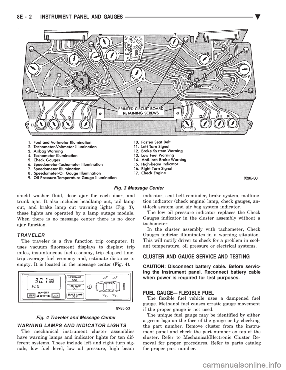
shield washer fluid, door ajar for each door, and
trunk ajar. It also includes headlamp out, tail lamp
out, and brake lamp out warning lights (Fig. 3),
these lights are operated by a lamp outage module.
When there is no message center there is no door
ajar function.
TRAVELER
The traveler is a five function trip computer. It
uses vacuum fluorescent displays to display: trip
miles, instantaneous fuel economy, trip elapsed time,
trip average fuel economy and, estimate distance to
empty. It is located in the message center (Fig. 4).
WARNING LAMPS AND INDICATOR LIGHTS
The mechanical instrument cluster assemblies
have warning lamps and indicator lights for ten dif-
ferent systems. These include left and right turn sig-
nals, low fuel level, low oil pressure, high beam indicator, seat belt reminder, brake system, malfunc-
tion indicator (check engine) lamp, check gauges, an-
ti-lock system and air bag system indicator. The low oil pressure indicator replaces the Check
Gauges indicator in the cluster assembly without a
tachometer. In the cluster assembly with tachometer, Check
Gauges indictor illuminates in a warning situation.
This will notify driver to check for a problem in cool-
ant temperature, oil pressure or electrical systems.
CLUSTER AND GAUGE SERVICE AND TESTING
CAUTION: Disconnect battery cable. Before servic-
ing the instrument panel. Reconnect battery cable
when power is required for test purposes.
FUEL GAUGEÐFLEXIBLE FUEL
The flexible fuel vehicle uses a dampened fuel
gauge. Methanol fuel causes erratic gauge movement
if the proper gauge is not used. The unique fuel gauge may be identified by either
a green logo on the face of the gauge or by checking
the part number. Remove cluster from the instru-
ment panel and check the part number on top of the
cluster. Refer to Mechanical/Electronic Cluster Re-
moval for proper procedures. Refer to parts catalog
for proper part number.
Fig. 3 Message Center
Fig. 4 Traveler and Message Center
8E - 2 INSTRUMENT PANEL AND GAUGES Ä
Page 501 of 2438
(3) When testing temperature, allow the engine to
run until the vehicle reaches a normal operating
temperature. Turn ignition OFF, and remove gauge
from cluster. (a) Testing oil pressure gauge, engine needs to
be running. (b) Measure and record the resistance between
sending unit pin and ground pin of the gauge in
question. Refer to Gauge Calibration. (c) It is important to have the same engine tem-
perature and engine speed when checking temper-
ature and oil pressure gauges position. The time
between gauge position reading and sending unit
measuring should be kept to a minimum. (d) If resistance and gauge position are not sim-
ilar, replace gauge. (e) If OK, test resistance from the sending unit
to the cluster connector. (f) If resistance reading is different, check
printed circuit board for contact to cluster connec-
tor. (g) If OK and contacts are not distorted, replace
printed circuit board. (h) If everything checks out OK, refer to sending
unit test.
(4) If fuel gauge does not meet specifications, refer
to Group 14, Fuel for the test procedure.
GAUGE CALIBRATION
(1) Remove the gauge.
(2) Check for ignition voltage and ground to the
gauge. (3) With the ignition key in the OFF position, re-
place gauge. Turn the ignition key to the ON posi-
tion. To test oil pressure gauge engine must be
running. When testing oil or temperature gauge the
engine should be at normal operating temperature.
Record the gauge position. (4) Remove gauge and record the resistance be-
tween the sending unit pin and the gauge ground
pin. When checking gauges, it is important to have
the same engine temperature and speed when noting
gauge position. The time between gauge reading and
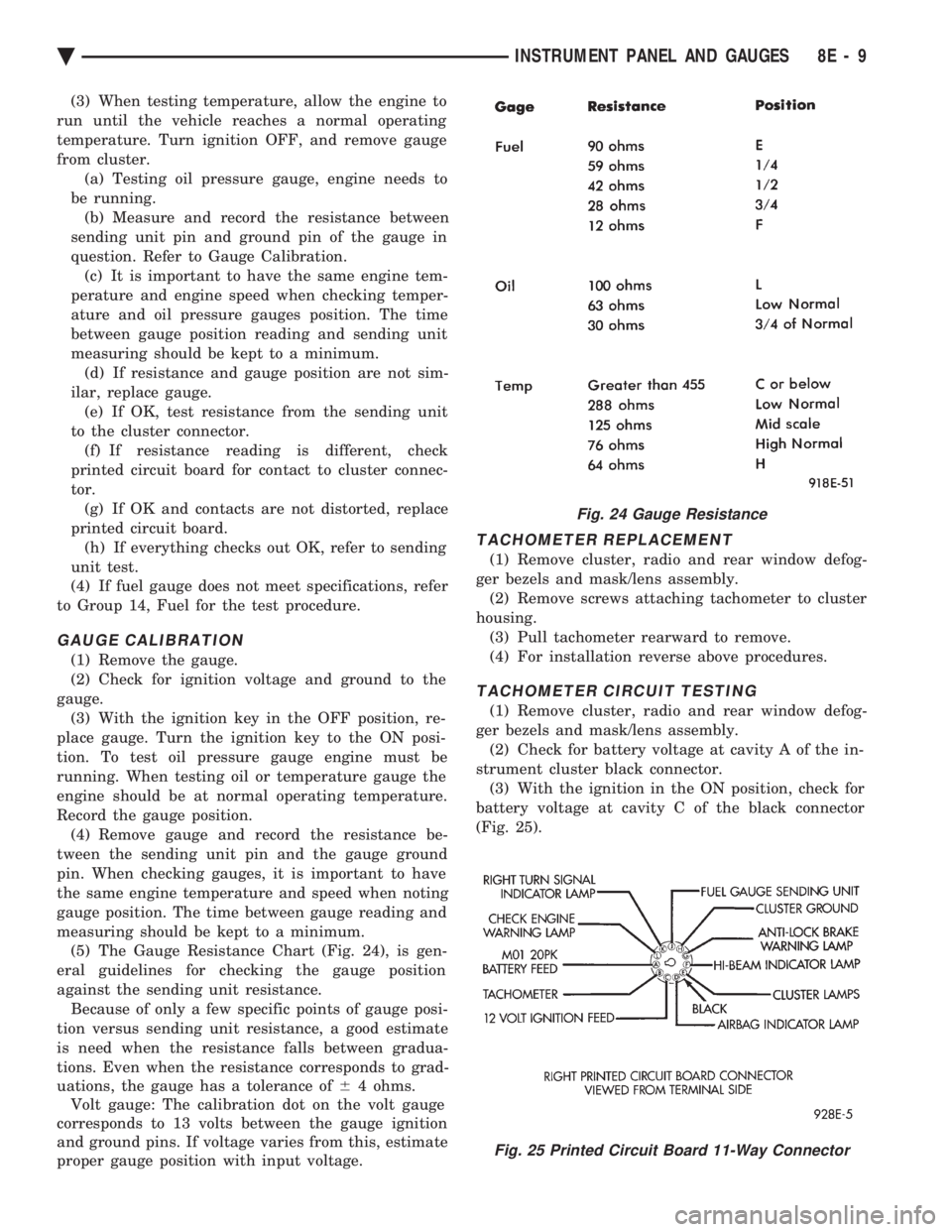
measuring should be kept to a minimum. (5) The Gauge Resistance Chart (Fig. 24), is gen-
eral guidelines for checking the gauge position
against the sending unit resistance. Because of only a few specific points of gauge posi-
tion versus sending unit resistance, a good estimate
is need when the resistance falls between gradua-
tions. Even when the resistance corresponds to grad-
uations, the gauge has a tolerance of 64 ohms.
Volt gauge: The calibration dot on the volt gauge
corresponds to 13 volts between the gauge ignition
and ground pins. If voltage varies from this, estimate
proper gauge position with input voltage.
TACHOMETER REPLACEMENT
(1) Remove cluster, radio and rear window defog-
ger bezels and mask/lens assembly. (2) Remove screws attaching tachometer to cluster
housing. (3) Pull tachometer rearward to remove.
(4) For installation reverse above procedures.
TACHOMETER CIRCUIT TESTING
(1) Remove cluster, radio and rear window defog-
ger bezels and mask/lens assembly. (2) Check for battery voltage at cavity A of the in-
strument cluster black connector. (3) With the ignition in the ON position, check for
battery voltage at cavity C of the black connector
(Fig. 25).
Fig. 24 Gauge Resistance
Fig. 25 Printed Circuit Board 11-Way Connector
Ä INSTRUMENT PANEL AND GAUGES 8E - 9