1993 CHEVROLET DYNASTY checking oil
[x] Cancel search: checking oilPage 1574 of 2438
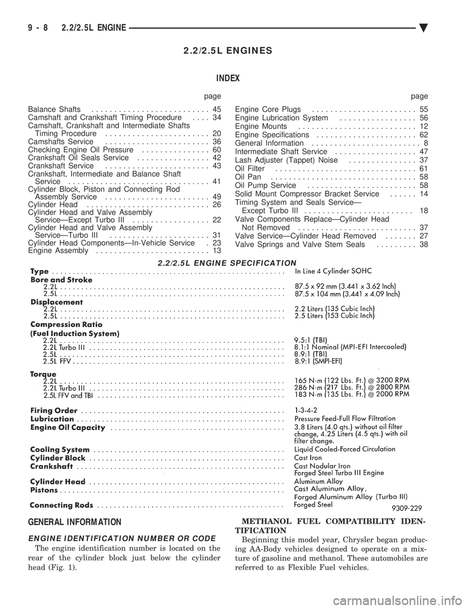
2.2/2.5L ENGINES INDEX
page page
Balance Shafts .......................... 45
Camshaft and Crankshaft Timing Procedure .... 34
Camshaft, Crankshaft and Intermediate Shafts Timing Procedure ....................... 20
Camshafts Service ....................... 36
Checking Engine Oil Pressure ............... 60
Crankshaft Oil Seals Service ................ 42
Crankshaft Service ....................... 43
Crankshaft, Intermediate and Balance Shaft Service ............................... 41
Cylinder Block, Piston and Connecting Rod Assembly Service ....................... 49
Cylinder Head ........................... 26
Cylinder Head and Valve Assembly ServiceÐExcept Turbo III ................. 22
Cylinder Head and Valve Assembly ServiceÐTurbo III ...................... 31
Cylinder Head ComponentsÐIn-Vehicle Service . 23
Engine Assembly ......................... 13 Engine Core Plugs
....................... 55
Engine Lubrication System ................. 56
Engine Mounts .......................... 12
Engine Specifications ...................... 62
General Information ........................ 8
Intermediate Shaft Service .................. 47
Lash Adjuster (Tappet) Noise ............... 37
Oil Filter ............................... 61
Oil Pan ................................ 58
Oil Pump Service ........................ 58
Solid Mount Compressor Bracket Service ...... 14
Timing System and Seals ServiceÐ Except Turbo III ........................ 18
Valve Components ReplaceÐCylinder Head Not Removed .......................... 37
Valve ServiceÐCylinder Head Removed ....... 27
Valve Springs and Valve Stem Seals ......... 38
GENERAL INFORMATION
ENGINE IDENTIFICATION NUMBER OR CODE
The engine identification number is located on the
rear of the cylinder block just below the cylinder
head (Fig. 1). METHANOL FUEL COMPATIBILITY IDEN-
TIFICATION Beginning this model year, Chrysler began produc-
ing AA-Body vehicles designed to operate on a mix-
ture of gasoline and methanol. These automobiles are
referred to as Flexible Fuel vehicles.
2.2/2.5L ENGINE SPECIFICATION
9 - 8 2.2/2.5L ENGINE Ä
Page 1593 of 2438
Cylinder Head: Top of bearing caps painted green
and O/SJ stamped rearward of oil gallery plug on end
of head. Camshaft: Barrel of camshaft painted greenand
O/SJ stamped on end of shaft.
CLEANING
Remove all gasket material from cylinder head and
block. Be careful not gouge or scratch the aluminum
head sealing surface.
INSTALLATION
CAUTION: Head bolt diameter is 11mm. These bolts
are identified with 11 on the head of the bolt. 10mm
bolts will thread into the 11mm hole but will strip the
cylinder block bolt hole .
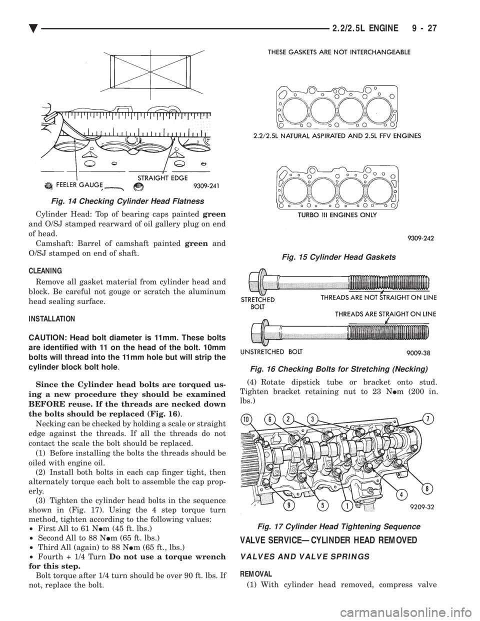
Since the Cylinder head bolts are torqued us-
ing a new procedure they should be examined
BEFORE reuse. If the threads are necked down
the bolts should be replaced (Fig. 16) .
Necking can be checked by holding a scale or straight
edge against the threads. If all the threads do not
contact the scale the bolt should be replaced. (1) Before installing the bolts the threads should be
oiled with engine oil. (2) Install both bolts in each cap finger tight, then
alternately torque each bolt to assemble the cap prop-
erly. (3) Tighten the cylinder head bolts in the sequence
shown in (Fig. 17). Using the 4 step torque turn
method, tighten according to the following values:
² First All to 61 N Im (45 ft. lbs.)
² Second All to 88 N Im (65 ft. lbs.)
² Third All (again) to 88 N Im (65 ft., lbs.)
² Fourth + 1/4 Turn Do not use a torque wrench
for this step. Bolt torque after 1/4 turn should be over 90 ft. lbs. If
not, replace the bolt. (4) Rotate dipstick tube or bracket onto stud.
Tighten bracket retaining nut to 23 N Im (200 in.
lbs.)
VALVE SERVICEÐCYLINDER HEAD REMOVED
VALVES AND VALVE SPRINGS
REMOVAL
(1) With cylinder head removed, compress valve
Fig. 15 Cylinder Head Gaskets
Fig. 16 Checking Bolts for Stretching (Necking)
Fig. 17 Cylinder Head Tightening Sequence
Fig. 14 Checking Cylinder Head Flatness
Ä 2.2/2.5L ENGINE 9 - 27
Page 1596 of 2438
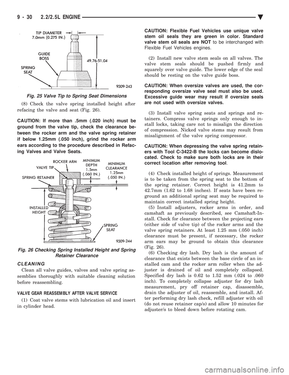
(8) Check the valve spring installed height after
refacing the valve and seat (Fig. 26).
CAUTION: If more than .5mm (.020 inch) must be
ground from the valve tip, check the clearance be-
tween the rocker arm and the valve spring retainer
if below 1.25mm (.050 inch), grind the rocker arm
ears according to the procedure described in Refac-
ing Valves and Valve Seats.
CLEANING
Clean all valve guides, valves and valve spring as-
semblies thoroughly with suitable cleaning solution
before reassembling.
VALVE GEAR REASSEMBLY AFTER VALVE SERVICE (1) Coat valve stems with lubrication oil and insert
in cylinder head. CAUTION: Flexible Fuel Vehicles use unique valve
stem oil seals they are green in color. Standard
valve stem oil seals are NOT to be interchanged with
Flexible Fuel Vehicles engines.
(2) Install new valve stem seals on all valves. The
valve stem seals should be pushed firmly and
squarely over valve guide. The lower edge of the seal
should be resting on the valve guide boss.
CAUTION: When oversize valves are used, the cor-
responding oversize valve seal must also be used.
Excessive guide wear may result if oversize seals
are not used with oversize valves.
(3) Install valve spring seats and springs and re-
tainers. Compress valve springs only enough to in-
stall locks, taking care not to misalign the direction
of compression. Nicked valve stems may result from
misalignment of the valve spring compressor.
CAUTION: When depressing the valve spring retain-
ers with Tool C-3422-B the locks can become dislo-
cated. Check to make sure both locks are in their
correct location after removing tool .
(4) Check installed height of springs. Measurement
is to be taken from the spring seat to the bottom of
the spring retainer. Correct height is 41.2mm to
42.7mm (1.62 to 1.68 inches). If seats have been re-
ground an additional spring seat may be required to
maintain correct installed spring height. (5) Install adjusters, rocker arms in order, and
camshaft as previously described, see Camshaft-In-
stall. Check for clearance between the projecting ears
(either side of valve tip) of the rocker arms and the
valve spring retainers. At least 1.25 mm (.050 inch)
clearance must be present, if necessary, the rocker
arm ears may be ground to obtain this clearance
(Fig. 26). (6) Checking dry lash. Dry lash is the amount of
clearance that exists between the base circle of an in-
stalled cam and the rocker arm roller when the ad-
juster is drained of oil and completely collapsed.
Specified dry lash is 0.62 to 1.52 mm (.024 to .060
inch). To completely collapse adjuster for dry lash
measurement, pry off retainer cap, disassemble,
drain the adjuster of oil, reassemble, and install. Af-
ter performing dry lash check, refill adjuster with oil
(do not reuse retainer cap/s) and allow 10 minutes for
adjuster/s to bleed down before rotating cam.
Fig. 25 Valve Tip to Spring Seat Dimensions
Fig. 26 Checking Spring Installed Height and Spring Retainer Clearance
9 - 30 2.2/2.5L ENGINE Ä
Page 1597 of 2438
CYLINDER HEAD AND VALVE ASSEMBLY
SERVICEÐTURBO III
CYLINDER HEAD COVER SEALING
(1) Before installation, clean cylinder head and cover
mating surfaces. Make certain rails are flat.
Caution: Do not allow oil or solvents to contact the
timing belt as they can deteriorate the rubber and
cause tooth skipping.
(2) Install covers and gasket assembly to head and
torque to 12 N Im (105 in.lbs.).
CYLINDER HEAD
REMOVAL
Refer to Intake and Exhaust Manifold Service in
Exhaust Systems and Intake Manifold Group 11 for
removal procedure for the intake and exhaust mani-
folds. (1) The Timing Belt and Solid Mount Compressor
Mount Bracket must be removed before the cylinder
head can be removed. Refer to procedure outlined in
this group for service procedures. (2) Remove cylinder head bolts.
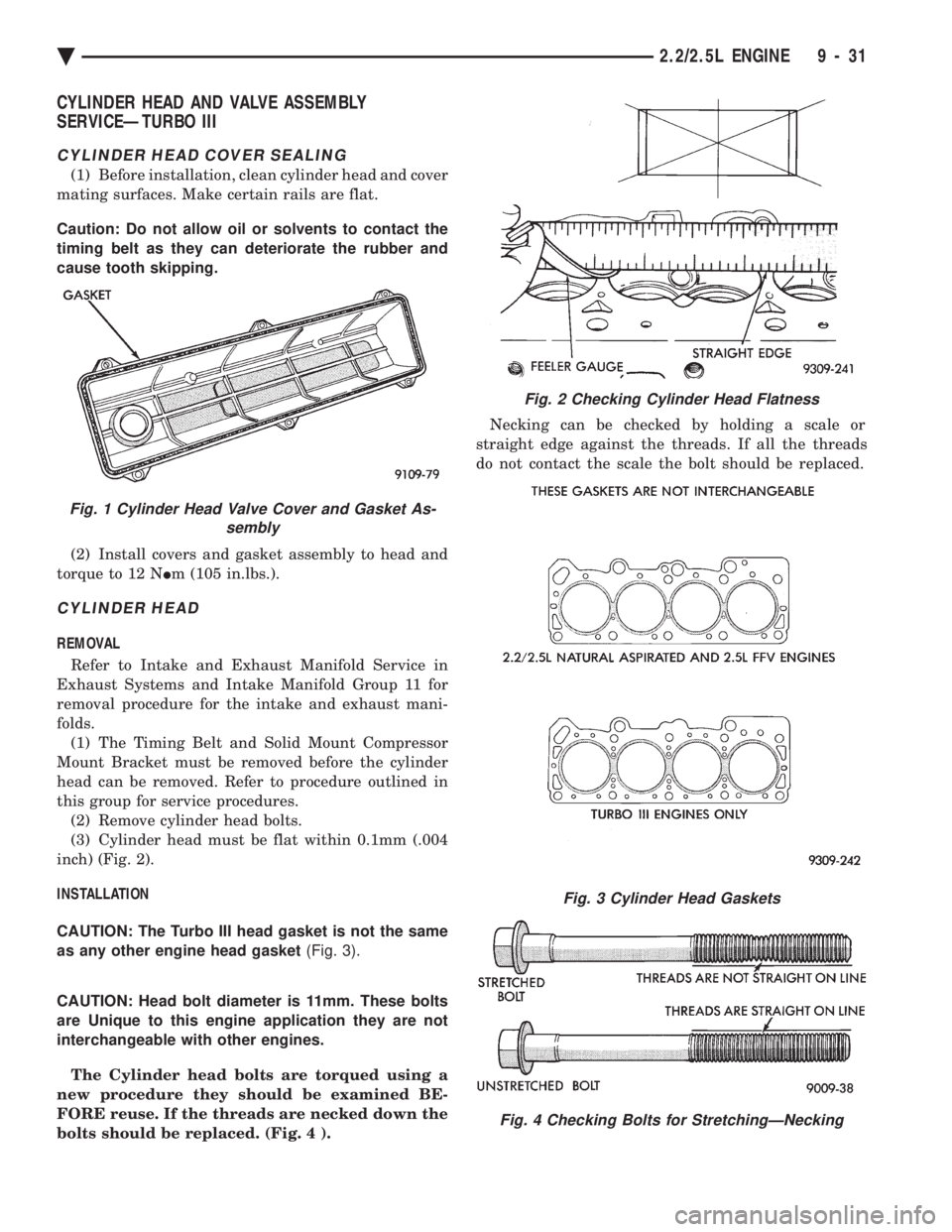
(3) Cylinder head must be flat within 0.1mm (.004
inch) (Fig. 2).
INSTALLATION
CAUTION: The Turbo III head gasket is not the same
as any other engine head gasket (Fig. 3).
CAUTION: Head bolt diameter is 11mm. These bolts
are Unique to this engine application they are not
interchangeable with other engines.
The Cylinder head bolts are torqued using a
new procedure they should be examined BE-
FORE reuse. If the threads are necked down the
bolts should be replaced. (Fig. 4 ). Necking can be checked by holding a scale or
straight edge against the threads. If all the threads
do not contact the scale the bolt should be replaced.
Fig. 2 Checking Cylinder Head Flatness
Fig. 3 Cylinder Head Gaskets
Fig. 4 Checking Bolts for StretchingÐNecking
Fig. 1 Cylinder Head Valve Cover and Gasket As- sembly
Ä 2.2/2.5L ENGINE 9 - 31
Page 1603 of 2438
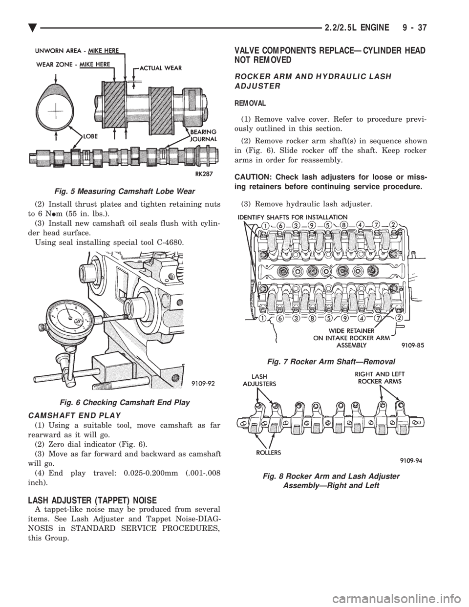
(2) Install thrust plates and tighten retaining nuts
to6N Im (55 in. lbs.).
(3) Install new camshaft oil seals flush with cylin-
der head surface. Using seal installing special tool C-4680.
CAMSHAFT END PLAY
(1) Using a suitable tool, move camshaft as far
rearward as it will go. (2) Zero dial indicator (Fig. 6).
(3) Move as far forward and backward as camshaft
will go. (4) End play travel: 0.025-0.200mm (.001-.008
inch).
LASH ADJUSTER (TAPPET) NOISE
A tappet-like noise may be produced from several
items. See Lash Adjuster and Tappet Noise-DIAG-
NOSIS in STANDARD SERVICE PROCEDURES,
this Group.
VALVE COMPONENTS REPLACEÐCYLINDER HEAD
NOT REMOVED
ROCKER ARM AND HYDRAULIC LASH
ADJUSTER
REMOVAL
(1) Remove valve cover. Refer to procedure previ-
ously outlined in this section.
(2) Remove rocker arm shaft(s) in sequence shown
in (Fig. 6). Slide rocker off the shaft. Keep rocker
arms in order for reassembly.
CAUTION: Check lash adjusters for loose or miss-
ing retainers before continuing service procedure.
(3) Remove hydraulic lash adjuster.
Fig. 5 Measuring Camshaft Lobe Wear
Fig. 6 Checking Camshaft End Play
Fig. 7 Rocker Arm ShaftÐRemoval
Fig. 8 Rocker Arm and Lash Adjuster AssemblyÐRight and Left
Ä 2.2/2.5L ENGINE 9 - 37
Page 1606 of 2438
VALVE GEAR REASSEMBLY AFTER VALVE SERVICE
(1) Coat valve stems with lubrication oil and insert
in cylinder head. (2) Install new valve stem seals on all valves. The
valve stem seals should be pushed firmly and
squarely over valve guide. The lower edge of the seal
should be resting on the valve guide boss. (3) Install valve spring seats and springs and re-
tainers. Compress valve springs only enough to in-
stall locks, taking care not to misalign the direction
of compression. Nicked valve stems may result from
misalignment of the valve spring compressor.
CAUTION: When depressing the valve spring retain-
ers with Valve Spring Compressor Tool C-3422-B
with adopters 6537 and 6526 (Fig. 11) the locks can
become dislocated. Check to make sure both locks
are in their correct location after removing tool.
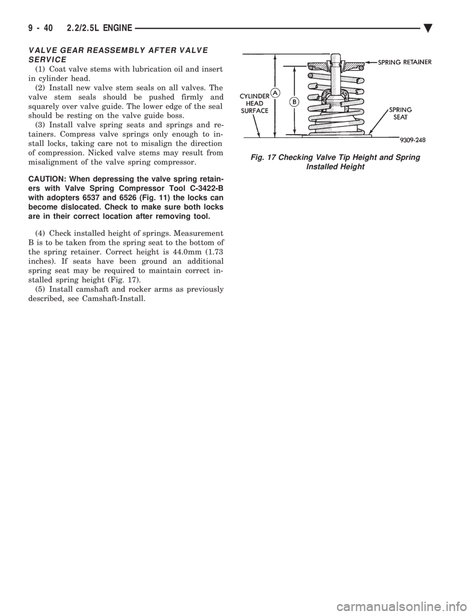
(4) Check installed height of springs. Measurement
B is to be taken from the spring seat to the bottom of
the spring retainer. Correct height is 44.0mm (1.73
inches). If seats have been ground an additional
spring seat may be required to maintain correct in-
stalled spring height (Fig. 17). (5) Install camshaft and rocker arms as previously
described, see Camshaft-Install.
Fig. 17 Checking Valve Tip Height and Spring Installed Height
9 - 40 2.2/2.5L ENGINE Ä
Page 1609 of 2438
CRANKSHAFT SERVICE
CRANKSHAFT MAIN BEARINGS
Bearing caps are not interchangeable and should
be marked at removal to insure correct assembly.
Upper and lower bearing halves are NOT inter-
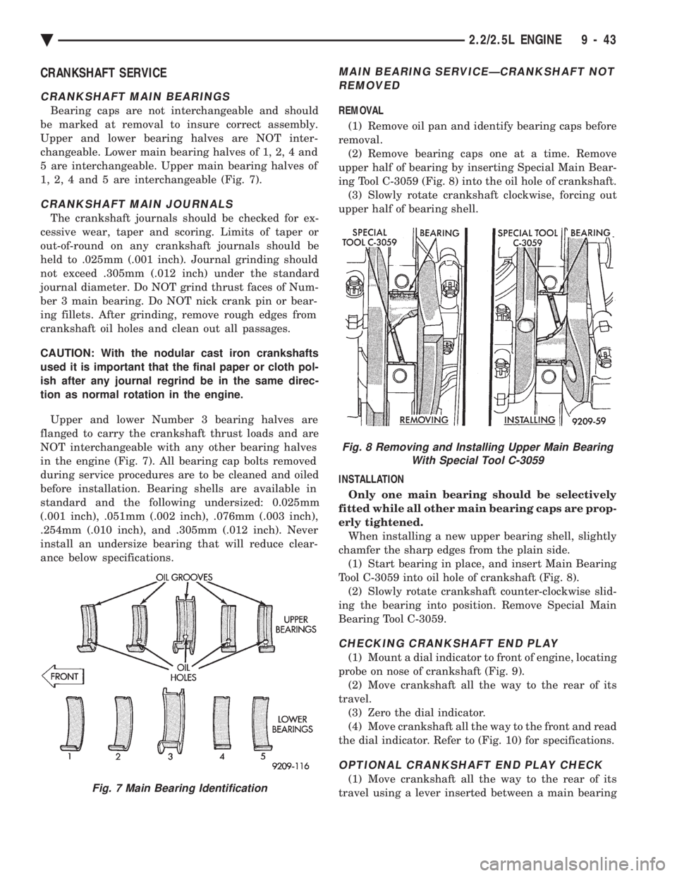
changeable. Lower main bearing halves of 1, 2, 4 and
5 are interchangeable. Upper main bearing halves of
1, 2, 4 and 5 are interchangeable (Fig. 7).
CRANKSHAFT MAIN JOURNALS
The crankshaft journals should be checked for ex-
cessive wear, taper and scoring. Limits of taper or
out-of-round on any crankshaft journals should be
held to .025mm (.001 inch). Journal grinding should
not exceed .305mm (.012 inch) under the standard
journal diameter. Do NOT grind thrust faces of Num-
ber 3 main bearing. Do NOT nick crank pin or bear-
ing fillets. After grinding, remove rough edges from
crankshaft oil holes and clean out all passages.
CAUTION: With the nodular cast iron crankshafts
used it is important that the final paper or cloth pol-
ish after any journal regrind be in the same direc-
tion as normal rotation in the engine.
Upper and lower Number 3 bearing halves are
flanged to carry the crankshaft thrust loads and are
NOT interchangeable with any other bearing halves
in the engine (Fig. 7). All bearing cap bolts removed
during service procedures are to be cleaned and oiled
before installation. Bearing shells are available in
standard and the following undersized: 0.025mm
(.001 inch), .051mm (.002 inch), .076mm (.003 inch),
.254mm (.010 inch), and .305mm (.012 inch). Never
install an undersize bearing that will reduce clear-
ance below specifications.
MAIN BEARING SERVICEÐCRANKSHAFT NOT REMOVED
REMOVAL
(1) Remove oil pan and identify bearing caps before
removal. (2) Remove bearing caps one at a time. Remove
upper half of bearing by inserting Special Main Bear-
ing Tool C-3059 (Fig. 8) into the oil hole of crankshaft. (3) Slowly rotate crankshaft clockwise, forcing out
upper half of bearing shell.
INSTALLATION Only one main bearing should be selectively
fitted while all other main bearing caps are prop-
erly tightened. When installing a new upper bearing shell, slightly
chamfer the sharp edges from the plain side. (1) Start bearing in place, and insert Main Bearing
Tool C-3059 into oil hole of crankshaft (Fig. 8). (2) Slowly rotate crankshaft counter-clockwise slid-
ing the bearing into position. Remove Special Main
Bearing Tool C-3059.
CHECKING CRANKSHAFT END PLAY
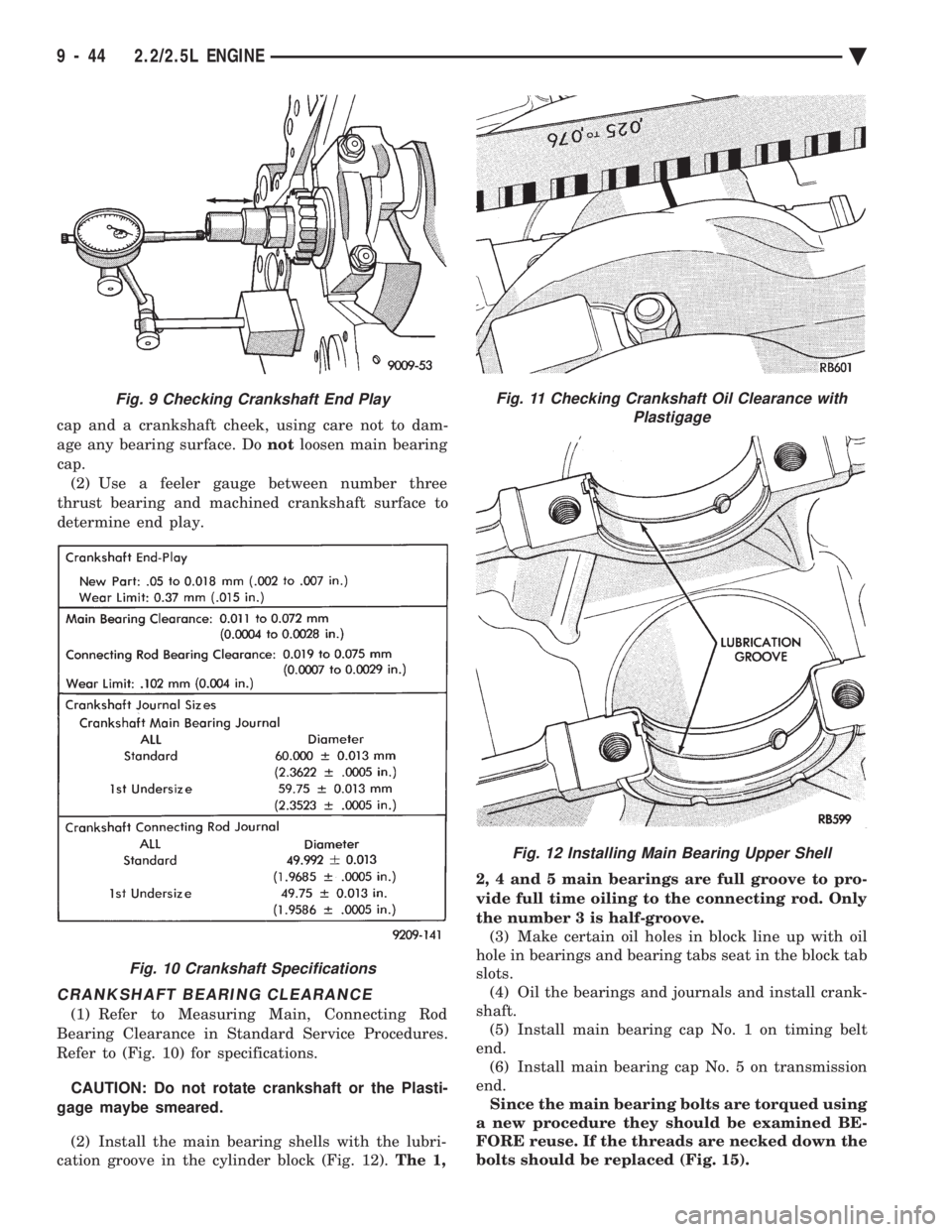
(1) Mount a dial indicator to front of engine, locating
probe on nose of crankshaft (Fig. 9). (2) Move crankshaft all the way to the rear of its
travel. (3) Zero the dial indicator.
(4) Move crankshaft all the way to the front and read
the dial indicator. Refer to (Fig. 10) for specifications.
OPTIONAL CRANKSHAFT END PLAY CHECK
(1) Move crankshaft all the way to the rear of its
travel using a lever inserted between a main bearingFig. 7 Main Bearing Identification
Fig. 8 Removing and Installing Upper Main Bearing With Special Tool C-3059
Ä 2.2/2.5L ENGINE 9 - 43
Page 1610 of 2438
cap and a crankshaft cheek, using care not to dam-
age any bearing surface. Do notloosen main bearing
cap. (2) Use a feeler gauge between number three
thrust bearing and machined crankshaft surface to
determine end play.
CRANKSHAFT BEARING CLEARANCE
(1) Refer to Measuring Main, Connecting Rod
Bearing Clearance in Standard Service Procedures.
Refer to (Fig. 10) for specifications.
CAUTION: Do not rotate crankshaft or the Plasti-
gage maybe smeared.
(2) Install the main bearing shells with the lubri-
cation groove in the cylinder block (Fig. 12). The 1, 2, 4 and 5 main bearings are full groove to pro-
vide full time oiling to the connecting rod. Only
the number 3 is half-groove.
(3) Make certain oil holes in block line up with oil
hole in bearings and bearing tabs seat in the block tab
slots. (4) Oil the bearings and journals and install crank-
shaft. (5) Install main bearing cap No. 1 on timing belt
end. (6) Install main bearing cap No. 5 on transmission
end. Since the main bearing bolts are torqued using
a new procedure they should be examined BE-
FORE reuse. If the threads are necked down the
bolts should be replaced (Fig. 15).
Fig. 9 Checking Crankshaft End Play
Fig. 10 Crankshaft Specifications
Fig. 11 Checking Crankshaft Oil Clearance with Plastigage
Fig. 12 Installing Main Bearing Upper Shell
9 - 44 2.2/2.5L ENGINE Ä