1993 CHEVROLET DYNASTY checking oil
[x] Cancel search: checking oilPage 1934 of 2438
(15) Start engine and turn steering wheel several
times from stop to stop to bleed air from fluid in sys-
tem. Stop engine, check fluid level, and inspect sys-
tem for leaks. See Checking Fluid Level.
3.3 & 3.8 LITER
REMOVE
(1) Remove the (-) negative battery cable from the
battery and isolate cable. (2) Remove the serpentine accessory drive belt
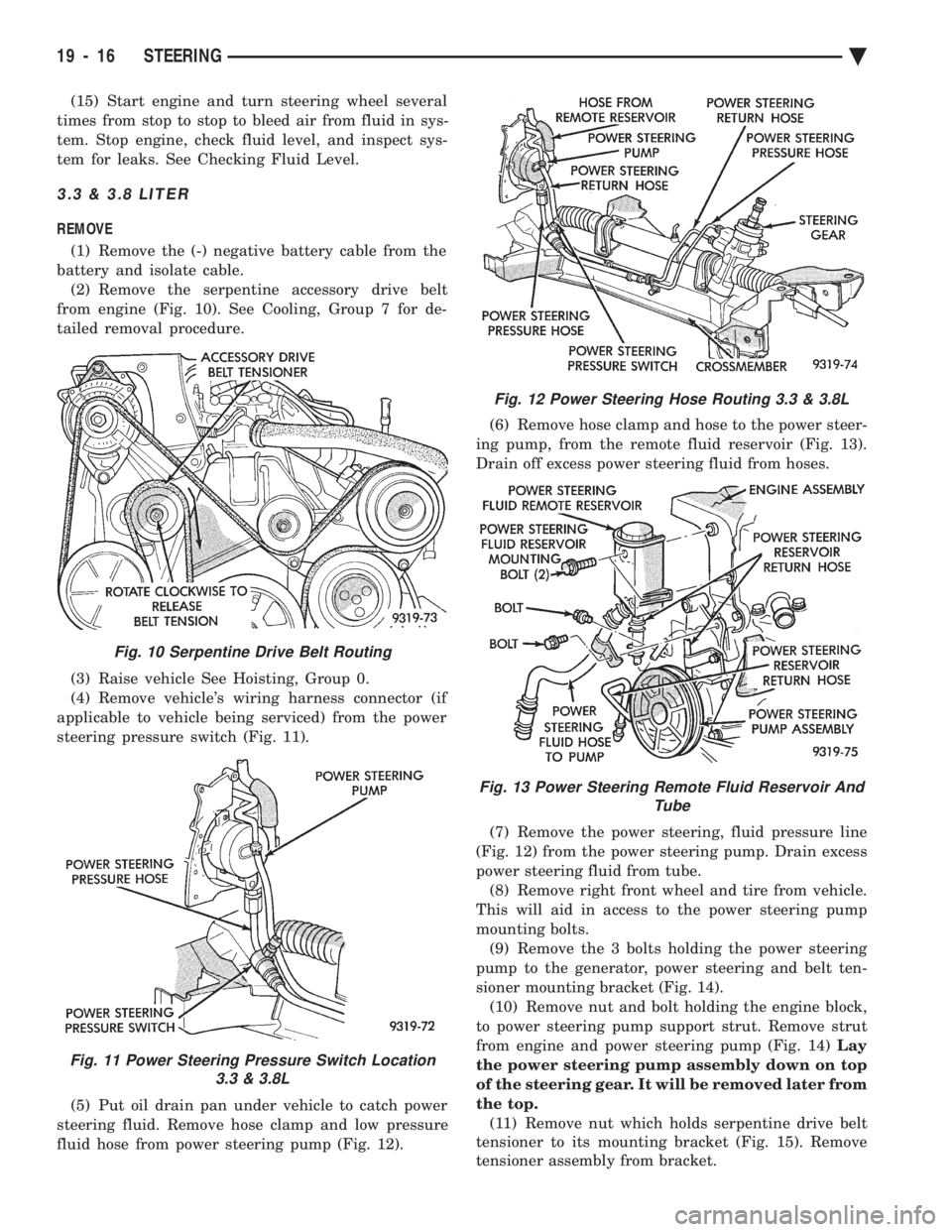
from engine (Fig. 10). See Cooling, Group 7 for de-
tailed removal procedure.
(3) Raise vehicle See Hoisting, Group 0.
(4) Remove vehicle's wiring harness connector (if
applicable to vehicle being serviced) from the power
steering pressure switch (Fig. 11).
(5) Put oil drain pan under vehicle to catch power
steering fluid. Remove hose clamp and low pressure
fluid hose from power steering pump (Fig. 12). (6) Remove hose clamp and hose to the power steer-
ing pump, from the remote fluid reservoir (Fig. 13).
Drain off excess power steering fluid from hoses.
(7) Remove the power steering, fluid pressure line
(Fig. 12) from the power steering pump. Drain excess
power steering fluid from tube. (8) Remove right front wheel and tire from vehicle.
This will aid in access to the power steering pump
mounting bolts. (9) Remove the 3 bolts holding the power steering
pump to the generator, power steering and belt ten-
sioner mounting bracket (Fig. 14). (10) Remove nut and bolt holding the engine block,
to power steering pump support strut. Remove strut
from engine and power steering pump (Fig. 14) Lay
the power steering pump assembly down on top
of the steering gear. It will be removed later from
the top. (11) Remove nut which holds serpentine drive belt
tensioner to its mounting bracket (Fig. 15). Remove
tensioner assembly from bracket.
Fig. 10 Serpentine Drive Belt Routing
Fig. 11 Power Steering Pressure Switch Location 3.3 & 3.8L
Fig. 12 Power Steering Hose Routing 3.3 & 3.8L
Fig. 13 Power Steering Remote Fluid Reservoir And Tube
19 - 16 STEERING Ä
Page 1937 of 2438
(18) Lower vehicle.
(19) Install the serpentine drive belt. Refer to (Fig.
10) for correct serpentine belt routing. See Cooling,
Group 7 for detailed installation procedure.
CAUTION: Do not use automatic transmission fluid
in power steering system. Only use Mopar T, Power
Steering Fluid, or equivalent.
(20) Fill power steering pump reservoir to correct
fluid level. (21) Connect the negative battery cable on the
negative battery post. (22) Start engine and turn steering wheel several
times from stop to stop to bleed air from fluid in sys-
tem. Stop engine, check fluid level, and inspect sys-
tem for leaks. See Checking Fluid Level.
TURBO III
REMOVE
(1) Disconnect the battery (-) negative cable from
the battery and isolate cable. (2) Raise vehicle See Hoisting, Group 0. Put oil
drain pan under vehicle to catch power steering
fluid. (3) Remove the right front underhood splash shield
for access to the serpentine belt tensioner. (4) Release the tension on the serpentine drive belt
tensioner and remove drive belt from power steering
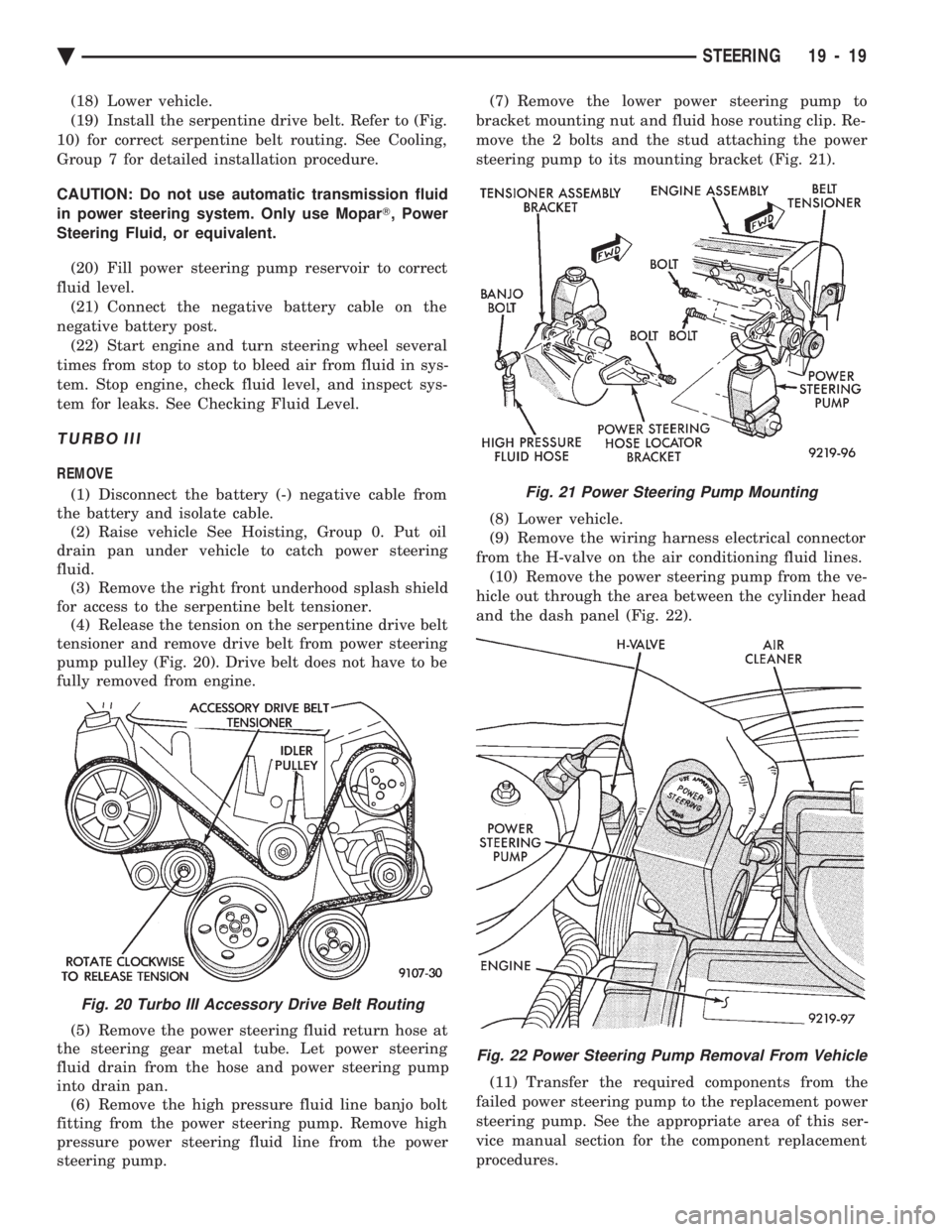
pump pulley (Fig. 20). Drive belt does not have to be
fully removed from engine.
(5) Remove the power steering fluid return hose at
the steering gear metal tube. Let power steering
fluid drain from the hose and power steering pump
into drain pan. (6) Remove the high pressure fluid line banjo bolt
fitting from the power steering pump. Remove high
pressure power steering fluid line from the power
steering pump. (7) Remove the lower power steering pump to
bracket mounting nut and fluid hose routing clip. Re-
move the 2 bolts and the stud attaching the power
steering pump to its mounting bracket (Fig. 21).
(8) Lower vehicle.
(9) Remove the wiring harness electrical connector
from the H-valve on the air conditioning fluid lines. (10) Remove the power steering pump from the ve-
hicle out through the area between the cylinder head
and the dash panel (Fig. 22).
(11) Transfer the required components from the
failed power steering pump to the replacement power
steering pump. See the appropriate area of this ser-
vice manual section for the component replacement
procedures.
Fig. 20 Turbo III Accessory Drive Belt Routing
Fig. 21 Power Steering Pump Mounting
Fig. 22 Power Steering Pump Removal From Vehicle
Ä STEERING 19 - 19
Page 1992 of 2438
ing seat will give a false end play reading while
gauging for proper shims. Improperly seated bearing
cups and cones are subject to low mileage failure.(2) Bearing cups and cones should be replaced if they
show signs of pitting or heat distress. If distress is seen
on either the cup or bearing rollers, both cup and cone
must be replaced. (3) Bearing preload and drag torque specifications
must be maintained to avoid premature bearing
failures. Used (original) bearing may lose up to 50% of
the original drag torque after break in. All bearing
adjustments must be made with no other compo-
nent interference or gear intermesh. (4) Replace bearings as a pair. For example, if one
differential bearing is defective, replace both differen-
tial bearings. If one input shaft bearing is defective,
replace both input shaft bearings. (5) Bearing cones must notbe reused if removed.
(6) Turning torque readings should be obtained
while smoothly rotating in either direction (break-
away reading is not indicative of the true turning
torque). (7) Replace oil baffle, if damaged.
INPUT SHAFT BEARING END PLAY ADJUST-MENT
(1) Using Tool C-4656 with Handle C-4171, press
input shaft front bearing cup slightly forward in case.
Then, using Tool C-4655 with Handle C-4171, press
bearing cup back into case from the front. Properly
position bearing cup, before checking input shaft end
play (see input shaft front bearing cup replace in
Subassembly Recondition section).This step is
not necessary if Tool C-4655 was previously used
to install input shaft front bearing cup in the
case. Also no input shaft shim has been installed
since pressing cup into case. (2) Select a gauging shim which will give 0.025 to
0.254mm (.001 to .010 inch) end play. SUGGESTION:
Measure original shim from input shaft seal retainer and select a shim 0.254mm (.010
inch) thinner than original for the gauging shim.
(3) Install gauging shim on bearing cup and install
input shaft seal retainer.
CAUTION: The input shaft seal retainer is used to
draw the input shaft front bearing cup the proper
distance into the case bore during this step. Alter-
nately tighten input shaft seal retainer bolts until
input shaft seal retainer is bottomed against case.
Tighten bolts to 28 N Im (21 ft. lbs.).
(4) Oil input shaft bearings with SAE 5W-30 engine
oil and install input shaft in case. Install bearing
retainer plate with input shaft rear bearing cup
pressed in and bearing support plate installed. Tighten
all bolts and nuts to 28 N Im (21 ft. lbs.).
(5) Position dial indicator to check input shaft end
play. Apply moderate load, by hand, to input shaft
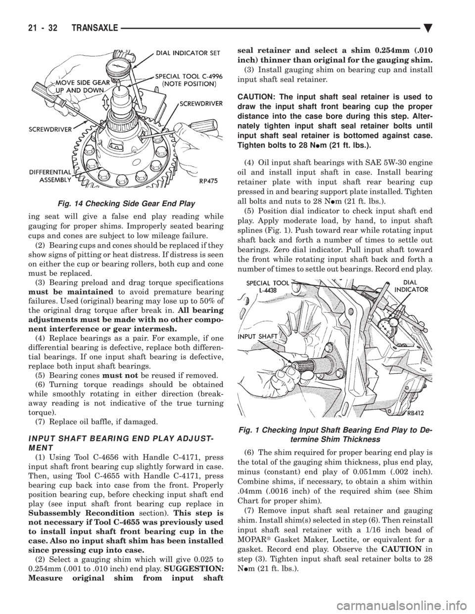
splines (Fig. 1). Push toward rear while rotating input
shaft back and forth a number of times to settle out
bearings. Zero dial indicator. Pull input shaft toward
the front while rotating input shaft back and forth a
number of times to settle out bearings. Record end play.
(6) The shim required for proper bearing end play is
the total of the gauging shim thickness, plus end play,
minus (constant) end play of 0.051mm (.002 inch).
Combine shims, if necessary, to obtain a shim within
.04mm (.0016 inch) of the required shim (see Shim
Chart for proper shim). (7) Remove input shaft seal retainer and gauging
shim. Install shim(s) selected in step (6). Then reinstall
input shaft seal retainer with a 1/16 inch bead of
MOPAR tGasket Maker, Loctite, or equivalent for a
gasket. Record end play. Observe the CAUTIONin
step (3). Tighten input shaft seal retainer bolts to 28
N Im (21 ft. lbs.).
Fig. 14 Checking Side Gear End Play
Fig. 1 Checking Input Shaft Bearing End Play to De-
termine Shim Thickness
21 - 32 TRANSAXLE Ä
Page 1993 of 2438
(8) Verify that a preload condition does not exist.
Use Special Tool L-4508 and an inch-pound torque
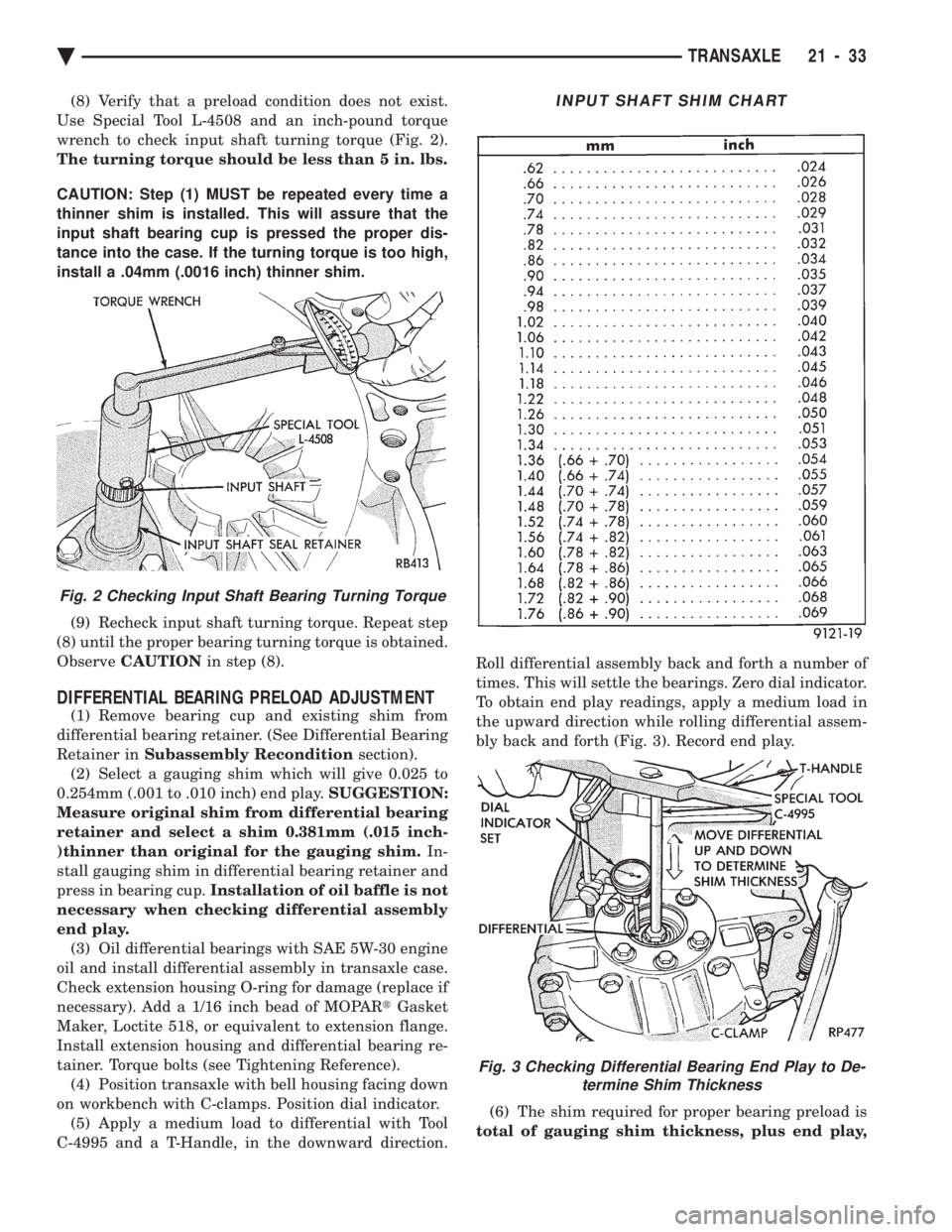
wrench to check input shaft turning torque (Fig. 2).
The turning torque should be less than 5 in. lbs.
CAUTION: Step (1) MUST be repeated every time a
thinner shim is installed. This will assure that the
input shaft bearing cup is pressed the proper dis-
tance into the case. If the turning torque is too high,
install a .04mm (.0016 inch) thinner shim.
(9) Recheck input shaft turning torque. Repeat step
(8) until the proper bearing turning torque is obtained.
Observe CAUTION in step (8).
DIFFERENTIAL BEARING PRELOAD ADJUSTMENT
(1) Remove bearing cup and existing shim from
differential bearing retainer. (See Differential Bearing
Retainer in Subassembly Recondition section).
(2) Select a gauging shim which will give 0.025 to
0.254mm (.001 to .010 inch) end play. SUGGESTION:
Measure original shim from differential bearing
retainer and select a shim 0.381mm (.015 inch-
)thinner than original for the gauging shim. In-
stall gauging shim in differential bearing retainer and
press in bearing cup. Installation of oil baffle is not
necessary when checking differential assembly
end play. (3) Oil differential bearings with SAE 5W-30 engine
oil and install differential assembly in transaxle case.
Check extension housing O-ring for damage (replace if
necessary). Add a 1/16 inch bead of MOPAR tGasket
Maker, Loctite 518, or equivalent to extension flange.
Install extension housing and differential bearing re-
tainer. Torque bolts (see Tightening Reference). (4) Position transaxle with bell housing facing down
on workbench with C-clamps. Position dial indicator. (5) Apply a medium load to differential with Tool
C-4995 and a T-Handle, in the downward direction. Roll differential assembly back and forth a number of
times. This will settle the bearings. Zero dial indicator.
To obtain end play readings, apply a medium load in
the upward direction while rolling differential assem-
bly back and forth (Fig. 3). Record end play.
(6) The shim required for proper bearing preload is
total of gauging shim thickness, plus end play,
Fig. 2 Checking Input Shaft Bearing Turning Torque
INPUT SHAFT SHIM CHART
Fig. 3 Checking Differential Bearing End Play to De- termine Shim Thickness
Ä TRANSAXLE 21 - 33
Page 1994 of 2438
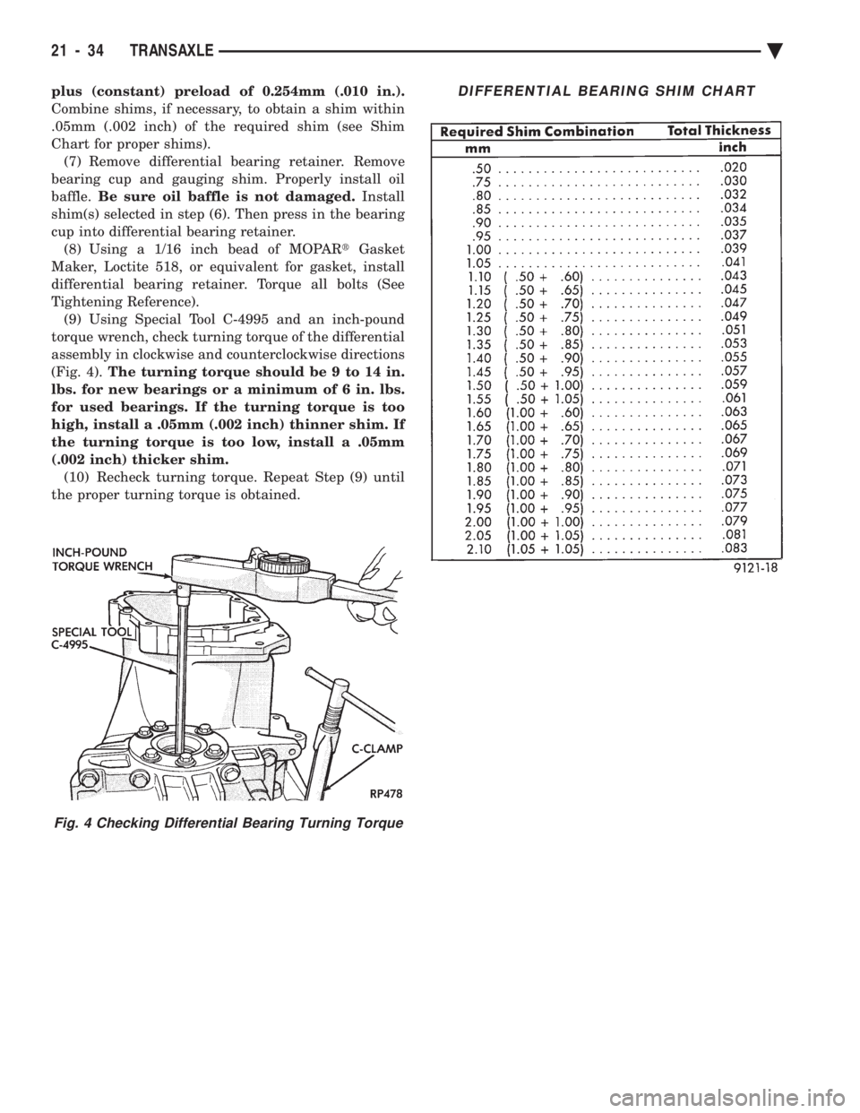
plus (constant) preload of 0.254mm (.010 in.).
Combine shims, if necessary, to obtain a shim within
.05mm (.002 inch) of the required shim (see Shim
Chart for proper shims).(7) Remove differential bearing retainer. Remove
bearing cup and gauging shim. Properly install oil
baffle. Be sure oil baffle is not damaged. Install
shim(s) selected in step (6). Then press in the bearing
cup into differential bearing retainer. (8) Using a 1/16 inch bead of MOPAR tGasket
Maker, Loctite 518, or equivalent for gasket, install
differential bearing retainer. Torque all bolts (See
Tightening Reference). (9) Using Special Tool C-4995 and an inch-pound
torque wrench, check turning torque of the differential
assembly in clockwise and counterclockwise directions
(Fig. 4). The turning torque should be 9 to 14 in.
lbs. for new bearings or a minimum of 6 in. lbs.
for used bearings. If the turning torque is too
high, install a .05mm (.002 inch) thinner shim. If
the turning torque is too low, install a .05mm
(.002 inch) thicker shim. (10) Recheck turning torque. Repeat Step (9) until
the proper turning torque is obtained.
Fig. 4 Checking Differential Bearing Turning Torque
DIFFERENTIAL BEARING SHIM CHART
21 - 34 TRANSAXLE Ä
Page 1996 of 2438
TORQUE CONVERTER CLUTCH
The torque converter clutch is standard on all ve-
hicles. It is activated only in direct drive and is con-
trolled by the engine electronics. A solenoid on the
valve body, is powered by the powertrain control mod-
ule to activate torque converter clutch.
HYDRAULIC CONTROL SYSTEM
The hydraulic control circuits show the position of
the various valves. They indicate those under hydrau-
lic pressure for all operations of the transaxle. The hydraulic control system makes the transaxle
fully automatic, and has four important functions to
perform. In a general way, the components of any
automatic control system may be grouped into the
following basic groups: The pressure supply system, the pressure regulating
valves, the flow control valves, the clutches, and band
servos. Taking each of these basic groups or systems in turn,
the control system may be described as follows:
PRESSURE SUPPLY SYSTEM
The pressure supply system consists of an oil pump
driven by the engine through the torque converter. The
single pump furnishes pressure for all the hydraulic
and lubrication requirements. Oil pump housing
assemblies are available with preselected pump
gears.
PRESSURE REGULATING VALVES
The pressure regulating valve controls line pressure
dependent on throttle opening. The governor valve
transmits regulated pressure to the valve body (in
conjunction with vehicle speed) to control upshift and
downshift. The throttle valve transmits regulated pressure to
the transaxle (dependent on throttle position) to con-
trol upshift and downshift.
FLOW CONTROL VALVES
The manual valve provides the different transaxle
drive ranges as selected by the vehicle operator. The 1-2 shift valve automatically shifts the transaxle
from first to second or from second to first, depending
on the vehicle operation. The 2-3 shift valve automatically shifts the transaxle
from second to third or from third to second depending
on the vehicle operation. The kickdown valve makes possible a forced down-
shift from third to second, second to first, or third to
first (depending on vehicle speed). This can be done by
depressing the accelerator pedal past the detent ``feel''
near wide open throttle. The shuttle valve has two separate functions and
performs each independently of the other. The first
provides fast release of the kickdown band, and
smooth front clutch engagement, when the driver makes a
lift-footupshift from second to third. The
second function of the shuttle valve is to regulate the
application of the kickdown servo and band when
making third to second kickdown. The by-pass valve provides for smooth application of
the kickdown band on 1-2 upshifts. The torque converter clutch solenoid allows for the
electronic control of the clutch inside the torque con-
verter. It also disengages the torque converter at closed
throttle, during engine warm-up, and during part-
throttle acceleration. The switch valve directs oil to apply the torque
converter clutch in one position and releases the torque
converter clutch in the other position.
CLUTCH, BAND SERVO, AND ACCUMULATOR
The front and rear clutch pistons, and both servo
pistons are moved hydraulically to engage the clutches
and apply the bands. The pistons are released by
spring tension when hydraulic pressure is released. On
the 2-3 upshift, the kickdown servo piston is released
by spring tension and hydraulic pressure. The accumulator controls the hydraulic pressure on
the apply side of the kickdown servo during the 1-2
upshift; thereby, cushioning the kickdown band appli-
cation at any throttle position.
GEARSHIFT AND PARKING LOCK CONTROLS
The transaxle is controlled by a lever typegearshift
incorporated within the console or the steering column.
The control has six selector lever positions: P (park), R
(reverse), N (neutral), and D (drive), 2 (second), and 1
(first). The parking lock is applied by moving the
selector lever past a gate to the Pposition. Do not
apply the parking lock until the vehicle has
stopped; otherwise, a severe banging noise will
occur.
THREE SPEED TORQUEFLITE GENERAL DIAGNO-
SIS
Automatic transaxle malfunctions may be caused by
four general conditions:
² Poor engine performance
² Improper adjustments
² Hydraulic malfunctions
² Mechanical malfunctions.
Diagnosis of these problems should always begin by
checking the easily accessible variables: fluid level and
condition, gearshift cable adjustment, and throttle
pressure cable adjustment. Then perform a road test to
determine if the problem has been corrected or that
more diagnosis is necessary. If the problem exists after
the preliminary tests and corrections are completed,
hydraulic pressure tests should be performed.
21 - 36 TRANSAXLE Ä
Page 2058 of 2438
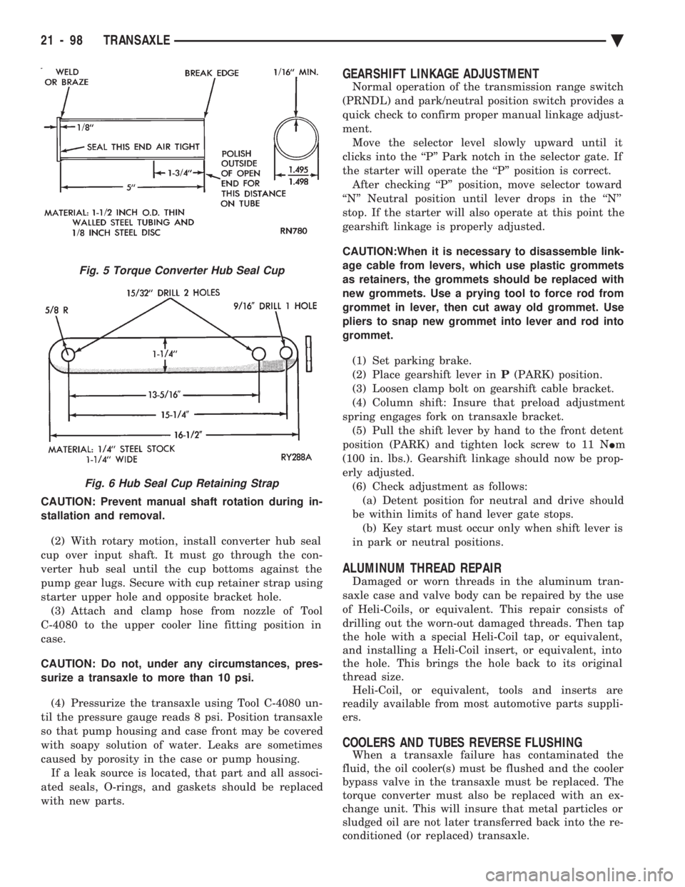
CAUTION: Prevent manual shaft rotation during in-
stallation and removal. (2) With rotary motion, install converter hub seal
cup over input shaft. It must go through the con-
verter hub seal until the cup bottoms against the
pump gear lugs. Secure with cup retainer strap using
starter upper hole and opposite bracket hole. (3) Attach and clamp hose from nozzle of Tool
C-4080 to the upper cooler line fitting position in
case.
CAUTION: Do not, under any circumstances, pres-
surize a transaxle to more than 10 psi.
(4) Pressurize the transaxle using Tool C-4080 un-
til the pressure gauge reads 8 psi. Position transaxle
so that pump housing and case front may be covered
with soapy solution of water. Leaks are sometimes
caused by porosity in the case or pump housing. If a leak source is located, that part and all associ-
ated seals, O-rings, and gaskets should be replaced
with new parts.
GEARSHIFT LINKAGE ADJUSTMENT
Normal operation of the transmission range switch
(PRNDL) and park/neutral position switch provides a
quick check to confirm proper manual linkage adjust-
ment. Move the selector level slowly upward until it
clicks into the ``P'' Park notch in the selector gate. If
the starter will operate the ``P'' position is correct. After checking ``P'' position, move selector toward
``N'' Neutral position until lever drops in the ``N''
stop. If the starter will also operate at this point the
gearshift linkage is properly adjusted.
CAUTION:When it is necessary to disassemble link-
age cable from levers, which use plastic grommets
as retainers, the grommets should be replaced with
new grommets. Use a prying tool to force rod from
grommet in lever, then cut away old grommet. Use
pliers to snap new grommet into lever and rod into
grommet.
(1) Set parking brake.
(2) Place gearshift lever in P(PARK) position.
(3) Loosen clamp bolt on gearshift cable bracket.
(4) Column shift: Insure that preload adjustment
spring engages fork on transaxle bracket. (5) Pull the shift lever by hand to the front detent
position (PARK) and tighten lock screw to 11 N Im
(100 in. lbs.). Gearshift linkage should now be prop-
erly adjusted. (6) Check adjustment as follows:(a) Detent position for neutral and drive should
be within limits of hand lever gate stops. (b) Key start must occur only when shift lever is
in park or neutral positions.
ALUMINUM THREAD REPAIR
Damaged or worn threads in the aluminum tran-
saxle case and valve body can be repaired by the use
of Heli-Coils, or equivalent. This repair consists of
drilling out the worn-out damaged threads. Then tap
the hole with a special Heli-Coil tap, or equivalent,
and installing a Heli-Coil insert, or equivalent, into
the hole. This brings the hole back to its original
thread size. Heli-Coil, or equivalent, tools and inserts are
readily available from most automotive parts suppli-
ers.
COOLERS AND TUBES REVERSE FLUSHING
When a transaxle failure has contaminated the
fluid, the oil cooler(s) must be flushed and the cooler
bypass valve in the transaxle must be replaced. The
torque converter must also be replaced with an ex-
change unit. This will insure that metal particles or
sludged oil are not later transferred back into the re-
conditioned (or replaced) transaxle.
Fig. 5 Torque Converter Hub Seal Cup
Fig. 6 Hub Seal Cup Retaining Strap
21 - 98 TRANSAXLE Ä
Page 2092 of 2438
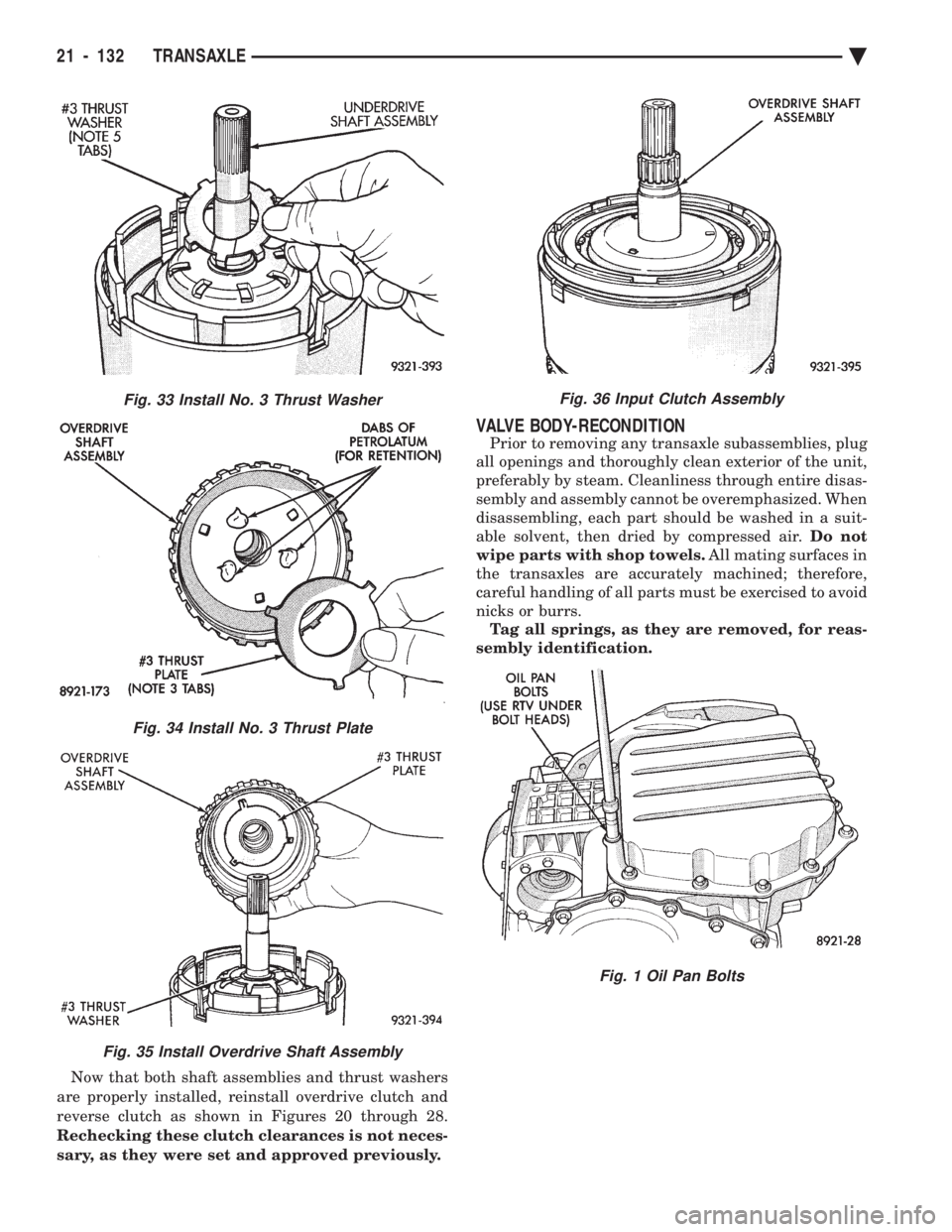
Now that both shaft assemblies and thrust washers
are properly installed, reinstall overdrive clutch and
reverse clutch as shown in Figures 20 through 28.
Rechecking these clutch clearances is not neces-
sary, as they were set and approved previously.
VALVE BODY-RECONDITION
Prior to removing any transaxle subassemblies, plug
all openings and thoroughly clean exterior of the unit,
preferably by steam. Cleanliness through entire disas-
sembly and assembly cannot be overemphasized. When
disassembling, each part should be washed in a suit-
able solvent, then dried by compressed air. Do not
wipe parts with shop towels. All mating surfaces in
the transaxles are accurately machined; therefore,
careful handling of all parts must be exercised to avoid
nicks or burrs. Tag all springs, as they are removed, for reas-
sembly identification.
Fig. 33 Install No. 3 Thrust Washer
Fig. 34 Install No. 3 Thrust Plate
Fig. 35 Install Overdrive Shaft Assembly
Fig. 36 Input Clutch Assembly
Fig. 1 Oil Pan Bolts
21 - 132 TRANSAXLE Ä