1993 CHEVROLET DYNASTY open hood
[x] Cancel search: open hoodPage 40 of 2438

LUBRICANTS AND GREASES
Lubricating grease is rated for quality and usage
by the NLGI. All approved products have the NLGI
symbol on the label. At the bottom NLGI symbol is the usage and qual-
ity identification letters. Wheel bearing lubricant is
identified by the letter ``G''. Chassis lubricant is iden-
tified by the letter ``L''. The letter following the us-
age letter indicates the quality of the lubricant. The
following symbols indicate the highest quality.
FLUID CAPACITIES
Fuel Tank
AP,AG and AJ ......................................53 L (14 gal.)
AA,AC and AY .....................................60 L (16 gal.)
AA-Flexible Fuel ..................................68 L (18 gal.)
Engine Oil
All.........................................................3.8 L (4.5 qts.)
Cooling System
2.2L ......................................................8.5 L (9.0 qts.)
2.5L ......................................................8.5 L (9.0 qts.)
3.0L ......................................................9.0 L (9.5 qts.)
3.3L ......................................................9.0 L (9.5 qts.)
3.8L ......................................................9.0 L (9.5 qts.)
Includes heater and coolant recovery bottle
Automatic Transaxle
Estimated Service Fill
ALL ......................................................3.8 L (4.0 qts.)
Overhaul Fill Capacity with Torque Converter
Empty
3-speed Fleet .......................................8.7 L (9.2 qts.)
3-speed .................................................8.2 L (8.8 qts.)
4-speed Electronic ................................9.4L (9.9 qts.)
Manual Transaxle
All ..........................................................9.4L (9.9 qts.)
Fill to bottom of fill hole.
Power Steering
All ...........................................................75L (1.5 pts.)
PARTS REQUIRING NO LUBRICATION
Many components on a Chrysler Corporation vehi-
cle require no periodic maintenance. Some compo-
nents are sealed and permanently lubricated. Rubber
bushings can deteriorate or limit damping ability if
lubricated. The following list of components require
no lubrication: ²
Air Pump
² Generator Bushings
² Drive Belts
² Drive Belt Idler/Tensioner Pulley
² Front Wheel Bearings
² Rubber Bushings
² Starter Bearings/Bushings
² Suspension Strut Bearings
² Throttle Control Cable
² Throttle Linkage
² Water Pump Bearings
JUMP STARTING PROCEDURE
WARNING: REVIEW ALL SAFETY PRECAUTIONS
AND WARNINGS IN GROUP 8A, BATTERY/START-
ING/CHARGING SYSTEMS DIAGNOSTICS. DO NOT JUMP START A FROZEN BATTERY, PER-
SONAL INJURY CAN RESULT. DO NOT JUMP START WHEN BATTERY INDICA-
TOR DOT IS YELLOW OR BRIGHT COLOR. DO NOT ALLOW JUMPER CABLE CLAMPS TO
TOUCH EACH OTHER WHEN CONNECTED TO A
BOOSTER SOURCE. DO NOT USE OPEN FLAME NEAR BATTERY.
REMOVE METALLIC JEWELRY WORN ON HANDS
OR WRISTS TO AVOID INJURY BY ACCIDENTAL
ARCHING OF BATTERY CURRENT. WHEN USING A HIGH OUTPUT BOOSTING DE-
VICE, DO NOT ALLOW BATTERY VOLTAGE TO EX-
CEED 16 VOLTS. REFER TO INSTRUCTIONS
PROVIDED WITH DEVICE BEING USED.
CAUTION: When using another vehicle as a
booster, do not allow vehicles to touch. Electrical
systems can be damaged on either vehicle.
TO JUMP START A DISABLED VEHICLE:
(1) Raise hood on disabled vehicle and visually in-
spect engine compartment for:
² Battery cable clamp condition, clean if necessary.
² Frozen battery.
² Yellow or bright color test indicator, if equipped.
² Low battery fluid level.
² Generator drive belt condition and tension.
² Fuel fumes or leakage, correct if necessary.
CAUTION: If the cause of starting problem on dis-
abled vehicle is severe, damage to booster vehicle
charging system can result.
(2) When using another vehicle as a booster
source, turn off all accessories, place gear selector in
park or neutral, set park brake and operate engine
at 1200 rpm.
NLGI SYMBOL
0 - 4 LUBRICATION AND MAINTENANCE Ä
Page 52 of 2438
DRIVETRAIN INDEX
page page
Automatic Transaxle ...................... 16
Automatic Transaxle Floor Shift .............. 16
Clutch and Gearshift Linkage ............... 16
Drive Shaft Cv and Tripod Joint Boots ........ 17 Front Wheel Bearings
..................... 17
Manual Transaxle ........................ 16
Tires .................................. 17
CLUTCH AND GEARSHIFT LINKAGE
If the clutch or gearshift begins to operate with dif-
ficulty, squeak or grunt, the cables and linkage
should be lubricated before service replacement is
performed. For proper lubrication and service proce-
dures refer to Group 6, Clutch, or Group 21, Manual
Transaxle.
MANUAL TRANSAXLE
The manual transaxle should be inspected for oil
leaks and proper oil level when other under vehicle
service is performed. To inspect the transaxle oil
level, position the vehicle on a level surface. Remove
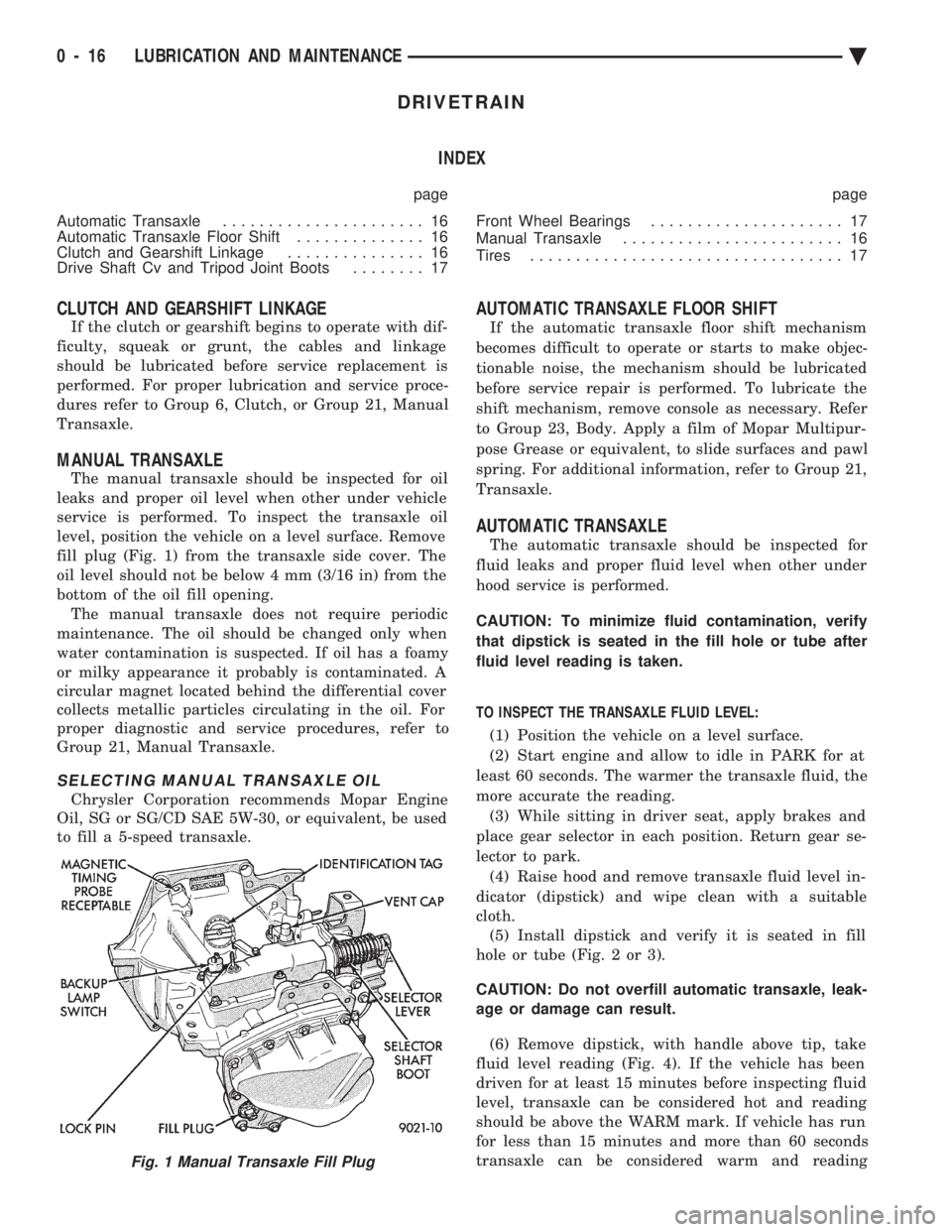
fill plug (Fig. 1) from the transaxle side cover. The
oil level should not be below 4 mm (3/16 in) from the
bottom of the oil fill opening. The manual transaxle does not require periodic
maintenance. The oil should be changed only when
water contamination is suspected. If oil has a foamy
or milky appearance it probably is contaminated. A
circular magnet located behind the differential cover
collects metallic particles circulating in the oil. For
proper diagnostic and service procedures, refer to
Group 21, Manual Transaxle.
SELECTING MANUAL TRANSAXLE OIL
Chrysler Corporation recommends Mopar Engine
Oil, SG or SG/CD SAE 5W-30, or equivalent, be used
to fill a 5-speed transaxle.
AUTOMATIC TRANSAXLE FLOOR SHIFT
If the automatic transaxle floor shift mechanism
becomes difficult to operate or starts to make objec-
tionable noise, the mechanism should be lubricated
before service repair is performed. To lubricate the
shift mechanism, remove console as necessary. Refer
to Group 23, Body. Apply a film of Mopar Multipur-
pose Grease or equivalent, to slide surfaces and pawl
spring. For additional information, refer to Group 21,
Transaxle.
AUTOMATIC TRANSAXLE
The automatic transaxle should be inspected for
fluid leaks and proper fluid level when other under
hood service is performed.
CAUTION: To minimize fluid contamination, verify
that dipstick is seated in the fill hole or tube after
fluid level reading is taken.
TO INSPECT THE TRANSAXLE FLUID LEVEL: (1) Position the vehicle on a level surface.
(2) Start engine and allow to idle in PARK for at
least 60 seconds. The warmer the transaxle fluid, the
more accurate the reading. (3) While sitting in driver seat, apply brakes and
place gear selector in each position. Return gear se-
lector to park. (4) Raise hood and remove transaxle fluid level in-
dicator (dipstick) and wipe clean with a suitable
cloth. (5) Install dipstick and verify it is seated in fill
hole or tube (Fig. 2 or 3).
CAUTION: Do not overfill automatic transaxle, leak-
age or damage can result.
(6) Remove dipstick, with handle above tip, take
fluid level reading (Fig. 4). If the vehicle has been
driven for at least 15 minutes before inspecting fluid
level, transaxle can be considered hot and reading
should be above the WARM mark. If vehicle has run
for less than 15 minutes and more than 60 seconds
transaxle can be considered warm and reading
Fig. 1 Manual Transaxle Fill Plug
0 - 16 LUBRICATION AND MAINTENANCE Ä
Page 246 of 2438
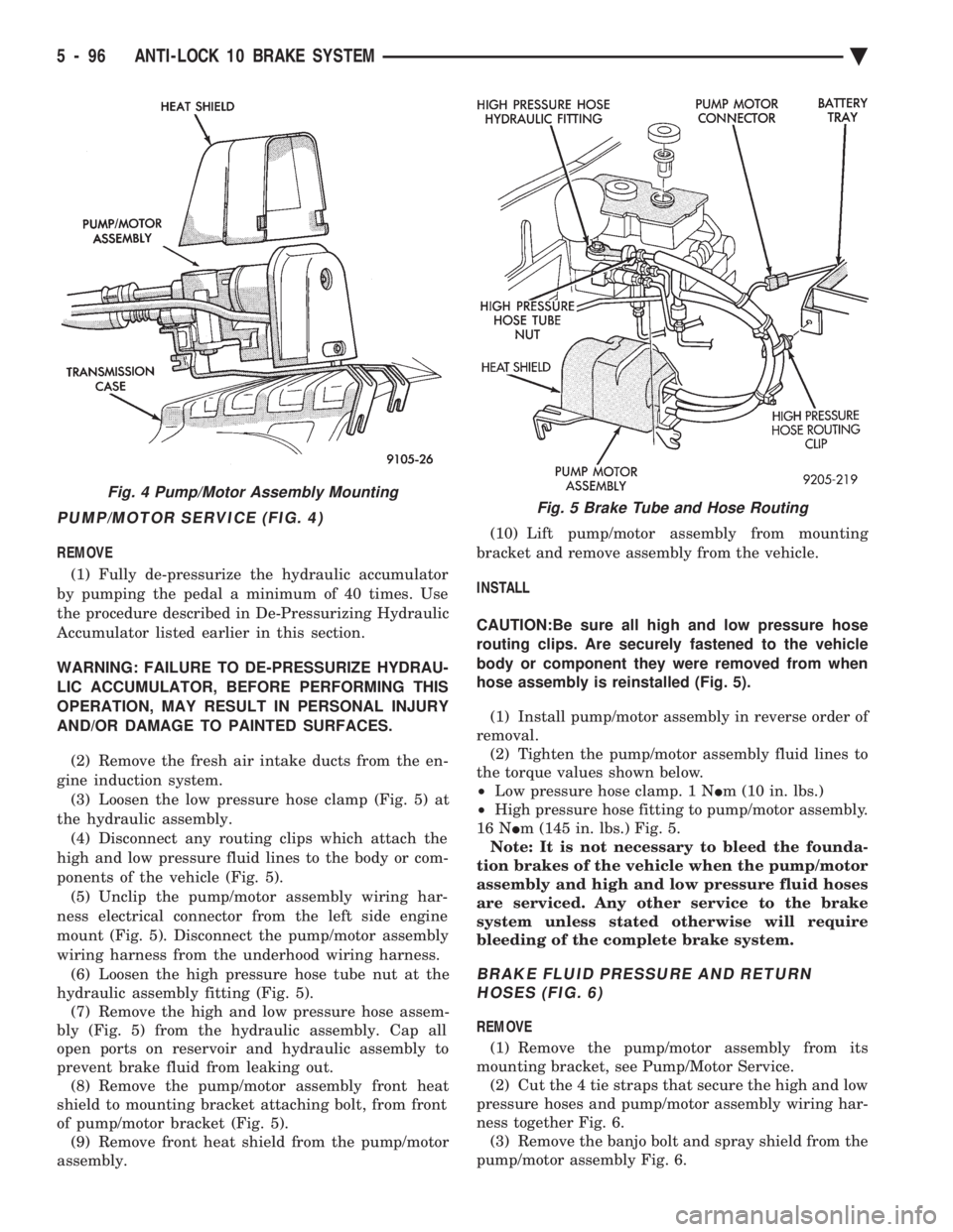
PUMP/MOTOR SERVICE (FIG. 4)
REMOVE (1) Fully de-pressurize the hydraulic accumulator
by pumping the pedal a minimum of 40 times. Use
the procedure described in De-Pressurizing Hydraulic
Accumulator listed earlier in this section.
WARNING: FAILURE TO DE-PRESSURIZE HYDRAU-
LIC ACCUMULATOR, BEFORE PERFORMING THIS
OPERATION, MAY RESULT IN PERSONAL INJURY
AND/OR DAMAGE TO PAINTED SURFACES.
(2) Remove the fresh air intake ducts from the en-
gine induction system. (3) Loosen the low pressure hose clamp (Fig. 5) at
the hydraulic assembly. (4) Disconnect any routing clips which attach the
high and low pressure fluid lines to the body or com-
ponents of the vehicle (Fig. 5). (5) Unclip the pump/motor assembly wiring har-
ness electrical connector from the left side engine
mount (Fig. 5). Disconnect the pump/motor assembly
wiring harness from the underhood wiring harness. (6) Loosen the high pressure hose tube nut at the
hydraulic assembly fitting (Fig. 5). (7) Remove the high and low pressure hose assem-
bly (Fig. 5) from the hydraulic assembly. Cap all
open ports on reservoir and hydraulic assembly to
prevent brake fluid from leaking out. (8) Remove the pump/motor assembly front heat
shield to mounting bracket attaching bolt, from front
of pump/motor bracket (Fig. 5). (9) Remove front heat shield from the pump/motor
assembly. (10) Lift pump/motor assembly from mounting
bracket and remove assembly from the vehicle.
INSTALL
CAUTION:Be sure all high and low pressure hose
routing clips. Are securely fastened to the vehicle
body or component they were removed from when
hose assembly is reinstalled (Fig. 5).
(1) Install pump/motor assembly in reverse order of
removal. (2) Tighten the pump/motor assembly fluid lines to
the torque values shown below.
² Low pressure hose clamp. 1 N Im (10 in. lbs.)
² High pressure hose fitting to pump/motor assembly.
16 N Im (145 in. lbs.) Fig. 5.
Note: It is not necessary to bleed the founda-
tion brakes of the vehicle when the pump/motor
assembly and high and low pressure fluid hoses
are serviced. Any other service to the brake
system unless stated otherwise will require
bleeding of the complete brake system.
BRAKE FLUID PRESSURE AND RETURN HOSES (FIG. 6)
REMOVE
(1) Remove the pump/motor assembly from its
mounting bracket, see Pump/Motor Service. (2) Cut the 4 tie straps that secure the high and low
pressure hoses and pump/motor assembly wiring har-
ness together Fig. 6. (3) Remove the banjo bolt and spray shield from the
pump/motor assembly Fig. 6.
Fig. 4 Pump/Motor Assembly MountingFig. 5 Brake Tube and Hose Routing
5 - 96 ANTI-LOCK 10 BRAKE SYSTEM Ä
Page 375 of 2438
BATTERY TEST PROCEDURES ON-VEHICLE INDEX
page page
Battery Charging .......................... 7
Battery Load Test ......................... 6
Battery Open Circuit Voltage Test ............. 4
Causes of Battery Discharging ............... 4 General Information
........................ 3
State of Charge Tests ...................... 4
Test Indicator ............................ 3
GENERAL INFORMATION
The battery stores, stabilizes, and produces electri-
cal current to operate various electrical systems in
the vehicle. The determination of whether a battery
is good or bad is made by the battery's ability to ac-
cept a charge. It also must produce high amperage
current output over an extended period to be able to
start the vehicle. The capability of the battery to
store electrical current comes from a chemical reac-
tion. This reaction takes place between the sulfuric
acid solution electrolyte and the lead +/- plates in
each cell of the battery. As the battery discharges,
the plates react with the acid from the electrolyte.
When the charging system charges the battery, the
water is converted to sulfuric acid in the battery. The
amount of acid, specific gravity in the electrolyte can
be measured with a hydrometer. The factory in-
stalled battery is equipped with a built in hydrome-
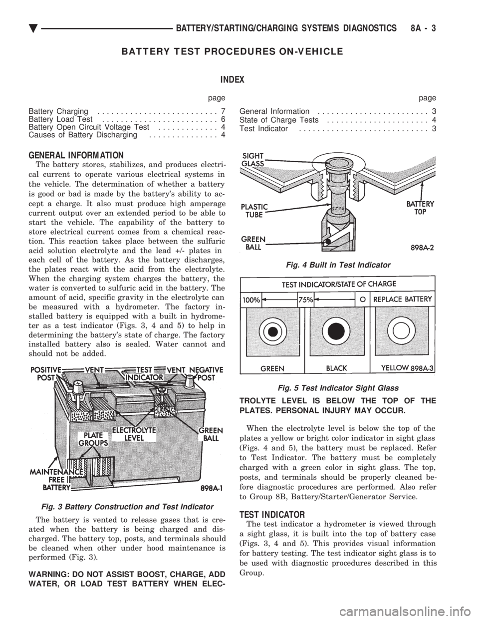
ter as a test indicator (Figs. 3, 4 and 5) to help in
determining the battery's state of charge. The factory
installed battery also is sealed. Water cannot and
should not be added.
The battery is vented to release gases that is cre-
ated when the battery is being charged and dis-
charged. The battery top, posts, and terminals should
be cleaned when other under hood maintenance is
performed (Fig. 3).
WARNING: DO NOT ASSIST BOOST, CHARGE, ADD
WATER, OR LOAD TEST BATTERY WHEN ELEC- TROLYTE LEVEL IS BELOW THE TOP OF THE
PLATES. PERSONAL INJURY MAY OCCUR.
When the electrolyte level is below the top of the
plates a yellow or bright color indicator in sight glass
(Figs. 4 and 5), the battery must be replaced. Refer
to Test Indicator. The battery must be completely
charged with a green color in sight glass. The top,
posts, and terminals should be properly cleaned be-
fore diagnostic procedures are performed. Also refer
to Group 8B, Battery/Starter/Generator Service.
TEST INDICATOR
The test indicator a hydrometer is viewed through
a sight glass, it is built into the top of battery case
(Figs. 3, 4 and 5). This provides visual information
for battery testing. The test indicator sight glass is to
be used with diagnostic procedures described in this
Group.
Fig. 3 Battery Construction and Test Indicator
Fig. 4 Built in Test Indicator
Fig. 5 Test Indicator Sight Glass
Ä BATTERY/STARTING/CHARGING SYSTEMS DIAGNOSTICS 8A - 3
Page 381 of 2438

IGNITION OFF DRAW (IOD)
GENERAL INFORMATION
A normal electrical system will draw from 5 to 30
milliamperes from the battery. This is with the ignition
in the OFF position, and all non-ignition controlled cir-
cuits in proper working order. The amount of IOD will
depend on body model and electrical components. A ve-
hicle that has not been operated for an extended period
of approximately 20 days may discharge the battery to
an inadequate level. In this case, the Main Fusible Link
Connector should be disconnected. The Main Fusible
Link connector is located rearward of the battery on the
engine wiring harness (Fig. 19).
If the IOD is over 30 milliamperes, the defect must
be found and corrected before condemning the bat-
tery. Usually, the battery can be charged and re-
turned to service (Fig. 16).
IGNITION OFF DRAW (IOD) TESTS
VEHICLES WITHOUT ELECTRONIC AUTOMATIC TRANSMISSION/LOAD LEVELINGSUSPENSION OR ALARM SYSTEMS
Testing for HIGHER AMPERAGE IOD must be
performed first to prevent damage to most milliamp
meters. A standard 12 volt test light and a milliamp meter
that is equipped with two leads will be used for the
following tests. The milliamp meter should be able to
handle up to two amps.
(1) Verify that all electrical accessories are OFF.
Turn off all lights, close trunk lid, close glove box door,
turn off sun visor vanity lights, close all doors and re- move ignition key. Allow the Illuminated Entry System
if equipped to time out in approximately 30 seconds.
(2) Verify the engine compartment lamp bulb is
working by opening/closing hood. Remove the lamp. (3) Disconnect negative battery cable (Fig. 15).
(4) Connect a typical 12 volt test light between the
negative cable clamp and the negative battery post (Fig.
19). The test light may be brightly lit for up to three
minutes or may not be lit at all. This depending on the
body model or electronic components on the vehicle. (a) The term brightly used throughout the follow-
ing tests. This implies the brightness of the test light
will be the same as if it were connected across the
battery posts. This would be with a fully charged bat-
tery.
(b) The test light or the milliamp meter MUST
be positively connected to the battery post and the
battery cable during all IOD testing. (c) Do not allow the test light or the milliamp
meter to become disconnected during any of the
IOD tests. If this happens, the electronic timer
functions will be started and all IOD tests must be
repeated from the beginning. Clamp the test light
at both ends to prevent accidental disconnection.
(d) After three minutes time has elapsed, the test
light should turn OFF or be dimly lit depending on
the electronic components on the vehicle. If the test
light remains BRIGHTLY lit, do not disconnect test
light. Disconnect each fuse or circuit breaker until
test light is either OFF or DIMLY lit. Refer to the
Front Wheel Drive Car Wiring Diagrams Service
Manual. This will eliminate higher amperage IOD. It
is now safe to install the milliamp meter without
damage to the meter to check for low amperage IOD.
(e) Possible sources of high IOD are usually ve-
hicle lamps trunk lamp, glove compartment, lug-
gage compartment, etc.. (f) If test light is still brightly lit after discon-
necting each fuse and circuit breaker, disconnect
the wiring harness from the generator. Refer to
Generator Testing. Do not disconnect test light.
CAUTION: This last test has higher amperage IOD and
must be performed before going on with low amper-
age IOD tests. The higher amperage IOD must be elim-
inated before hooking up milliamp meter to check for
low amperage IOD. If higher amperage IOD has not
been eliminated, milliamp meter may be damaged.
Most milliamp meters will not handle over one or two
amps. Do not hook up meter if test light is glowing
brightly. Refer to maximum amperage specifications
and instructions supplied with milliamp meter.
After higher amperage IOD has been corrected, low
amperage IOD may be checked. The MAXIMUM IOD=
30 MILLIAMPERES.
Fig. 19 IOD Test
Ä BATTERY/STARTING/CHARGING SYSTEMS DIAGNOSTICS 8A - 9
Page 513 of 2438
(3) Remove four screws from ash receiver/cup
holder housing. (4) For installation reverse above procedures.
AIR CONDITIONING CONTROLREPLACEMENT
(1) Disconnect battery negative cable and isolate
or remove fuse #2 prior to removing switch or wires
may short to ground. (2) Remove center bezel. Disconnect ash receiver
lamp socket. (3) Remove glove box assembly. Refer to Glove Box
Assembly Replacement. (4) Reach through glove box opening and discon-
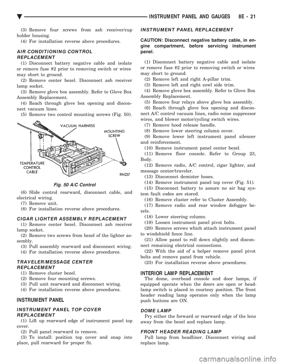
nect vacuum lines. (5) Remove two control mounting screws (Fig. 50).
(6) Slide control rearward, disconnect cable, and
electrical wiring. (7) Remove unit.
(8) For installation reverse above procedures.
CIGAR LIGHTER ASSEMBLY REPLACEMENT
(1) Remove center bezel. Disconnect ash receiver
lamp socket. (2) Remove two screws from bezel of the lighter as-
sembly. (3) Pull assembly rearward and disconnect wiring.
(4) For installation reverse above procedures.
TRAVELER/MESSAGE CENTER REPLACEMENT
(1) Remove cluster bezel.
(2) Remove four mounting screws.
(3) Pull unit rearward and disconnect wiring.
(4) For installation reverse above procedures.
INSTRUMENT PANEL
INSTRUMENT PANEL TOP COVER REPLACEMENT
(1) Lift up rearward edge of instrument panel top
cover. (2) Pull panel rearward to remove.
(3) To install: position top cover and snap into
place, pull rearward for proper fit.
INSTRUMENT PANEL REPLACEMENT
CAUTION: Disconnect negative battery cable, in en-
gine compartment, before servicing instrument
panel.
(1) Disconnect battery negative cable and isolate
or remove fuse #2 prior to removing switch or wires
may short to ground. (2) Remove left and right A-pillar trim.
(3) Remove left and right cowl side trim.
(4) Remove glove box assembly. Refer to Glove Box
Assembly Replacement. (5) Remove four relays above glove box assembly.
(6) Reach through glove box opening and discon-
nect A/C control vacuum lines, radio noise suppressor
wires, and blower motor/cycling switch wires. (7) Remove hood release handle.
(8) Remove lower steering column cover.
(9) Remove lower left instrument panel silencer
and reinforcement. (10) Remove instrument panel center bezel.
(11) Remove floor console. Refer to Group 23,
Body. (12) Remove radio, A/C control, cigar lighter, and
message center/traveler. (13) Disconnect demister hoses.
(14) Remove instrument panel top cover (Fig. 51).
(15) Disconnect battery to assure no air bag sys-
tem fault codes are stored. (16) Remove cluster refer to Cluster Assembly.
(17) Remove radio and rear window defogger be-
zels. (18) Lower steering column.
(19) Loosen instrument panel pivot bolts.
(20) Remove screws which attach instrument panel
to windshield fence line. (21) Allow panel to roll down slightly and discon-
nect remaining electrical connections. (22) With the aid of a helper remove panel pivot
bolts and remove panel from vehicle. (23) For installation reverse above procedures.
INTERIOR LAMP REPLACEMENT
The dome, overhead console and door lamps, if
equipped operate when the doors are open or head-
lamp switch is placed in courtesy position. The front
header reading lamp operates only when the lamp
push buttons are ON.
DOME LAMP
Pry either the forward or rearward edge of the lens
away from the bezel and replace lamp.
FRONT HEADER READING LAMP
Pull lamp from headliner. Disconnect wiring and
replace lamp.
Fig. 50 A/C Control
Ä INSTRUMENT PANEL AND GAUGES 8E - 21
Page 533 of 2438
(4) Remove panel top cover by pushing forward
and prying up, using a straight edge to assist in the
removal. (5) Disconnect bulkhead connector at brace under
instrument panel at left side. (6) Remove glovebox/ash receiver module and right
instrument panel silencer. (7) Remove center panel support brace and air bag
diagnostic module assembly. (8) Disconnect wiring to airbag module.
(9) Remove upper and lower cluster bezels.
(10) Remove steering column cover.
(11) Remove steering column mounting nuts and
lower steering column. (12) Unhook shift indicator cable eyelet from steer-
ing column actuator. (13) Unlatch lock tab in shift indicator column in-
sert and squeeze legs together to remove from steer-
ing column. (14) Remove cluster assembly while guiding trans-
mission range indicator guide tube through access
hole in the base panel. (15) Remove instrument panel steering column
opening support/hood release handle assembly. (16) Remove two steering column upper studs and
loosen side cowl tie-down bolts. (17) Remove steering column tilt lever.
(18) Remove upper and lower lock housing shroud.
(19) Remove lower fixed shroud.
(20) Remove upper fixed shroud (snaps in place).
(21) Disconnect airbag pigtail, ignition switch and
halo light/key buzzer switch wiring. (22) Disconnect Multi-function switch by loosening
connector jack screw and pulling connector from
switch. (23) Disconnect airbag pigtail from wiring trough
housing by pulling two push fasteners. (24) Remove wiring trough from steering column.
(25) Remove defroster ducts.
(26) Remove five screws along fence line and roll
panel down, attach a hook to hold in position. (27) Open hood and remove plenum grill.
(28) Disconnect washer bottle, resistor block and
under hood lamp wiring. Washer bottle must be re-
moved to gain access. (29) Remove grommet and pull plenum wiring into
vehicle through plenum panel. (30) Disconnect right demister hose from instru-
ment panel. (31) Disconnect antenna cable.
(32) Disconnect right and left 25 way body wiring
connectors. (33) Disconnect A/C heater control cables, wiring
connectors and vacuum harness. (34) Remove right side panel ground wire.
(35) Disconnect body controller wiring.
(36) Remove instrument panel assembly from vehi-
cle. (37) For installation reverse above procedures.
INTERIOR LAMP REPLACEMENT
The reading, overhead console and door lamps op-
erate when the doors are open or headlamp switch is
placed in courtesy position. Front overhead lamps re-
fer to Group 8C, Overhead Console.
TRUNK LAMP
The lamp has easily accessible without removing
components.
DOOR LAMP
Pry along the forward edge of the lens and pivot
lens out of the door trim panel. Remove lamp. To re-
move lamp housing, remove door trim panel. Refer to
Group 23, Body. Disconnect all wiring. Remove
screws, if so equipped securing lamp housing to trim
panel, and replace housing.
CÐPILLAR READING/COURTESY LAMP
Pry along the rearward edge of the lamp and pivot
lamp out from quarter trim panel. Disconnect wiring
and remove lamp cover. Replace lamp. The lamp operates when the doors are open or the
headlamp switch is turned to the courtesy mode. The
lamp will function as a reading lamp when the doors
are closed and the button switch on the lamp is de-
pressed.
ROOF RAIL READING
Pry along the bottom edge of the lens and pivot
lens out. Replace lamp. To remove the lamp, remove
the screw which retains the coat hook. Remove the
garnish molding. Disconnect the wiring harness. Re-
move the two clips which retain the lamp to the
molding. Replace lamp. The lamp operates like the
C-pillar reading/courtesy lamp.
Ä INSTRUMENT PANEL AND GAUGES 8E - 41
Page 546 of 2438
INSTALLATION (1) Latch switch linkage in the up position.
(2) Insert dimmer shaft into dimmer knob while
aligning switch in to switch pod assembly. (3) Install switch attaching screws.
(4) Unlatch linkage and install onto push buttons.
(5) Operate all switch modes for correct operation.
(6) Install turn signal switch.
(7) Reconnect wiring for turn signal switch, mak-
ing sure wire is properly clipped into position. (8) Place together the inner and outer bezels. In-
stall five inner switch pod panel screws and three
screws from underneath the switch pod. (9) Install turn signal lever by pushing straight
into switch assembly. (10) Install switch pod assembly.
LOWER STEERING COLUMN COVER REMOVAL
(1) Remove screws along top edge of cover.
(2) Remove screw at each lower corner of cover. (3) Remove cover from underneath over column
cover. (4) For installation reverse above procedures.
GLOVEBOX MODULE REMOVAL
(1) Disconnect battery negative cable and isolate
or remove fuse #26 prior to removing switch or wires
may short to ground. (2) Remove cowl side trim panel.
(3) Remove screws at right end of glovebox and
lower corners. (4) Open glovebox, remove light and disconnect
wiring. (5) Remove five screws along top of glovebox frame
and screw at each lower corner. (6) Remove glovebox assembly.
(7) For installation reverse above procedures.
CONCEALED HEADLAMP MODULE REMOVAL
(1) Remove left under panel silencer.
(2) Slide module off bayonet bracket while disen-
gaging spring retainer. (3) Disconnect wiring terminal.
(4) For installation reverse above procedures.
HOOD RELEASE REMOVE
(1) Remove lower column cover.
(2) Remove screws on fuse block and move aside.
(3) Remove screws on hood release assembly to re-
move. (4) For installation reverse above procedures.
AIR CONDITIONING CONTROL REMOVE
(1) Remove center stack bezel.
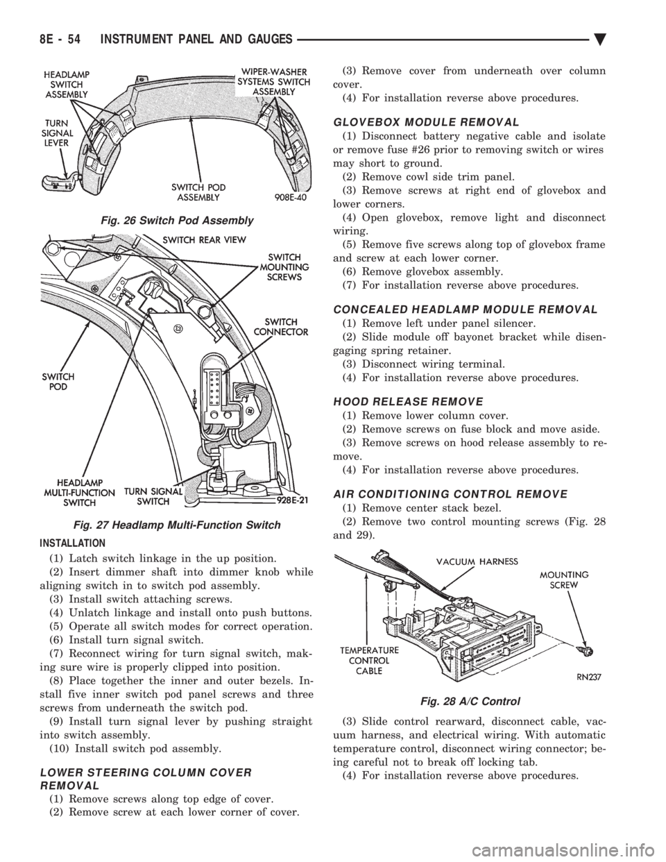
(2) Remove two control mounting screws (Fig. 28
and 29).
(3) Slide control rearward, disconnect cable, vac-
uum harness, and electrical wiring. With automatic
temperature control, disconnect wiring connector; be-
ing careful not to break off locking tab. (4) For installation reverse above procedures.
Fig. 26 Switch Pod Assembly
Fig. 27 Headlamp Multi-Function Switch
Fig. 28 A/C Control
8E - 54 INSTRUMENT PANEL AND GAUGES Ä