1993 CHEVROLET DYNASTY open hood
[x] Cancel search: open hoodPage 1793 of 2438
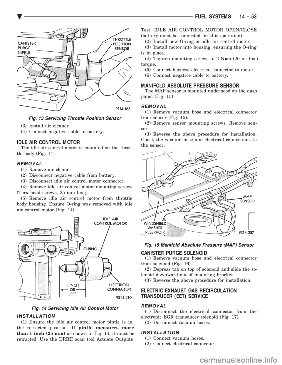
(3) Install air cleaner.
(4) Connect negative cable to battery.
IDLE AIR CONTROL MOTOR
The idle air control motor is mounted on the throt-
tle body (Fig. 14).
REMOVAL
(1) Remove air cleaner.
(2) Disconnect negative cable from battery.
(3) Disconnect idle air control motor connector.
(4) Remove idle air control motor mounting screws
(Torx head screws, 25 mm long). (5) Remove idle air control motor from throttle
body housing. Ensure O-ring was removed with idle
air control motor (Fig. 14).
INSTALLATION
(1) Ensure the idle air control motor pintle is in
the retracted position. If pintle measures more
than 1 inch (25 mm) as shown in Fig. 14, it must be
retracted. Use the DRBII scan tool Actuate Outputs Test, IDLE AIR CONTROL MOTOR OPEN/CLOSE
(battery must be connected for this operation). (2) Install new O-ring on idle air control motor.
(3) Install motor into housing, ensuring the O-ring
is in place. (4) Tighten mounting screws to 2 N Im (20 in. lbs.)
torque. (5) Connect harness electrical connector to motor.
(6) Connect negative cable to battery.
MANIFOLD ABSOLUTE PRESSURE SENSOR
The MAP sensor is mounted underhood on the dash
panel (Fig. 15)
REMOVAL
(1) Remove vacuum hose and electrical connector
from sensor (Fig. 15). (2) Remove sensor mounting screws. Remove sen-
sor. (3) Reverse the above procedure for installation.
Check the vacuum hose and electrical connections to
the sensor.
CANISTER PURGE SOLENOID
(1) Remove vacuum hose and electrical connector
from solenoid (Fig. 16). (2) Depress tab on top of solenoid and slide the so-
lenoid downward out of mounting bracket. (3) Reverse the above procedure for installation.
ELECTRIC EXHAUST GAS RECIRCULATION
TRANSDUCER (EET) SERVICE
REMOVAL
(1) Disconnect the electrical connector from the
electronic EGR transducer solenoid (Fig. 17). (2) Disconnect vacuum hoses.
INSTALLATION
(1) Connect vacuum hoses.
(2) Connect electrical connector.
Fig. 15 Manifold Absolute Pressure (MAP) Sensor
Fig. 13 Servicing Throttle Position Sensor
Fig. 14 Servicing Idle Air Control Motor
Ä FUEL SYSTEMS 14 - 53
Page 1828 of 2438
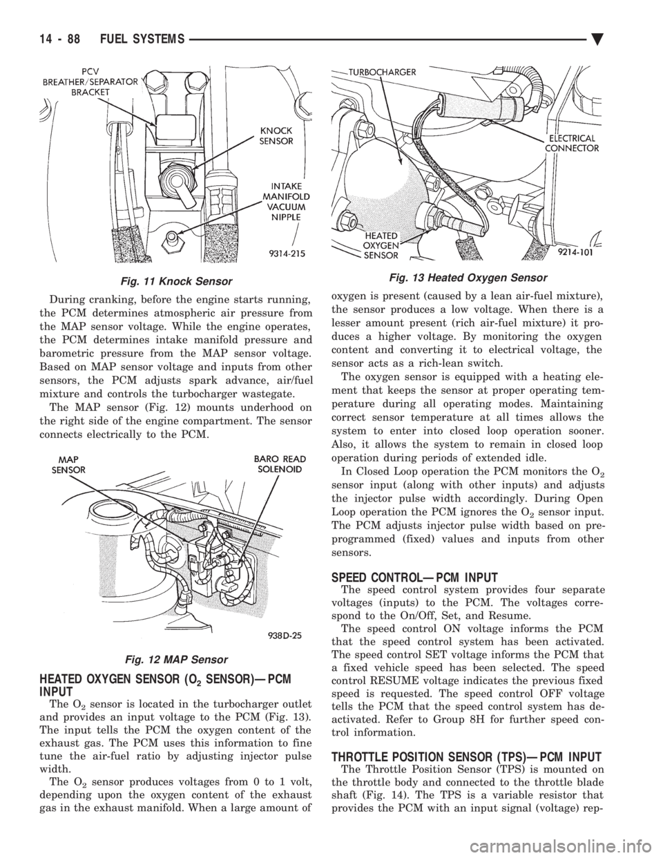
During cranking, before the engine starts running,
the PCM determines atmospheric air pressure from
the MAP sensor voltage. While the engine operates,
the PCM determines intake manifold pressure and
barometric pressure from the MAP sensor voltage.
Based on MAP sensor voltage and inputs from other
sensors, the PCM adjusts spark advance, air/fuel
mixture and controls the turbocharger wastegate. The MAP sensor (Fig. 12) mounts underhood on
the right side of the engine compartment. The sensor
connects electrically to the PCM.
HEATED OXYGEN SENSOR (O2SENSOR)ÐPCM
INPUT
The O2sensor is located in the turbocharger outlet
and provides an input voltage to the PCM (Fig. 13).
The input tells the PCM the oxygen content of the
exhaust gas. The PCM uses this information to fine
tune the air-fuel ratio by adjusting injector pulse
width. The O
2sensor produces voltages from 0 to 1 volt,
depending upon the oxygen content of the exhaust
gas in the exhaust manifold. When a large amount of oxygen is present (caused by a lean air-fuel mixture),
the sensor produces a low voltage. When there is a
lesser amount present (rich air-fuel mixture) it pro-
duces a higher voltage. By monitoring the oxygen
content and converting it to electrical voltage, the
sensor acts as a rich-lean switch. The oxygen sensor is equipped with a heating ele-
ment that keeps the sensor at proper operating tem-
perature during all operating modes. Maintaining
correct sensor temperature at all times allows the
system to enter into closed loop operation sooner.
Also, it allows the system to remain in closed loop
operation during periods of extended idle. In Closed Loop operation the PCM monitors the O
2
sensor input (along with other inputs) and adjusts
the injector pulse width accordingly. During Open
Loop operation the PCM ignores the O
2sensor input.
The PCM adjusts injector pulse width based on pre-
programmed (fixed) values and inputs from other
sensors.
SPEED CONTROLÐPCM INPUT
The speed control system provides four separate
voltages (inputs) to the PCM. The voltages corre-
spond to the On/Off, Set, and Resume. The speed control ON voltage informs the PCM
that the speed control system has been activated.
The speed control SET voltage informs the PCM that
a fixed vehicle speed has been selected. The speed
control RESUME voltage indicates the previous fixed
speed is requested. The speed control OFF voltage
tells the PCM that the speed control system has de-
activated. Refer to Group 8H for further speed con-
trol information.
THROTTLE POSITION SENSOR (TPS)ÐPCM INPUT
The Throttle Position Sensor (TPS) is mounted on
the throttle body and connected to the throttle blade
shaft (Fig. 14). The TPS is a variable resistor that
provides the PCM with an input signal (voltage) rep-
Fig. 11 Knock Sensor
Fig. 12 MAP Sensor
Fig. 13 Heated Oxygen Sensor
14 - 88 FUEL SYSTEMS Ä
Page 2167 of 2438
AA-VEHICLE BODY COMPONENT SERVICE INDEX
page page
A-Pillar and Roof Rail Mouldings ............. 25
B-Pillar Trim Panel ....................... 25
Body Side Moulding and Applique ............ 24
Cowl Cover ............................. 13
Cowl Panel Trim and Scuff Plates ............ 25
Door Opening Weatherstrips ................ 24
Floor Carpet ............................ 30
Front Center Console ..................... 29
Front Door and Hinge ..................... 15
Front Door Belt Moulding and Weatherstrip ..... 17
Front Door Glass ........................ 17
Front Door Glass Channel and Run Weatherstrip . 18
Front Door Glass Run Lower Channel ......... 18
Front Door Latch ......................... 16
Front Door Side View Mirror ................ 17
Front Door Silencer and Water Shield ......... 15
Front Door Trim Panel .................... 14
Front Door Window Regulator/Manual ......... 18
Front Door Window Regulator/Power .......... 19
Front End Splash Shields .................. 13
Front Fender ............................ 14
Front Power Door Lock Actuator ............. 19
Front Seat Belts ......................... 27
Front Seats ............................. 28
Fuel Fill Door ........................... 36
Grille .................................. 11
Head Lining ............................. 30
Hood and Hinges ........................ 11
Hood Latch and Release Cable .............. 12
Outside Front Door Latch Release Handle ..... 16
Outside Rear Door Latch Release Handle ...... 21 Overhead Console
........................ 30
Quarter Extension Trim Panel ............... 27
Quarter Trim Panel ....................... 27
Rear Deck Filler Panel .................... 31
Rear Door and Hinge ..................... 20
Rear Door Belt Moulding and Weatherstrip ..... 22
Rear Door Glass ......................... 22
Rear Door Glass Run Weatherstrip ........... 22
Rear Door Glass Stationary Glass Module ..... 23
Rear Door Latch ......................... 21
Rear Door Silencer and Water Shield ......... 20
Rear Door Trim Panel ..................... 20
Rear Door Window Regulator/Manual ......... 23
Rear Door Window Regulator/Power .......... 23
Rear Power Door Lock Actuator ............. 22
Rear Seat Belts .......................... 28
Rear Seats ............................. 28
Rear Shelf Trim Panel ..................... 27
Rear Window Glass ...................... 32
Sun Roof Air Deflector .................... 31
Sun Roof Drain Tubes .................... 31
Sun Roof Weatherstrip .................... 31
Trunk Lid .............................. 33
Trunk Lid Hinge ......................... 34
Trunk Lid Latch .......................... 34
Trunk Lid Lock .......................... 34
Trunk Lid Luggage Rack ................... 35
Trunk Lid Torsion Bar ..................... 34
Trunk Lining ............................ 35
Trunk Opening Weatherstrip ................ 35
Vinyl Roof Bonnet ........................ 31
GRILLE
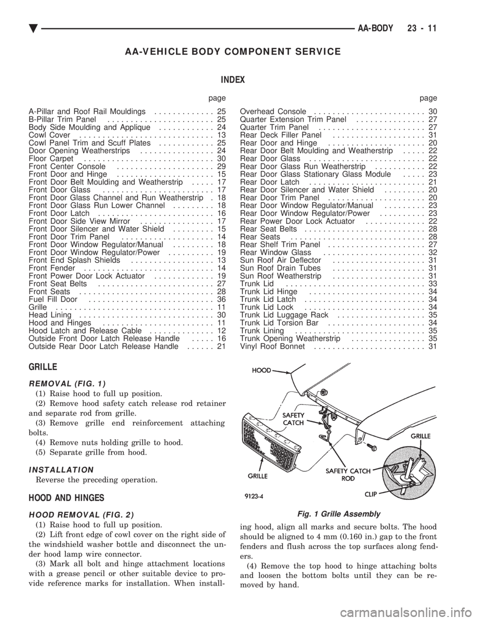
REMOVAL (FIG. 1)
(1) Raise hood to full up position.
(2) Remove hood safety catch release rod retainer
and separate rod from grille. (3) Remove grille end reinforcement attaching
bolts. (4) Remove nuts holding grille to hood.
(5) Separate grille from hood.
INSTALLATION
Reverse the preceding operation.
HOOD AND HINGES
HOOD REMOVAL (FIG. 2)
(1) Raise hood to full up position.
(2) Lift front edge of cowl cover on the right side of
the windshield washer bottle and disconnect the un-
der hood lamp wire connector. (3) Mark all bolt and hinge attachment locations
with a grease pencil or other suitable device to pro-
vide reference marks for installation. When install- ing hood, align all marks and secure bolts. The hood
should be aligned to 4 mm (0.160 in.) gap to the front
fenders and flush across the top surfaces along fend-
ers. (4) Remove the top hood to hinge attaching bolts
and loosen the bottom bolts until they can be re-
moved by hand.
Fig. 1 Grille Assembly
Ä AA-BODY 23 - 11
Page 2169 of 2438
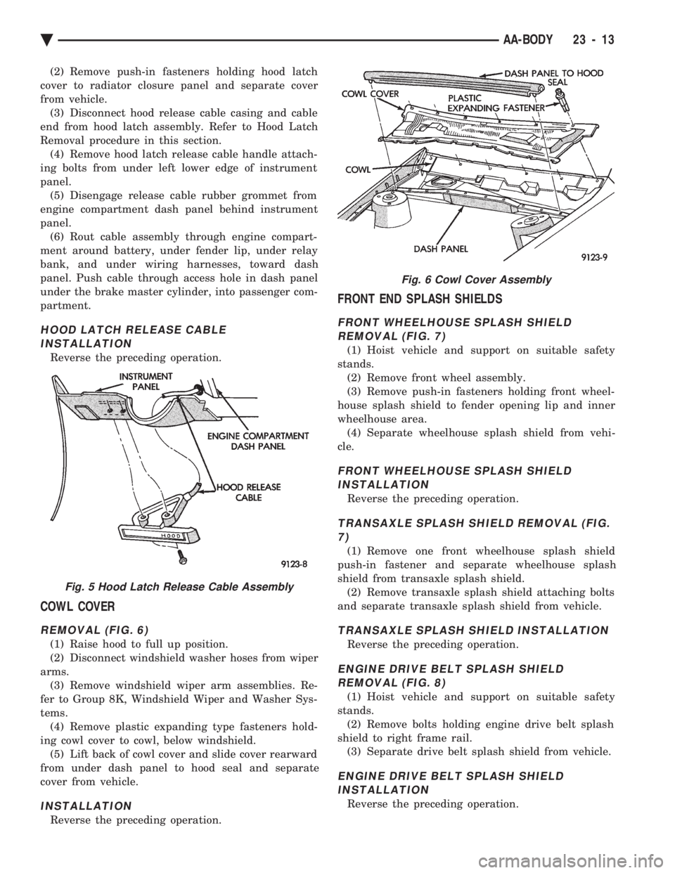
(2) Remove push-in fasteners holding hood latch
cover to radiator closure panel and separate cover
from vehicle. (3) Disconnect hood release cable casing and cable
end from hood latch assembly. Refer to Hood Latch
Removal procedure in this section. (4) Remove hood latch release cable handle attach-
ing bolts from under left lower edge of instrument
panel. (5) Disengage release cable rubber grommet from
engine compartment dash panel behind instrument
panel. (6) Rout cable assembly through engine compart-
ment around battery, under fender lip, under relay
bank, and under wiring harnesses, toward dash
panel. Push cable through access hole in dash panel
under the brake master cylinder, into passenger com-
partment.
HOOD LATCH RELEASE CABLE INSTALLATION
Reverse the preceding operation.
COWL COVER
REMOVAL (FIG. 6)
(1) Raise hood to full up position.
(2) Disconnect windshield washer hoses from wiper
arms. (3) Remove windshield wiper arm assemblies. Re-
fer to Group 8K, Windshield Wiper and Washer Sys-
tems. (4) Remove plastic expanding type fasteners hold-
ing cowl cover to cowl, below windshield. (5) Lift back of cowl cover and slide cover rearward
from under dash panel to hood seal and separate
cover from vehicle.
INSTALLATION
Reverse the preceding operation.
FRONT END SPLASH SHIELDS
FRONT WHEELHOUSE SPLASH SHIELD REMOVAL (FIG. 7)
(1) Hoist vehicle and support on suitable safety
stands. (2) Remove front wheel assembly.
(3) Remove push-in fasteners holding front wheel-
house splash shield to fender opening lip and inner
wheelhouse area. (4) Separate wheelhouse splash shield from vehi-
cle.
FRONT WHEELHOUSE SPLASH SHIELD INSTALLATION
Reverse the preceding operation.
TRANSAXLE SPLASH SHIELD REMOVAL (FIG.7)
(1) Remove one front wheelhouse splash shield
push-in fastener and separate wheelhouse splash
shield from transaxle splash shield. (2) Remove transaxle splash shield attaching bolts
and separate transaxle splash shield from vehicle.
TRANSAXLE SPLASH SHIELD INSTALLATION
Reverse the preceding operation.
ENGINE DRIVE BELT SPLASH SHIELD REMOVAL (FIG. 8)
(1) Hoist vehicle and support on suitable safety
stands. (2) Remove bolts holding engine drive belt splash
shield to right frame rail. (3) Separate drive belt splash shield from vehicle.
ENGINE DRIVE BELT SPLASH SHIELDINSTALLATION
Reverse the preceding operation.
Fig. 5 Hood Latch Release Cable Assembly
Fig. 6 Cowl Cover Assembly
Ä AA-BODY 23 - 13
Page 2170 of 2438
FRONT FENDER
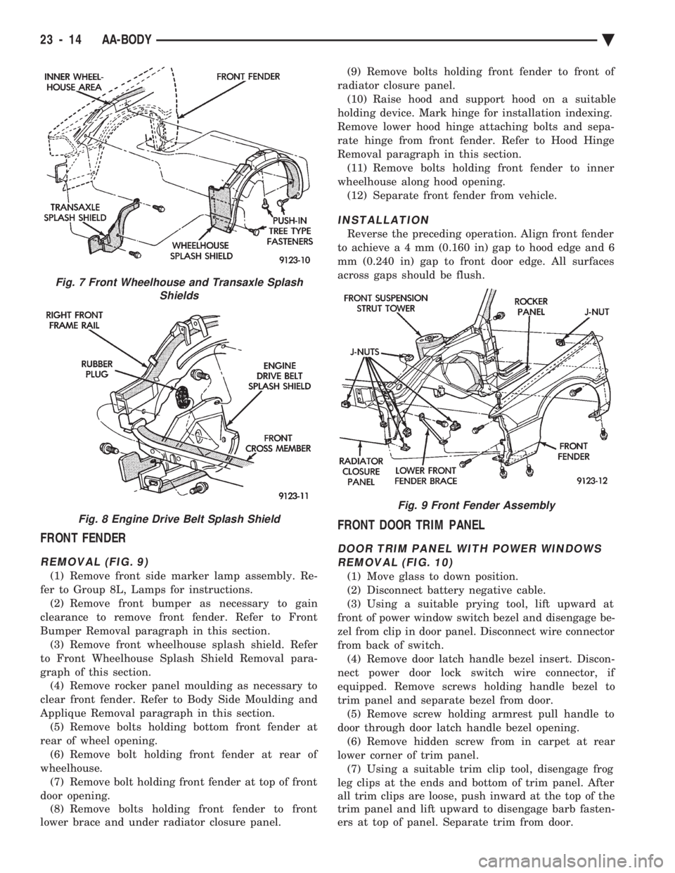
REMOVAL (FIG. 9)
(1) Remove front side marker lamp assembly. Re-
fer to Group 8L, Lamps for instructions. (2) Remove front bumper as necessary to gain
clearance to remove front fender. Refer to Front
Bumper Removal paragraph in this section. (3) Remove front wheelhouse splash shield. Refer
to Front Wheelhouse Splash Shield Removal para-
graph of this section. (4) Remove rocker panel moulding as necessary to
clear front fender. Refer to Body Side Moulding and
Applique Removal paragraph in this section. (5) Remove bolts holding bottom front fender at
rear of wheel opening. (6) Remove bolt holding front fender at rear of
wheelhouse. (7) Remove bolt holding front fender at top of front
door opening. (8) Remove bolts holding front fender to front
lower brace and under radiator closure panel. (9) Remove bolts holding front fender to front of
radiator closure panel. (10) Raise hood and support hood on a suitable
holding device. Mark hinge for installation indexing.
Remove lower hood hinge attaching bolts and sepa-
rate hinge from front fender. Refer to Hood Hinge
Removal paragraph in this section. (11) Remove bolts holding front fender to inner
wheelhouse along hood opening. (12) Separate front fender from vehicle.
INSTALLATION
Reverse the preceding operation. Align front fender
to achiev ea4mm (0.160 in) gap to hood edge and 6
mm (0.240 in) gap to front door edge. All surfaces
across gaps should be flush.
FRONT DOOR TRIM PANEL
DOOR TRIM PANEL WITH POWER WINDOWS REMOVAL (FIG. 10)
(1) Move glass to down position.
(2) Disconnect battery negative cable.
(3) Using a suitable prying tool, lift upward at
front of power window switch bezel and disengage be-
zel from clip in door panel. Disconnect wire connector
from back of switch. (4) Remove door latch handle bezel insert. Discon-
nect power door lock switch wire connector, if
equipped. Remove screws holding handle bezel to
trim panel and separate bezel from door. (5) Remove screw holding armrest pull handle to
door through door latch handle bezel opening. (6) Remove hidden screw from in carpet at rear
lower corner of trim panel. (7) Using a suitable trim clip tool, disengage frog
leg clips at the ends and bottom of trim panel. After
all trim clips are loose, push inward at the top of the
trim panel and lift upward to disengage barb fasten-
ers at top of panel. Separate trim from door.
Fig. 7 Front Wheelhouse and Transaxle Splash Shields
Fig. 8 Engine Drive Belt Splash Shield
Fig. 9 Front Fender Assembly
23 - 14 AA-BODY Ä
Page 2193 of 2438
AC-VEHICLE BODY COMPONENT SERVICE INDEX
page page
A-Pillar and Roof Rail Mouldings ............. 46
B-Pillar Trim Panel ....................... 46
Body Mouldings .......................... 49
Cowl Panel Trim and Scuff Plates ............ 46
Door Frame Trim Moulding ................. 41
Front Door and Hinge ..................... 41
Front Door Glass ........................ 43
Front Door Latch ......................... 42
Front Door Trim Panel .................... 40
Front Door Water Shield ................... 41
Front Door Window Regulator ............... 42
Front End Splash Shields .................. 40
Front Seat Belts ......................... 47
Front Seats ............................. 48
Grille AC/C Body ......................... 38
Grille AC/D or AC/C-H Body ................ 37
Grille Extension Moulding .................. 37
Grille Opening Panel AC/C-Body ............. 38
Grille Opening Panel AC/D and AC/C-H Body . . . 37
Head Lining ............................. 45
Hood and Hinges ........................ 38
Hood Latch and Release Cable .............. 39
Hood Latch Release Cable ................. 39 Hood Ornament AC/C
..................... 38
Outside Door Handle ...................... 42
Overhead Console ........................ 45
Quarter Trim Panel ....................... 46
Rear Deck Filler Panel .................... 49
Rear Door and Hinge ..................... 44
Rear Door Frame Trim Moulding ............. 43
Rear Door Glass ......................... 45
Rear Door Glass Lift Plate and Guide Bar ..... 45
Rear Door Latch ......................... 44
Rear Door Outside Handle ................. 44
Rear Door Silencer and Water Shield ......... 43
Rear Door Trim Panel ..................... 43
Rear Door Window Regulator ............... 45
Rear Seat Belts .......................... 47
Rear Seats ............................. 49
Rear Shelf Trim Panel ..................... 47
Rear Window Glass ...................... 50
Side View Mirror Trim Cover ................ 41
Trunk Lid .............................. 50
Trunk Lid Hinge ......................... 51
Trunk Lid Torsion Bar ..................... 51
Vinyl Roof Bonnet ........................ 49
GRILLE AC/D or AC/C-H BODY
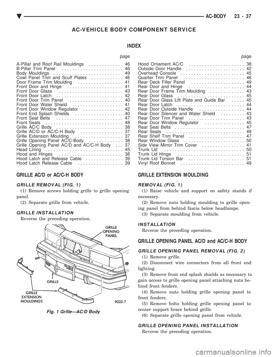
GRILLE REMOVAL (FIG. 1)
(1) Remove screws holding grille to grille opening
panel. (2) Separate grille from vehicle.
GRILLE INSTALLATION
Reverse the preceding operation.
GRILLE EXTENSION MOULDING
REMOVAL (FIG. 1)
(1) Raise vehicle and support on safety stands if
necessary. (2) Remove nuts holding moulding to grille open-
ing panel from behind fascia below headlamps. (3) Separate moulding from vehicle.
INSTALLATION
Reverse the preceding operation.
GRILLE OPENING PANEL AC/D and AC/C-H BODY
GRILLE OPENING PANEL REMOVAL (FIG. 2)
(1) Remove grille.
(2) Disconnect wire connectors from all front end
lighting. (3) Remove front end splash shields as necessary to
gain access to grille opening panel attaching nuts be-
hind front fenders. (4) Remove nuts holding grille opening panel to
front fenders. (5) Remove bolts holding grille opening panel to
center support brace behind grille. (6) Separate grille opening panel from vehicle.
GRILLE OPENING PANEL INSTALLATION
Reverse the preceding operation.
Fig. 1 GrilleÐAC/D Body
Ä AC-BODY 23 - 37
Page 2194 of 2438
GRILLE AC/C BODY
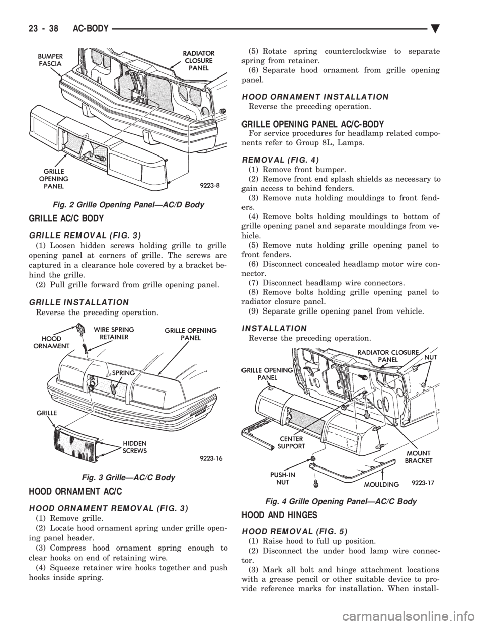
GRILLE REMOVAL (FIG. 3)
(1) Loosen hidden screws holding grille to grille
opening panel at corners of grille. The screws are
captured in a clearance hole covered by a bracket be-
hind the grille. (2) Pull grille forward from grille opening panel.
GRILLE INSTALLATION
Reverse the preceding operation.
HOOD ORNAMENT AC/C
HOOD ORNAMENT REMOVAL (FIG. 3)
(1) Remove grille.
(2) Locate hood ornament spring under grille open-
ing panel header. (3) Compress hood ornament spring enough to
clear hooks on end of retaining wire. (4) Squeeze retainer wire hooks together and push
hooks inside spring. (5) Rotate spring counterclockwise to separate
spring from retainer. (6) Separate hood ornament from grille opening
panel.
HOOD ORNAMENT INSTALLATION
Reverse the preceding operation.
GRILLE OPENING PANEL AC/C-BODY
For service procedures for headlamp related compo-
nents refer to Group 8L, Lamps.
REMOVAL (FIG. 4)
(1) Remove front bumper.
(2) Remove front end splash shields as necessary to
gain access to behind fenders. (3) Remove nuts holding mouldings to front fend-
ers. (4) Remove bolts holding mouldings to bottom of
grille opening panel and separate mouldings from ve-
hicle. (5) Remove nuts holding grille opening panel to
front fenders. (6) Disconnect concealed headlamp motor wire con-
nector. (7) Disconnect headlamp wire connectors.
(8) Remove bolts holding grille opening panel to
radiator closure panel. (9) Separate grille opening panel from vehicle.
INSTALLATION
Reverse the preceding operation.
HOOD AND HINGES
HOOD REMOVAL (FIG. 5)
(1) Raise hood to full up position.
(2) Disconnect the under hood lamp wire connec-
tor. (3) Mark all bolt and hinge attachment locations
with a grease pencil or other suitable device to pro-
vide reference marks for installation. When install-
Fig. 2 Grille Opening PanelÐAC/D Body
Fig. 3 GrilleÐAC/C Body
Fig. 4 Grille Opening PanelÐAC/C Body
23 - 38 AC-BODY Ä
Page 2196 of 2438
panel. Push cable through access hole in dash panel
under the brake master cylinder, into passenger com-
partment.
INSTALLATION
Reverse the preceding operation.
FRONT END SPLASH SHIELDS
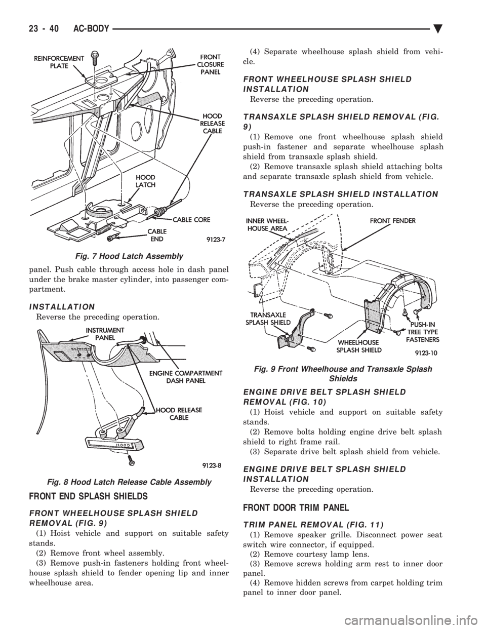
FRONT WHEELHOUSE SPLASH SHIELD REMOVAL (FIG. 9)
(1) Hoist vehicle and support on suitable safety
stands. (2) Remove front wheel assembly.
(3) Remove push-in fasteners holding front wheel-
house splash shield to fender opening lip and inner
wheelhouse area. (4) Separate wheelhouse splash shield from vehi-
cle.
FRONT WHEELHOUSE SPLASH SHIELD INSTALLATION
Reverse the preceding operation.
TRANSAXLE SPLASH SHIELD REMOVAL (FIG.9)
(1) Remove one front wheelhouse splash shield
push-in fastener and separate wheelhouse splash
shield from transaxle splash shield. (2) Remove transaxle splash shield attaching bolts
and separate transaxle splash shield from vehicle.
TRANSAXLE SPLASH SHIELD INSTALLATION
Reverse the preceding operation.
ENGINE DRIVE BELT SPLASH SHIELD REMOVAL (FIG. 10)
(1) Hoist vehicle and support on suitable safety
stands. (2) Remove bolts holding engine drive belt splash
shield to right frame rail. (3) Separate drive belt splash shield from vehicle.
ENGINE DRIVE BELT SPLASH SHIELDINSTALLATION
Reverse the preceding operation.
FRONT DOOR TRIM PANEL
TRIM PANEL REMOVAL (FIG. 11)
(1) Remove speaker grille. Disconnect power seat
switch wire connector, if equipped. (2) Remove courtesy lamp lens.
(3) Remove screws holding arm rest to inner door
panel. (4) Remove hidden screws from carpet holding trim
panel to inner door panel.
Fig. 7 Hood Latch Assembly
Fig. 8 Hood Latch Release Cable Assembly
Fig. 9 Front Wheelhouse and Transaxle Splash Shields
23 - 40 AC-BODY Ä