1993 CHEVROLET DYNASTY open hood
[x] Cancel search: open hoodPage 658 of 2438
EXTERIOR LAMPSÐAJ BODY INDEX
page page
Back-Up Lamp .......................... 17
Back-Up Lamp Bulb ...................... 17
Center High Mounted Stop Lamp (CHMSL) Bulb . 18
Center High-Mounted Stop Lamp Assembly (CHMSL) ............................. 18
Cornering Lamp or Bulb ................... 16
Front Side Marker Lamp ................... 16
Front Side Marker Lamp Bulb ............... 16
Headlamp Module and Bulb ................ 16 Headlamps
............................. 16
License Plate Lamp or Bulb ................ 17
Park and Turn Signal Lamp or Bulb .......... 16
Rear Side Marker Lamp ................... 17
Rear Side Marker Lamp Bulb ............... 17
Tail, Stop, Turn Signal Bulb or Lamp ......... 17
Trunk Lid Tail Lamp ...................... 17
Trunk Lid Tail Lamp Bulb .................. 17
HEADLAMPS
HEADLAMP MODULE AND BULB
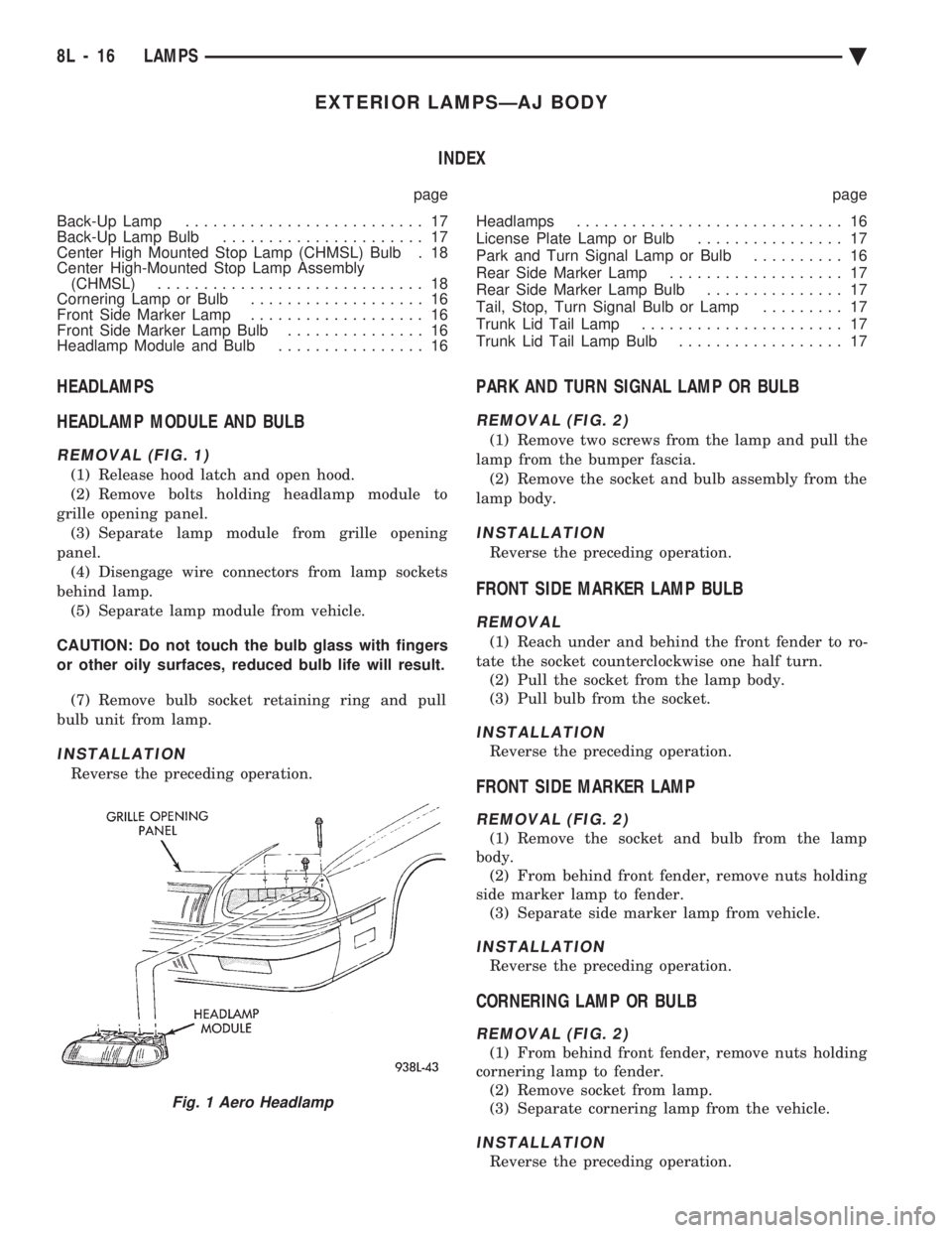
REMOVAL (FIG. 1)
(1) Release hood latch and open hood.
(2) Remove bolts holding headlamp module to
grille opening panel. (3) Separate lamp module from grille opening
panel. (4) Disengage wire connectors from lamp sockets
behind lamp. (5) Separate lamp module from vehicle.
CAUTION: Do not touch the bulb glass with fingers
or other oily surfaces, reduced bulb life will result. (7) Remove bulb socket retaining ring and pull
bulb unit from lamp.
INSTALLATION
Reverse the preceding operation.
PARK AND TURN SIGNAL LAMP OR BULB
REMOVAL (FIG. 2)
(1) Remove two screws from the lamp and pull the
lamp from the bumper fascia. (2) Remove the socket and bulb assembly from the
lamp body.
INSTALLATION
Reverse the preceding operation.
FRONT SIDE MARKER LAMP BULB
REMOVAL
(1) Reach under and behind the front fender to ro-
tate the socket counterclockwise one half turn. (2) Pull the socket from the lamp body.
(3) Pull bulb from the socket.
INSTALLATION
Reverse the preceding operation.
FRONT SIDE MARKER LAMP
REMOVAL (FIG. 2)
(1) Remove the socket and bulb from the lamp
body. (2) From behind front fender, remove nuts holding
side marker lamp to fender. (3) Separate side marker lamp from vehicle.
INSTALLATION
Reverse the preceding operation.
CORNERING LAMP OR BULB
REMOVAL (FIG. 2)
(1) From behind front fender, remove nuts holding
cornering lamp to fender. (2) Remove socket from lamp.
(3) Separate cornering lamp from the vehicle.
INSTALLATION
Reverse the preceding operation.
Fig. 1 Aero Headlamp
8L - 16 LAMPS Ä
Page 664 of 2438
EXTERIOR LAMPSÐAY-BODY INDEX
page page
Center High Mounted Stop Lamp ............ 24
Center High Mounted Stop Lamp Bulb (CHMSL) . 24
Cornering Lamp or BulbÐAY/C-P-Body ........ 24
Front Side Marker BulbÐAY/C-P-Body ........ 23
Front Side Marker LampÐAY/C-P-Body ....... 23
General Information ....................... 22
Headlamp Diagnosis ...................... 22 Headlamps
............................. 22
License Plate Lamp or BulbÐAY/C-P-Body ..... 24
Park, Turn Signal Lamp or BulbÐAY/C-P-Body . . 22
Sealed Beam ........................... 22
Tail, Stop, Turn Signal, Side Marker and Back-Up Lamp or BulbÐAY/C-P-Body .............. 24
GENERAL INFORMATION
To service exterior lamps on AY/C-S-Body, refer to
procedures covered in Exterior LampsÐAC-Body sec-
tion. AC/C-S-Body uses the same lamps as AY/C-S-
Body.
HEADLAMPS
Conventional and halogen sealed beams are inter-
changeable, It is not recommended that they be
mixed. The lens, filament and reflector of sealed
beams are molded into one unit.
HEADLAMP DIAGNOSIS
For headlamp diagnosis, refer to the headlamp di-
agnosis chart at the beginning of this Group. Refer to
Wiring Diagrams manual for circuit and component
locations.
SEALED BEAM
REMOVAL
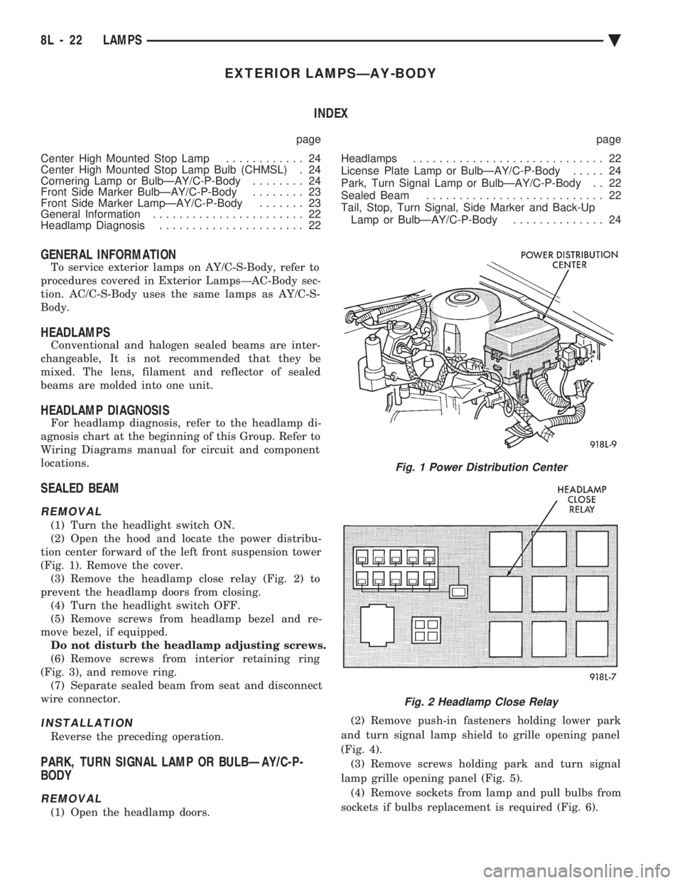
(1) Turn the headlight switch ON.
(2) Open the hood and locate the power distribu-
tion center forward of the left front suspension tower
(Fig. 1). Remove the cover. (3) Remove the headlamp close relay (Fig. 2) to
prevent the headlamp doors from closing. (4) Turn the headlight switch OFF.
(5) Remove screws from headlamp bezel and re-
move bezel, if equipped. Do not disturb the headlamp adjusting screws.
(6) Remove screws from interior retaining ring
(Fig. 3), and remove ring. (7) Separate sealed beam from seat and disconnect
wire connector.
INSTALLATION
Reverse the preceding operation.
PARK, TURN SIGNAL LAMP OR BULBÐAY/C-P-
BODY
REMOVAL
(1) Open the headlamp doors. (2) Remove push-in fasteners holding lower park
and turn signal lamp shield to grille opening panel
(Fig. 4). (3) Remove screws holding park and turn signal
lamp grille opening panel (Fig. 5). (4) Remove sockets from lamp and pull bulbs from
sockets if bulbs replacement is required (Fig. 6).
Fig. 1 Power Distribution Center
Fig. 2 Headlamp Close Relay
8L - 22 LAMPS Ä
Page 669 of 2438
CONCEALED HEADLAMPS INDEX
page page
Concealed Headlamp MotorÐAC-Body ........ 29
Diagnostic Procedures ..................... 27
General Information ....................... 27 Headlamp DoorÐAC-Body
................. 29
Headlamp DoorÐAY Body ................. 29
Headlamp Drive MotorÐAY Body ............ 30
GENERAL INFORMATION
For proper operation of the Concealed Headlamp
System, refer to the Owner's Manual provided with
the vehicle.
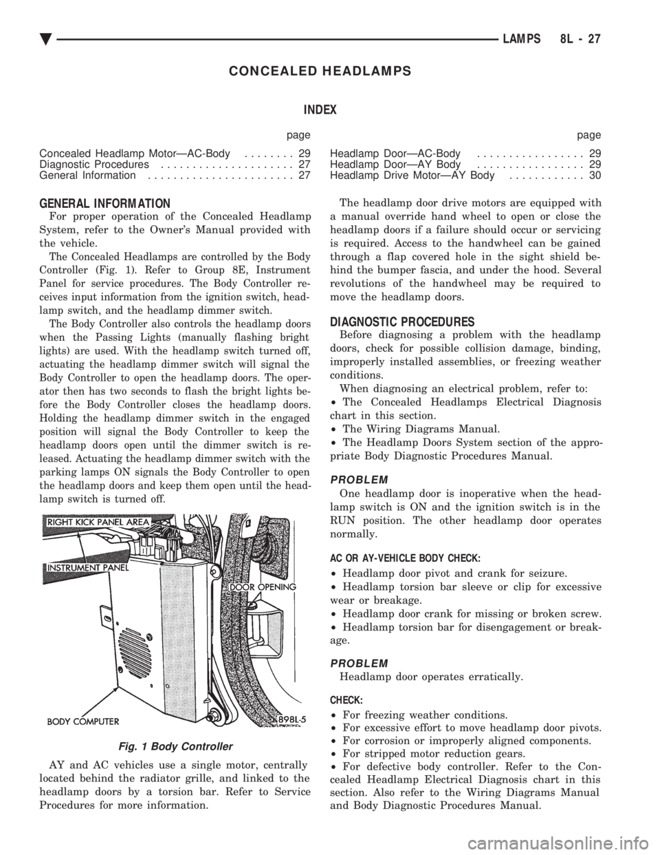
The Concealed Headlamps are controlled by the Body
Controller (Fig. 1). Refer to Group 8E, Instrument
Panel for service procedures. The Body Controller re-
ceives input information from the ignition switch, head-
lamp switch, and the headlamp dimmer switch. The Body Controller also controls the headlamp doors
when the Passing Lights (manually flashing bright
lights) are used. With the headlamp switch turned off,
actuating the headlamp dimmer switch will signal the
Body Controller to open the headlamp doors. The oper-
ator then has two seconds to flash the bright lights be-
fore the Body Controller closes the headlamp doors.
Holding the headlamp dimmer switch in the engaged
position will signal the Body Controller to keep the
headlamp doors open until the dimmer switch is re-
leased. Actuating the headlamp dimmer switch with the
parking lamps ON signals the Body Controller to open
the headlamp doors and keep them open until the head-
lamp switch is turned off.
AY and AC vehicles use a single motor, centrally
located behind the radiator grille, and linked to the
headlamp doors by a torsion bar. Refer to Service
Procedures for more information. The headlamp door drive motors are equipped with
a manual override hand wheel to open or close the
headlamp doors if a failure should occur or servicing
is required. Access to the handwheel can be gained
through a flap covered hole in the sight shield be-
hind the bumper fascia, and under the hood. Several
revolutions of the handwheel may be required to
move the headlamp doors.
DIAGNOSTIC PROCEDURES
Before diagnosing a problem with the headlamp
doors, check for possible collision damage, binding,
improperly installed assemblies, or freezing weather
conditions. When diagnosing an electrical problem, refer to:
² The Concealed Headlamps Electrical Diagnosis
chart in this section.
² The Wiring Diagrams Manual.
² The Headlamp Doors System section of the appro-
priate Body Diagnostic Procedures Manual.
PROBLEM
One headlamp door is inoperative when the head-
lamp switch is ON and the ignition switch is in the
RUN position. The other headlamp door operates
normally.
AC OR AY-VEHICLE BODY CHECK:
² Headlamp door pivot and crank for seizure.
² Headlamp torsion bar sleeve or clip for excessive
wear or breakage.
² Headlamp door crank for missing or broken screw.
² Headlamp torsion bar for disengagement or break-
age.
PROBLEM
Headlamp door operates erratically.
CHECK:
² For freezing weather conditions.
² For excessive effort to move headlamp door pivots.
² For corrosion or improperly aligned components.
² For stripped motor reduction gears.
² For defective body controller. Refer to the Con-
cealed Headlamp Electrical Diagnosis chart in this
section. Also refer to the Wiring Diagrams Manual
and Body Diagnostic Procedures Manual.
Fig. 1 Body Controller
Ä LAMPS 8L - 27
Page 672 of 2438
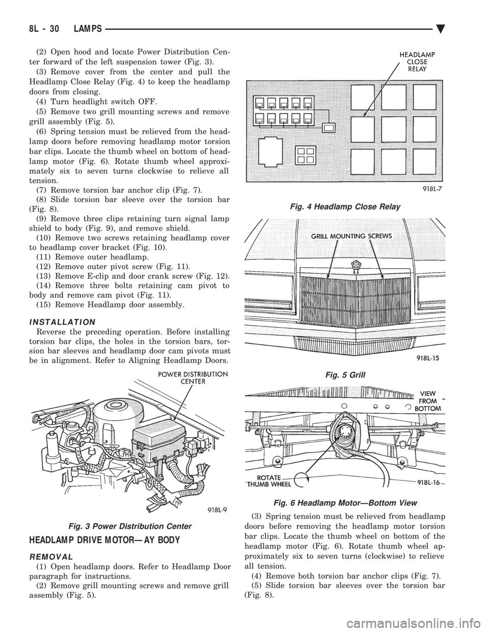
(2) Open hood and locate Power Distribution Cen-
ter forward of the left suspension tower (Fig. 3). (3) Remove cover from the center and pull the
Headlamp Close Relay (Fig. 4) to keep the headlamp
doors from closing. (4) Turn headlight switch OFF.
(5) Remove two grill mounting screws and remove
grill assembly (Fig. 5). (6) Spring tension must be relieved from the head-
lamp doors before removing headlamp motor torsion
bar clips. Locate the thumb wheel on bottom of head-
lamp motor (Fig. 6). Rotate thumb wheel approxi-
mately six to seven turns clockwise to relieve all
tension. (7) Remove torsion bar anchor clip (Fig. 7).
(8) Slide torsion bar sleeve over the torsion bar
(Fig. 8). (9) Remove three clips retaining turn signal lamp
shield to body (Fig. 9), and remove shield. (10) Remove two screws retaining headlamp cover
to headlamp cover bracket (Fig. 10). (11) Remove outer headlamp.
(12) Remove outer pivot screw (Fig. 11).
(13) Remove E-clip and door crank screw (Fig. 12).
(14) Remove three bolts retaining cam pivot to
body and remove cam pivot (Fig. 11). (15) Remove Headlamp door assembly.
INSTALLATION
Reverse the preceding operation. Before installing
torsion bar clips, the holes in the torsion bars, tor-
sion bar sleeves and headlamp door cam pivots must
be in alignment. Refer to Aligning Headlamp Doors.
HEADLAMP DRIVE MOTORÐAY BODY
REMOVAL
(1) Open headlamp doors. Refer to Headlamp Door
paragraph for instructions. (2) Remove grill mounting screws and remove grill
assembly (Fig. 5). (3) Spring tension must be relieved from headlamp
doors before removing the headlamp motor torsion
bar clips. Locate the thumb wheel on bottom of the
headlamp motor (Fig. 6). Rotate thumb wheel ap-
proximately six to seven turns (clockwise) to relieve
all tension. (4) Remove both torsion bar anchor clips (Fig. 7).
(5) Slide torsion bar sleeves over the torsion bar
(Fig. 8).
Fig. 3 Power Distribution Center
Fig. 4 Headlamp Close Relay
Fig. 5 Grill
Fig. 6 Headlamp MotorÐBottom View
8L - 30 LAMPS Ä
Page 684 of 2438

FRONT IMPACT SENSORS
The driver air bag system is a safety device de-
signed to reduce the risk of fatality or serious injury,
caused by a frontal impact of the vehicle. The impact sensors provide verification of the di-
rection and severity of the impact. Three impact sen-
sors are used. One is called a safing sensor. It is
located inside the diagnostic module which is
mounted on the floor pan, just forward of the center
console. The other two sensors are mounted on the
upper crossmember of the radiator closure panel on
the left and right side of the vehicle under the hood. The impact sensors are threshold sensitive switches
that complete an electrical circuit when an impact
provides a sufficient G force to close the switch. The
sensors are calibrated for the specific vehicle and re-
act to the severity and direction of the impact.
CLOCKSPRING
The clockspring is mounted on the steering column
behind the steering wheel, and is used to maintain a
continuous electrical circuit between the wiring har-
ness and the driver's air bag module. This assembly
consists of a flat ribbon-like electrically conductive
tape which winds and unwinds with the steering
wheel rotation.
DIAGNOSTIC MODULE
The Air Bag System Diagnostic Module (ASDM)
contains the safing sensor and energy reserve capac-
itor. The ASDM monitors the system to determine
the system readiness. The ASDM will store sufficient
energy to deploy the air bag for only two minutes af-
ter the battery is disconnected. If both front impact
sensors are open the air bag could be deployed up to
9.5 minutes after the battery is disconnected. The
ASDM contains on-board diagnostics, and will illumi-
nate the AIR BAG warning lamp in the cluster when
a fault occurs.
STORAGE
The air bag module must be stored in its original
special container until used for service. Additionally,
it must be stored in a clean, dry environment, away
from sources of extreme heat, sparks, and sources of
high electrical energy. Always place or store the
module on a surface with the trim cover facing up to
minimize movement in case of accidental deploy-
ment.
HANDLING LIVE MODULE
At no time should any source of electricity be per-
mitted near the inflator on the back of the module.
When carrying a live module, the trim cover should
be pointed away from the body to minimize injury in
the event of accidental deployment. In addition, if
the module is placed on a bench or other surface, the plastic trim cover should be face up to minimize
movement in case of accidental deployment. When handling a steering column with an air bag
module attached, never place the column on the floor
or other surface with the steering wheel or module
face down.
DEPLOYED MODULE
The vehicle interior may contain a very small
amount of sodium hydroxide powder, a byproduct of
air bag deployment. Since this powder can irritate
the skin, eyes, nose or throat, be sure to wear safety
glasses, rubber gloves and long sleeves during
cleanup (Fig. 2).
If you find that the cleanup is irritating your skin,
run cool water over the affected area. Also, if you ex-
perience nasal or throat irritation, exit the vehicle
for fresh air until the irritation ceases. If irritation
continues, see a physician.
CLEANUP PROCEDURE
Begin the cleanup by putting tape over the two air
bag exhaust vents (Fig. 3) so that no additional pow-
der will find its way into the vehicle interior. Then
remove the air bag and air bag module from the ve-
hicle. Use a vacuum cleaner to remove any residual pow-
der from the vehicle interior. Work from the outside
in so that you avoid kneeling or sitting in a un-
cleaned area. Be sure to vacuum the heater and A/C outlets as
well (Fig. 4). In fact it's a good idea to run the blower
on low and to vacuum up any powder expelled from
the plenum. You may need to vacuum the interior of
the car a second time to recover all of the powder. Place the deployed bag and module in your auto-
motive scrap.
Fig. 2 Wear Safety Glasses and Rubber Gloves
8M - 2 RESTRAINT SYSTEMS Ä
Page 703 of 2438

VEHICLE THEFT SECURITY SYSTEM
CONTENTS
page page
GENERAL INFORMATION .................. 1
SECURITY SYSTEM DOOR SWITCH REPLACEMENT ........................ 2
SECURITY SYSTEM HOOD SWITCH REPLACEMENT ........................ 2 SYSTEM SELF-TESTS
.................... 1
VEHICLE THEFT SECURITY SYSTEM MODULE REPLACEMENT ........................ 2
WHAT WILL TRIGGER THE SYSTEM ........ 1
GENERAL INFORMATION
JUMP-STARTING, VEHICLE EQUIPPED
WITH THEFT SECURITY SYSTEM . After the
booster battery has been connected, the Theft System
must be turned OFF. Using the key, lock then un-
lock either front door. This turns the Theft System
OFF and the remainder of the Jump-Starting proce-
dure can be followed. If this procedure is not followed, the Theft System
electronics will prevent the engine from starting. If a new Powertrain Control Module is installed,
the engine has to be cranked 20 times before the
alarm system activated. This passive system is designed to protect against
whole vehicle theft. The system monitors vehicle
doors, hood, trunk key cylinder, and ignition action
for unauthorized operation. The alarm activates by
sounding the horn, flashing the park and tail lamps,
and providing an engine kill feature (Fig. 1). Passive arming occurs upon normal vehicle exit,
open door, lock with power locks, close door. The SET
lamp in the panel will flash for 15 seconds, indicat-
ing that arming is in progress. If no monitored sys-
tems are activated during this period, the system
will arm. If the hood or trunk key cylinder switches
are not sensed by the system. The SET lamp will re-
main lit during the arming process, although the sys-
tem will still arm. The system is to be considered as
an active armed system when using the Remote Key-
less Entry. If the SET lamp does not illuminate at all
upon door closing it indicates that the system is not
arming. Passive disarming occurs upon normal vehicle en-
try unlocking either door with the key, or unlocking
using the Remote Keyless transmitter. This disarm-
ing will also halt the alarm once it has been acti-
vated. Whenever the battery is disconnected and recon-
nected, the Vehicle Theft Security System enters
power up alarm mode which flashes the park and tail
lamps and prevents the engine from running. To exit
this mode, the system must be disarmed as men-
tioned above. A tamper alert exists to notify the driver that the
alarm had been activated, and the alarm has since
timed-out for more than 18 minutes. This alert con-
sists of 3 horn pulses when the vehicle is disarmed. The alarm system will not arm if the doors are
manually locked, providing a manual override of the
alarm.
WHAT WILL TRIGGER THE SYSTEM
One of the following actions will trigger the system
while it is armed. Without properly disarming sys-
tem, by using the key or the remote transmitter. (1) Opening the HOOD.
(2) Opening any DOOR.
(3) Removing the TRUNK KEY CYLINDER.
(4) Turning the IGNITION ON.
(5) The ignition switch can be turned to the acces-
sory position without triggering alarm system.
SYSTEM SELF-TESTS
A diagnostics mode is available in the system to
verify operation of all monitored switches or circuits.
To enter diagnostics, cycle the ignition key to the ac-
cessory position 3 times, leaving the key in this po-
sition. Upon entering diagnostics, the park and tail lamps
will begin flashing to verify their operation. In addi-
tion, the horn will sound twice to indicate that the
trunk key cylinder is in its proper position. Return-
ing the ignition to the OFF position will stop the
lamps from flashing while keeping the system in di-
agnostics. While in diagnostics mode, a horn pulse should oc-
cur at each of the following events indicating proper
operation: (1) Beginning with all doors closed, open then close
each door. The horn will sound when the door ajar
switch closes, and then again when the switch opens.
There must b e a 1 second delay between closing and
opening the switch. (2) Open, then close the hood. The horn will sound
when the hood is opened, and again when it is closed.
Ä VEHICLE THEFT SECURITY SYSTEM 8Q - 1
Page 704 of 2438

(3) Activate the power door locks in both the
LOCK and UNLOCK directions. The horn will sound
after each activation. (4) Rotate the key in each of the door lock cylin-
ders to the unlock position. The horn will sound as
the switch closes, and again when it opens. There
must b e a 1 second delay between changing switch
states, or the horn will not sound.
² Press the LOCK button,horn will sound.
² Press the UNLOCK button, horn will sound.
(5) Cycle the key to the ignition RUN position. A
single horn pulse will indicate proper operation of
the ignition input. This will also take the module out
of the diagnostics mode. For any of these tests, if the
switch does not remain open or closed for at least 1
second, the horn will only sound once. The lack of a horn pulse, during any operation, in-
dicates a switch failure. Check for continuity at the
switch, if this is good, check for an open or shorted
wire between the switch and alarm module. Also,
check if a new powertrain control module has been
installed recently. Vehicle Theft Security System will
not function until 20 engine cranks. Whenever a Vehicle Theft Security System mal-
function occurs, first verify that the wire harness is
properly connected to all connectors before starting
normal diagnosis and repair procedures. Refer to Ve-
hicle Theft Security System Diagnosis Chart (Fig. 3).VEHICLE THEFT SECURITY SYSTEM MODULE
REPLACEMENT
If the Vehicle Theft Security System module is be-
ing removed and no replacement module is being in-
stalled, the module wiring must be disconnected
while the engine is running. Failure to do so will
cause a no-start condition (Fig. 3 and 4). (1) Remove lower right instrument panel silencer.
(2) Remove glove box assembly.
(3) Remove three attaching screws mounting the
bracket to instrument panel. (4) Lower bracket and module assembly, to discon-
nect wire connectors. (5) Remove the Remote keyless module so to have
access to the Security Module two screws attaching
module to bracket. (6) For installation reverse above procedures.
SECURITY SYSTEM HOOD SWITCH REPLACEMENT
(1) Remove screw from left inner fender (Fig. 5).
(2) Disconnect wiring.
(3) Remove switch.
(4) For installation reverse above procedures.
SECURITY SYSTEM DOOR SWITCH REPLACEMENT
(1) Remove door trim panel and water shield. Re-
fer to Group 23, Body.
Fig. 1 Vehicle Theft Security System Components
8Q - 2 VEHICLE THEFT SECURITY SYSTEM Ä
Page 1636 of 2438
(c) Remove LEFT insulator through bolt from in-
side wheelhouse or insulator bracket to transmis-
sion screws.
(22) Remove engine.
INSTALLATION
(1) Attach hoist and lower engine into engine com-
partment. (2) Align engine mounts and install but do not
tighten until all mounting bolts have been installed.
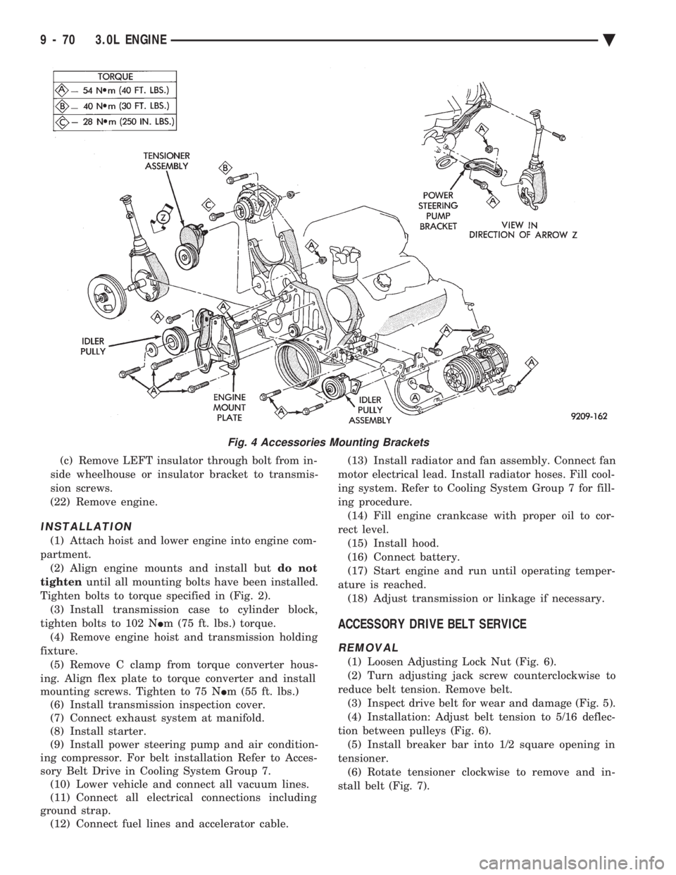
Tighten bolts to torque specified in (Fig. 2). (3) Install transmission case to cylinder block,
tighten bolts to 102 N Im (75 ft. lbs.) torque.
(4) Remove engine hoist and transmission holding
fixture. (5) Remove C clamp from torque converter hous-
ing. Align flex plate to torque converter and install
mounting screws. Tighten to 75 N Im (55 ft. lbs.)
(6) Install transmission inspection cover.
(7) Connect exhaust system at manifold.
(8) Install starter.
(9) Install power steering pump and air condition-
ing compressor. For belt installation Refer to Acces-
sory Belt Drive in Cooling System Group 7. (10) Lower vehicle and connect all vacuum lines.
(11) Connect all electrical connections including
ground strap. (12) Connect fuel lines and accelerator cable. (13) Install radiator and fan assembly. Connect fan
motor electrical lead. Install radiator hoses. Fill cool-
ing system. Refer to Cooling System Group 7 for fill-
ing procedure. (14) Fill engine crankcase with proper oil to cor-
rect level. (15) Install hood.
(16) Connect battery.
(17) Start engine and run until operating temper-
ature is reached. (18) Adjust transmission or linkage if necessary.
ACCESSORY DRIVE BELT SERVICE
REMOVAL
(1) Loosen Adjusting Lock Nut (Fig. 6).
(2) Turn adjusting jack screw counterclockwise to
reduce belt tension. Remove belt. (3) Inspect drive belt for wear and damage (Fig. 5).
(4) Installation: Adjust belt tension to 5/16 deflec-
tion between pulleys (Fig. 6). (5) Install breaker bar into 1/2 square opening in
tensioner. (6) Rotate tensioner clockwise to remove and in-
stall belt (Fig. 7).
Fig. 4 Accessories Mounting Brackets
9 - 70 3.0L ENGINE Ä