1993 CHEVROLET DYNASTY open hood
[x] Cancel search: open hoodPage 2289 of 2438
AY-VEHICLE BODY COMPONENT SERVICE INDEX
page page
A-Pillar and Roof Rail Mouldings ............ 143
B-Pillar Trim Panel ...................... 143
Body Mouldings ......................... 146
Cowl Panel Trim and Scuff Plates ........... 143
Door Frame Trim Moulding ................ 137
Front Door and Hinge .................... 137
Front Door Glass ........................ 139
Front Door Latch ........................ 138
Front Door Silencer and Water Shield ........ 137
Front Door Trim Panel .................... 136
Front Door Window Regulator .............. 138
Front End Splash Shields ................. 136
Front Seat Belts ........................ 144
Front Seats ............................ 145
Grille AY/P Body ........................ 133
Grille AY/S Body ........................ 133
Grille Opening Panel AY/P Body ............ 134
Grille Opening Panel AY/S Body ............ 134
Head Lining ............................ 142
Hood and Hinges ....................... 134
Hood Latch and Release Cable ............. 135
Hood Ornament AY/P-S .................. 134
Outside Door Handle ..................... 138
Overhead Console ....................... 142 Quarter Trim Panel
...................... 143
Rear Deck Filler Panel ................... 146
Rear Door and Hinge .................... 140
Rear Door Fixed Glass Outer Cover ÐAY-S Body ......................... 141
Rear Door Fixed Window Module ........... 142
Rear Door Frame Trim Moulding ............ 139
Rear Door Glass ........................ 141
Rear Door Glass Lift Plate and Guide Bar ..... 141
Rear Door Latch ........................ 140
Rear Door Outer CoverÐAY-P Body ......... 141
Rear Door Outside Handle ................ 140
Rear Door Silencer and Water Shield ........ 140
Rear Door Trim Panel .................... 139
Rear Door Window Regulator .............. 141
Rear Seat Belts ......................... 144
Rear Seats ............................ 145
Rear Shelf Trim Panel .................... 144
Rear Window Glass ...................... 147
Side View Mirror Trim Cover ............... 137
Trunk Lid .............................. 147
Trunk Lid Hinge ........................ 147
Trunk Lid Torsion Bar .................... 148
Vinyl Roof Bonnet ....................... 146
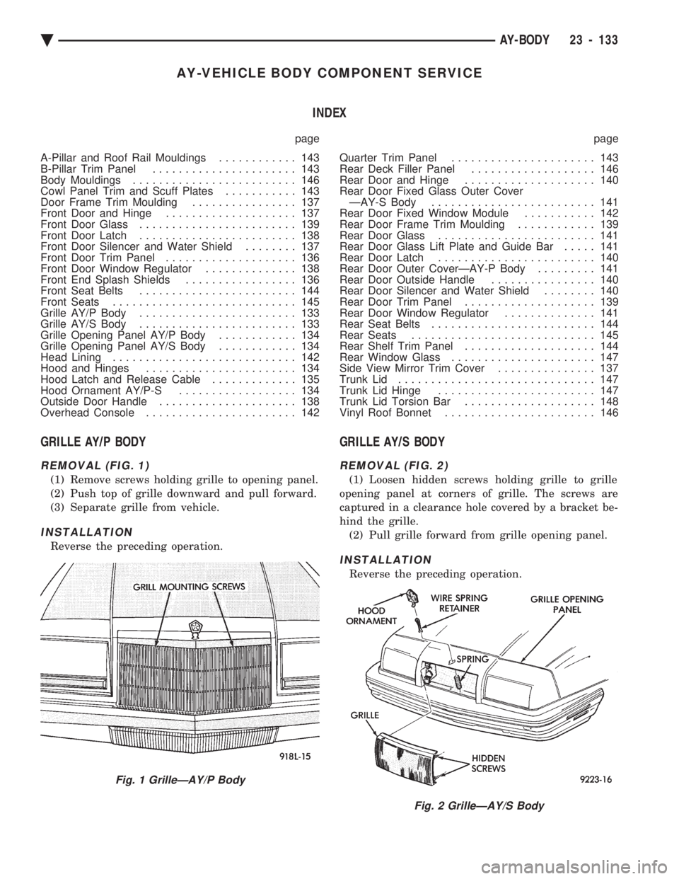
GRILLE AY/P BODY
REMOVAL (FIG. 1)
(1) Remove screws holding grille to opening panel.
(2) Push top of grille downward and pull forward.
(3) Separate grille from vehicle.
INSTALLATION
Reverse the preceding operation.
GRILLE AY/S BODY
REMOVAL (FIG. 2)
(1) Loosen hidden screws holding grille to grille
opening panel at corners of grille. The screws are
captured in a clearance hole covered by a bracket be-
hind the grille. (2) Pull grille forward from grille opening panel.
INSTALLATION
Reverse the preceding operation.
Fig. 1 GrilleÐAY/P Body
Fig. 2 GrilleÐAY/S Body
Ä AY-BODY 23 - 133
Page 2290 of 2438
HOOD ORNAMENT AY/P-S
REMOVAL (FIG. 2)
(1) Remove grille.
(2) Locate hood ornament spring under grille open-
ing panel header. (3) Compress hood ornament spring enough to
clear hooks on end of retaining wire. (4) Squeeze retainer wire hooks together and push
hooks inside spring. (5) Rotate spring counterclockwise to separate
spring from retainer. (6) Separate hood ornament from grille opening
panel.
INSTALLATION
Reverse the preceding operation.
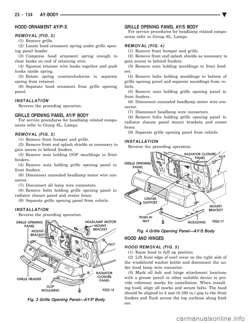
GRILLE OPENING PANEL AY/P BODY
For service procedures for headlamp related compo-
nents refer to Group 8L, Lamps.
REMOVAL (FIG. 3)
(1) Remove front bumper and grille.
(2) Remove front end splash shields as necessary to
gain access to behind fenders. (3) Remove nuts holding GOP mouldings to front
fenders. (4) Remove nuts holding grille opening panel to
front fenders. (6) Disconnect concealed headlamp motor wire con-
nector. (7) Disconnect all lamp wire connectors.
(8) Remove bolts holding grille opening panel to
radiator closure panel and center brace. (9) Separate grille opening panel from vehicle.
INSTALLATION
Reverse the preceding operation.
GRILLE OPENING PANEL AY/S BODY
For service procedures for headlamp related compo-
nents refer to Group 8L, Lamps.
REMOVAL (FIG. 4)
(1) Remove front bumper and grille.
(2) Remove front end splash shields as necessary to
gain access to behind fenders. (3) Remove nuts holding mouldings to front fend-
ers. (4) Remove bolts holding mouldings to bottom of
grille opening panel and separate mouldings from ve-
hicle. (5) Remove nuts holding grille opening panel to
front fenders. (6) Disconnect concealed headlamp motor wire con-
nector. (7) Disconnect headlamp wire connectors.
(8) Remove bolts holding grille opening panel to
radiator closure panel mount brackets and center
brace. (9) Separate grille opening panel from vehicle.
INSTALLATION
Reverse the preceding operation.
HOOD AND HINGES
HOOD REMOVAL (FIG. 5)
(1) Raise hood to full up position.
(2) Lift front edge of cowl cover on the right side of
the windshield washer bottle and disconnect the un-
der hood lamp wire connector. (3) Mark all bolt and hinge attachment locations
with a grease pencil or other suitable device to pro-
vide reference marks for installation. When install-
ing hood, align all marks and secure bolts. The hood
should be aligned to 4 mm (0.160 in.) gap to the front
fenders and flush across the top surfaces along fend-
ers.
Fig. 3 Grille Opening PanelÐAY/P Body
Fig. 4 Grille Opening PanelÐAY/S Body
23 - 134 AY-BODY Ä
Page 2292 of 2438
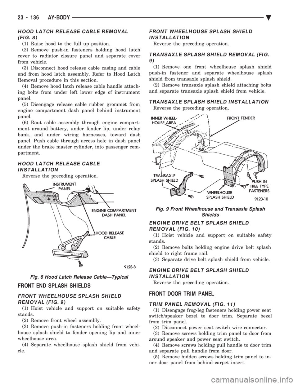
HOOD LATCH RELEASE CABLE REMOVAL (FIG. 8)
(1) Raise hood to the full up position.
(2) Remove push-in fasteners holding hood latch
cover to radiator closure panel and separate cover
from vehicle. (3) Disconnect hood release cable casing and cable
end from hood latch assembly. Refer to Hood Latch
Removal procedure in this section. (4) Remove hood latch release cable handle attach-
ing bolts from under left lower edge of instrument
panel. (5) Disengage release cable rubber grommet from
engine compartment dash panel behind instrument
panel. (6) Rout cable assembly through engine compart-
ment around battery, under fender lip, under relay
bank, and under wiring harnesses, toward dash
panel. Push cable through access hole in dash panel
under the brake master cylinder, into passenger com-
partment.
HOOD LATCH RELEASE CABLE INSTALLATION
Reverse the preceding operation.
FRONT END SPLASH SHIELDS
FRONT WHEELHOUSE SPLASH SHIELDREMOVAL (FIG. 9)
(1) Hoist vehicle and support on suitable safety
stands. (2) Remove front wheel assembly.
(3) Remove push-in fasteners holding front wheel-
house splash shield to fender opening lip and inner
wheelhouse area. (4) Separate wheelhouse splash shield from vehi-
cle.
FRONT WHEELHOUSE SPLASH SHIELD INSTALLATION
Reverse the preceding operation.
TRANSAXLE SPLASH SHIELD REMOVAL (FIG.9)
(1) Remove one front wheelhouse splash shield
push-in fastener and separate wheelhouse splash
shield from transaxle splash shield. (2) Remove transaxle splash shield attaching bolts
and separate transaxle splash shield from vehicle.
TRANSAXLE SPLASH SHIELD INSTALLATION
Reverse the preceding operation.
ENGINE DRIVE BELT SPLASH SHIELD REMOVAL (FIG. 10)
(1) Hoist vehicle and support on suitable safety
stands. (2) Remove bolts holding engine drive belt splash
shield to right frame rail. (3) Separate drive belt splash shield from vehicle.
ENGINE DRIVE BELT SPLASH SHIELDINSTALLATION
Reverse the preceding operation.
FRONT DOOR TRIM PANEL
TRIM PANEL REMOVAL (FIG. 11)
(1) Disengage frog-leg fasteners holding power seat
switch/speaker bezel to door trim. Separate bezel
from trim panel. (2) Disconnect power seat switch wire connector.
(3) Remove screws holding trim panel to door from
around speaker and power seat switch. (4) Remove screws holding pull handle to door trim
and separate pull handle from door. (5) Remove hidden screws holding trim panel to in-
ner door panel from behind carpet insert.
Fig. 8 Hood Latch Release CableÐTypical
Fig. 9 Front Wheelhouse and Transaxle Splash Shields
23 - 136 AY-BODY Ä
Page 2353 of 2438
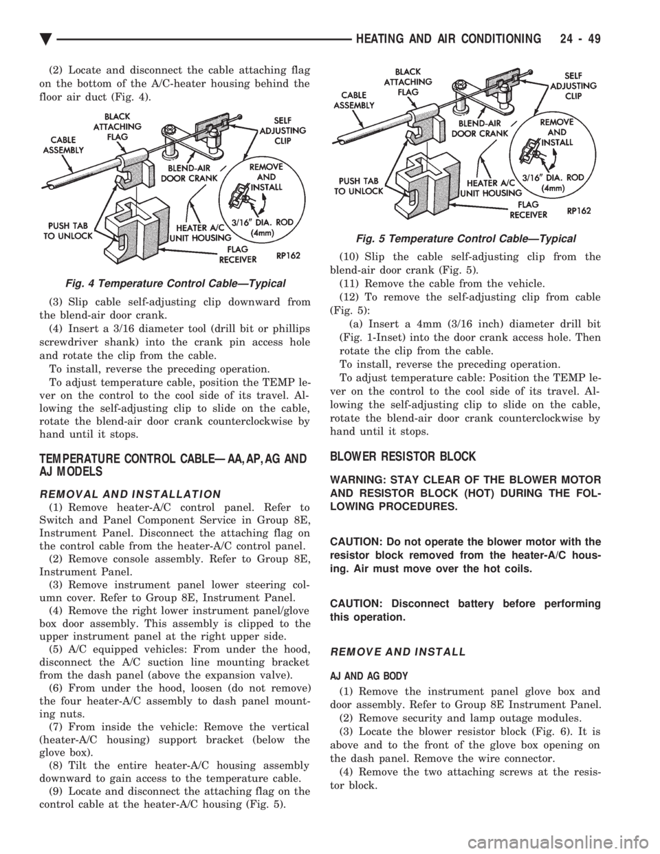
(2) Locate and disconnect the cable attaching flag
on the bottom of the A/C-heater housing behind the
floor air duct (Fig. 4).
(3) Slip cable self-adjusting clip downward from
the blend-air door crank. (4) Insert a 3/16 diameter tool (drill bit or phillips
screwdriver shank) into the crank pin access hole
and rotate the clip from the cable. To install, reverse the preceding operation.
To adjust temperature cable, position the TEMP le-
ver on the control to the cool side of its travel. Al-
lowing the self-adjusting clip to slide on the cable,
rotate the blend-air door crank counterclockwise by
hand until it stops.
TEMPERATURE CONTROL CABLEÐAA,AP,AG AND
AJ MODELS
REMOVAL AND INSTALLATION
(1) Remove heater-A/C control panel. Refer to
Switch and Panel Component Service in Group 8E,
Instrument Panel. Disconnect the attaching flag on
the control cable from the heater-A/C control panel. (2) Remove console assembly. Refer to Group 8E,
Instrument Panel. (3) Remove instrument panel lower steering col-
umn cover. Refer to Group 8E, Instrument Panel. (4) Remove the right lower instrument panel/glove
box door assembly. This assembly is clipped to the
upper instrument panel at the right upper side. (5) A/C equipped vehicles: From under the hood,
disconnect the A/C suction line mounting bracket
from the dash panel (above the expansion valve). (6) From under the hood, loosen (do not remove)
the four heater-A/C assembly to dash panel mount-
ing nuts. (7) From inside the vehicle: Remove the vertical
(heater-A/C housing) support bracket (below the
glove box). (8) Tilt the entire heater-A/C housing assembly
downward to gain access to the temperature cable. (9) Locate and disconnect the attaching flag on the
control cable at the heater-A/C housing (Fig. 5). (10) Slip the cable self-adjusting clip from the
blend-air door crank (Fig. 5). (11) Remove the cable from the vehicle.
(12) To remove the self-adjusting clip from cable
(Fig. 5): (a) Insert a 4mm (3/16 inch) diameter drill bit
(Fig. 1-Inset) into the door crank access hole. Then
rotate the clip from the cable.
To install, reverse the preceding operation.
To adjust temperature cable: Position the TEMP le-
ver on the control to the cool side of its travel. Al-
lowing the self-adjusting clip to slide on the cable,
rotate the blend-air door crank counterclockwise by
hand until it stops.
BLOWER RESISTOR BLOCK
WARNING: STAY CLEAR OF THE BLOWER MOTOR
AND RESISTOR BLOCK (HOT) DURING THE FOL-
LOWING PROCEDURES.
CAUTION: Do not operate the blower motor with the
resistor block removed from the heater-A/C hous-
ing. Air must move over the hot coils.
CAUTION: Disconnect battery before performing
this operation.
REMOVE AND INSTALL
AJ AND AG BODY
(1) Remove the instrument panel glove box and
door assembly. Refer to Group 8E Instrument Panel. (2) Remove security and lamp outage modules.
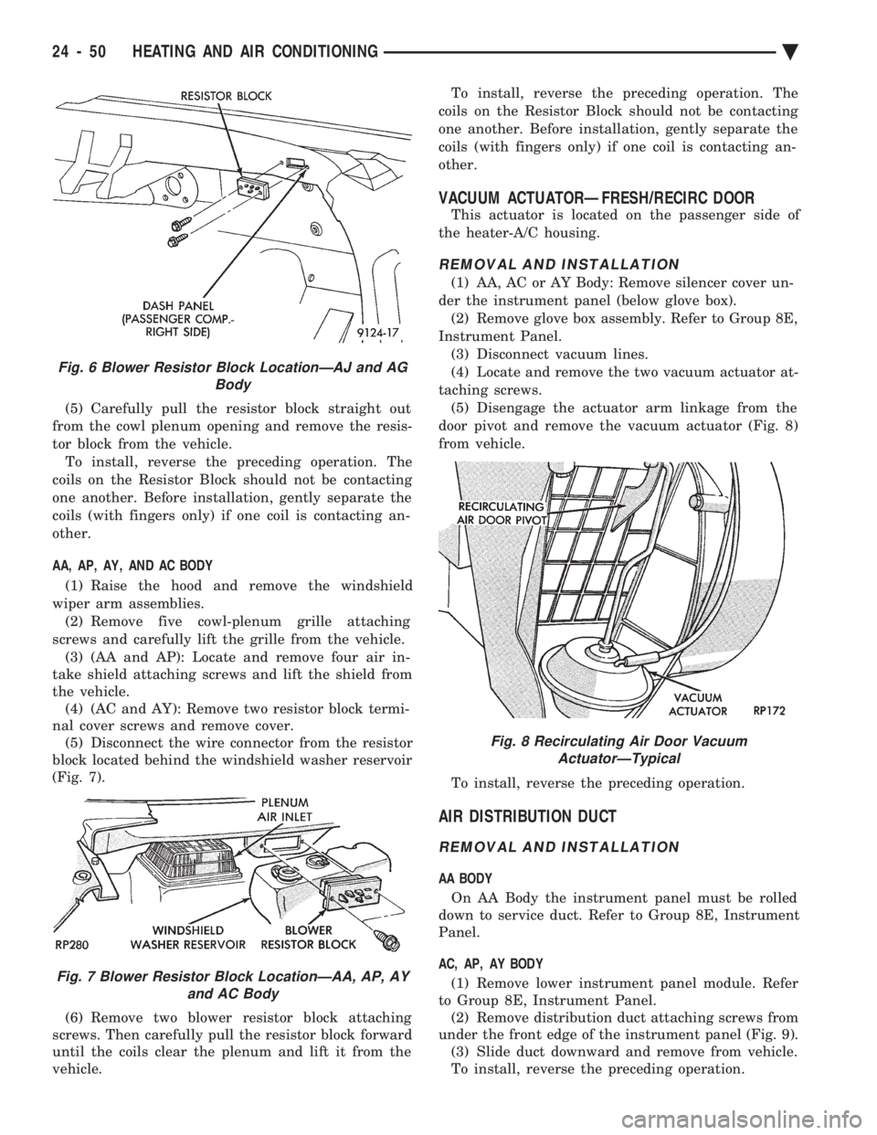
(3) Locate the blower resistor block (Fig. 6). It is
above and to the front of the glove box opening on
the dash panel. Remove the wire connector. (4) Remove the two attaching screws at the resis-
tor block.
Fig. 4 Temperature Control CableÐTypical
Fig. 5 Temperature Control CableÐTypical
Ä HEATING AND AIR CONDITIONING 24 - 49
Page 2354 of 2438
(5) Carefully pull the resistor block straight out
from the cowl plenum opening and remove the resis-
tor block from the vehicle. To install, reverse the preceding operation. The
coils on the Resistor Block should not be contacting
one another. Before installation, gently separate the
coils (with fingers only) if one coil is contacting an-
other.
AA, AP, AY, AND AC BODY
(1) Raise the hood and remove the windshield
wiper arm assemblies. (2) Remove five cowl-plenum grille attaching
screws and carefully lift the grille from the vehicle. (3) (AA and AP): Locate and remove four air in-
take shield attaching screws and lift the shield from
the vehicle. (4) (AC and AY): Remove two resistor block termi-
nal cover screws and remove cover. (5) Disconnect the wire connector from the resistor
block located behind the windshield washer reservoir
(Fig. 7).
(6) Remove two blower resistor block attaching
screws. Then carefully pull the resistor block forward
until the coils clear the plenum and lift it from the
vehicle. To install, reverse the preceding operation. The
coils on the Resistor Block should not be contacting
one another. Before installation, gently separate the
coils (with fingers only) if one coil is contacting an-
other.
VACUUM ACTUATORÐFRESH/RECIRC DOOR
This actuator is located on the passenger side of
the heater-A/C housing.
REMOVAL AND INSTALLATION
(1) AA, AC or AY Body: Remove silencer cover un-
der the instrument panel (below glove box). (2) Remove glove box assembly. Refer to Group 8E,
Instrument Panel. (3) Disconnect vacuum lines.
(4) Locate and remove the two vacuum actuator at-
taching screws. (5) Disengage the actuator arm linkage from the
door pivot and remove the vacuum actuator (Fig. 8)
from vehicle.
To install, reverse the preceding operation.
AIR DISTRIBUTION DUCT
REMOVAL AND INSTALLATION
AA BODY On AA Body the instrument panel must be rolled
down to service duct. Refer to Group 8E, Instrument
Panel.
AC, AP, AY BODY (1) Remove lower instrument panel module. Refer
to Group 8E, Instrument Panel. (2) Remove distribution duct attaching screws from
under the front edge of the instrument panel (Fig. 9). (3) Slide duct downward and remove from vehicle.
To install, reverse the preceding operation.
Fig. 6 Blower Resistor Block LocationÐAJ and AG Body
Fig. 7 Blower Resistor Block LocationÐAA, AP, AYand AC Body
Fig. 8 Recirculating Air Door VacuumActuatorÐTypical
24 - 50 HEATING AND AIR CONDITIONING Ä
Page 2358 of 2438
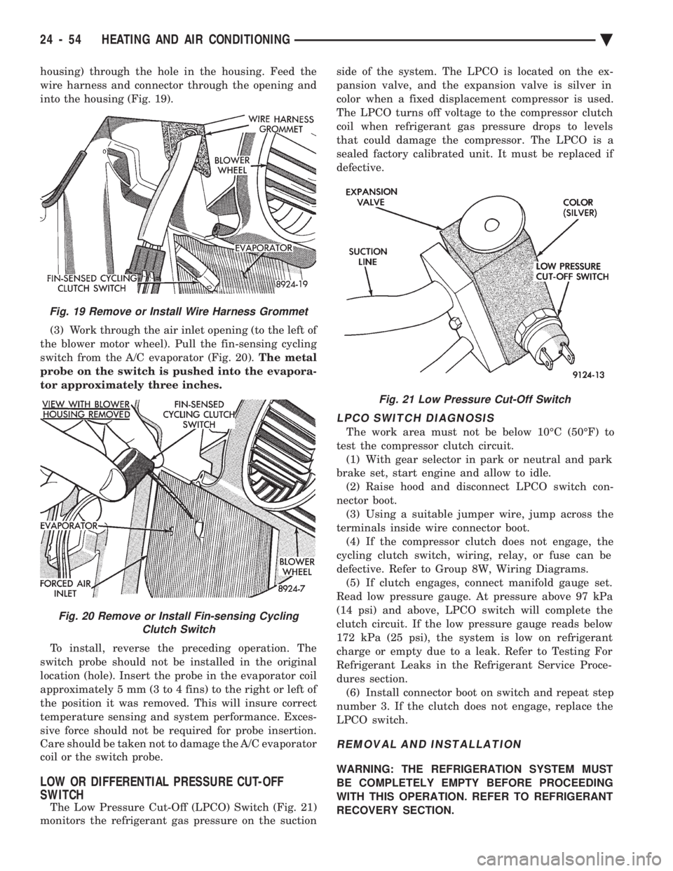
housing) through the hole in the housing. Feed the
wire harness and connector through the opening and
into the housing (Fig. 19). (3) Work through the air inlet opening (to the left of
the blower motor wheel). Pull the fin-sensing cycling
switch from the A/C evaporator (Fig. 20). The metal
probe on the switch is pushed into the evapora-
tor approximately three inches.
To install, reverse the preceding operation. The
switch probe should not be installed in the original
location (hole). Insert the probe in the evaporator coil
approximately 5 mm (3 to 4 fins) to the right or left of
the position it was removed. This will insure correct
temperature sensing and system performance. Exces-
sive force should not be required for probe insertion.
Care should be taken not to damage the A/C evaporator
coil or the switch probe.
LOW OR DIFFERENTIAL PRESSURE CUT-OFF
SWITCH
The Low Pressure Cut-Off (LPCO) Switch (Fig. 21)
monitors the refrigerant gas pressure on the suction side of the system. The LPCO is located on the ex-
pansion valve, and the expansion valve is silver in
color when a fixed displacement compressor is used.
The LPCO turns off voltage to the compressor clutch
coil when refrigerant gas pressure drops to levels
that could damage the compressor. The LPCO is a
sealed factory calibrated unit. It must be replaced if
defective.
LPCO SWITCH DIAGNOSIS
The work area must not be below 10ÉC (50ÉF) to
test the compressor clutch circuit. (1) With gear selector in park or neutral and park
brake set, start engine and allow to idle. (2) Raise hood and disconnect LPCO switch con-
nector boot. (3) Using a suitable jumper wire, jump across the
terminals inside wire connector boot. (4) If the compressor clutch does not engage, the
cycling clutch switch, wiring, relay, or fuse can be
defective. Refer to Group 8W, Wiring Diagrams. (5) If clutch engages, connect manifold gauge set.
Read low pressure gauge. At pressure above 97 kPa
(14 psi) and above, LPCO switch will complete the
clutch circuit. If the low pressure gauge reads below
172 kPa (25 psi), the system is low on refrigerant
charge or empty due to a leak. Refer to Testing For
Refrigerant Leaks in the Refrigerant Service Proce-
dures section. (6) Install connector boot on switch and repeat step
number 3. If the clutch does not engage, replace the
LPCO switch.
REMOVAL AND INSTALLATION
WARNING: THE REFRIGERATION SYSTEM MUST
BE COMPLETELY EMPTY BEFORE PROCEEDING
WITH THIS OPERATION. REFER TO REFRIGERANT
RECOVERY SECTION.
Fig. 21 Low Pressure Cut-Off Switch
Fig. 19 Remove or Install Wire Harness Grommet
Fig. 20 Remove or Install Fin-sensing Cycling Clutch Switch
24 - 54 HEATING AND AIR CONDITIONING Ä
Page 2366 of 2438
AA BODY PROCEDURE
WARNING: IF EQUIPPED WITH A/C, THE REFRIG-
ERATION SYSTEM MUST BE COMPLETELY EMPTY
BEFORE PROCEEDING WITH THIS OPERATION. Refer to Group 8E and Group 23 for component re-
moval and installation when performing this opera-
tion. (1) Perform steps 1 through 7 of Blower Motor re-
moval and installation. (2) Remove relay panel above glove compartment
opening. (3) Disconnect the A/C vacuum line connector and
radio noise capacitor connectors. (4) Remove left windshield pillar trim cover.
(5) Remove left lower side cowl trim cover.
(6) Remove hood release handle mechanism attach-
ing screws. (7) Remove steering column trim covers.
(8) Disconnect parking brake release mechanism
connecting rod. Gain access through fuse panel open-
ing. (9) Remove lower left instrument panel silencer.
(10) Remove lower left instrument panel reinforce-
ment. (11) Remove instrument panel center (radio) bezel.
(12) Remove forward floor console.
(13) Remove the radio.
(14) Remove the heater-A/C control.
(15) Remove cigar lighter.
(16) Remove message center/trip computer, if
equipped. (17) Disconnect side window demister tubes from
top of heat A/C unit. (18) Remove steering column upper attaching bolts
and allow the steering wheel to rest on the driver
seat cushion. (19) Remove upper instrument panel (defroster
outlet) cover. (20) Remove upper instrument panel attaching
screws from below the windshield opening. (21) Loosen (do not remove) the left lower cowl in-
strument panel attaching screw. (22) Remove the right lower cowl instrument panel
attaching screw.
CAUTION: Protect the passenger seat cover from
soiling or damage using a suitable cover.
(23) Carefully pull the right side of the instrument
panel away from the vehicle. Allow the instrument
panel to rest on the passenger seat cushion.
CAUTION: Before proceeding with the next opera-
tion, review the Safety Precautions and Warnings at
the front of this Group. (24) From the engine compartment, drain the cool-
ing system and disconnect the heater hoses from the
heater core nipples. Plug the nipples to avoid spilling
coolant inside the vehicle. (25) Disconnect the refrigerant lines from the ex-
pansion-valve at the dash panel on the right side of
the vehicle. Seal the refrigerant lines to prevent con-
tamination. (26) Remove the expansion valve from the evapo-
rator plate. Seal the valve to avoid contamination. (27) Remove the condensate drain tube.
(28) Remove heater-A/C unit to dash panel attach-
ing nuts. (29) From inside the vehicle, pull rearward on the
heater-A/C unit to clear the dash panel silencer and
remove the unit from the vehicle. To install, reverse the preceding operation. Refill
cooling system and test for leaks. Evacuate and
charge the refrigerant system and test overall perfor-
mance.
AG, AJ BODY PROCEDURE
WARNING: IF EQUIPPED WITH A/C, THE REFRIG-
ERATION SYSTEM MUST BE COMPLETELY EMPTY
BEFORE PROCEEDING WITH THIS OPERATION.
(1) Disconnect the battery negative cable.
(2) Drain the coolant from cooling system. Refer to
Group 7, Cooling System. (3) Remove the air conditioner expansion valve (if
equipped). (4) Disconnect the heater hoses from heater core.
Then plug or cap the tubes on heater core. This will
prevent spilling coolant into the interior of vehicle
during unit removal. (5) Remove the condensate drain tube.
(6) Disconnect the A/C-heater vacuum supply line
from vacuum supply nipple (in the engine compart-
ment). (7) Remove the four A/C-heater assembly-to-dash
panel attaching nuts. (8) Remove the passenger side front seat. Refer to
Group 23, Body. (9) Remove the kick panel/sill cover at right door
opening. (10) Remove the body computer (Fig. 6) located at
the lower right section of the right front door pillar. (11) Remove the glove box assembly. Refer to
Group 8E, Instrument Panel. (12) Remove the carpeted panels from both sides of
the console. (13) Un-clip the radio antenna cable from the
metal support (Fig. 6) located behind and below the
glove box opening. (14) Instrument panel removal is not necessary to
remove the A/C-heater assembly from the vehicle.
24 - 62 HEATING AND AIR CONDITIONING Ä
Page 2377 of 2438
(b) Does the blower motor operate at its highest
speed ? (c) Feel the outlet temperature. Does it get hot
and then cycle cold ? (d) Does the air flow switch from DEFROST out-
lets and then cycle to PANEL outlets?
If you can answer NO to any of these questions,
proceed to step 4, otherwise proceed to step 5. (4) If you answered NO to:
SYMPTOM A
The display symbols and indicators do not illumi-
nate. Diagnostic Trouble Codes are not displayed.
TEST
After self-diagnostic test is complete, select a mode
that will display the malfunction.
ACTION
If the ATC system operates properly, and the dis-
play does not, replace ATC control panel computer.
SYMPTOM B
The blower motor does not operate.
CAUTION: Stay clear of blower motor and power
module (PM) heat sink. Do not run system for more
than 10 minutes with PM removed from A/C unit.
TEST Check all power module and blower motor connec-
tions. Use a voltmeter to test for 12 volts (ignition)
at both ends of the fuse with ignition ON. If fuse is
good, test the green wire at the blower motor connec-
tor for 12 volts (ignition) to body ground. Turn ignition to the ON position.
With the blower motor still connected, check for 12
volts to body ground on the black/tan wire of the
blower motor two way connector. Check for 12 volts at the Power Module pin #4
(BK/TN). Check for continuity from the Power Module pin
#3 (BK) to chassis ground. Replace the Power Module.
ACTION If 12 volts is not detected, repair feed circuit. Refer
to the Front Wheel Drive Car-Wiring Diagrams Ser-
vice Manual. If 12 volts is not detected, repair wires of the
blower motor or replace the blower motor. If 12 volts is not present, repair wire from the
blower motor connector to the Power Module. If circuit is open, repair ground circuit of the Power
Module. Replace the Power Module (power transistor open).
SYMPTOM C
The outlet air temperature does not become hot
and then cycle to cold during self-test operation. Di-
agnostic Trouble Codes are not displayed.
TEST/ACTION
Make sure the blend-air door is properly attached
to the actuator. If cold air is not discharged from the outlets, check
the base A/C refrigerant system. Make sure heating operation works correctly, (wa-
ter level, thermostat, heater hoses, heater core, etc.).
SYMPTOM D
Air does not flow from DEFROST outlets and then
cycle to PANEL outlets during self-test operation.
TEST/ACTION Check linkages from the mode door actuator for
binding. Check for proper door travel in the unit.
(5) The computer will do one of two things:
² Will return to the control settings that were se-
lected before the Diagnostic Test was started. This
means the test is over. If Diagnostic Trouble Codes
did not occur, and answers to questions (a), (b), (c),
and (d) were YES, the entire system is operating cor-
rectly.
² The blower motor will stop and the computer will
flash a Diagnostic Trouble Code number from 01
through 28. Record the number and then depress the
PANEL button to advance to the next test. If the
ATC control flashes one or more codes 23 to 28, the
digits on the display will flash alternating Zeros. If
you do nothing, these codes will remain stored within
the ATC control computer. After all repairs have
been made erase fault codes. Refer to Erasing Diag-
nostic Trouble Codes 23 through 28 from ATC Con-
trol in this section. Repair all Diagnostic Trouble Codes in the order
that they have been indicated, and then retest the
system. If any blend door test fails, all remaining
blend door tests will be skipped. IF any mode door
tests fail, all remaining mode door tests will be
skipped. Diagnostic Test can be stopped at any time by de-
pressing any button other than PANEL.
DIAGNOSTIC TROUBLE CODE DEFINITIONS
Non-computer aided diagnostics should be per-
formed first. Hood of vehicle should be closed during
the diagnostic test to keep engine heat from effecting
the ambient temperature sensor. Also refer to the wiring Pin out charts.
² DIAGNOSTIC TROUBLE CODE 1
Involves the wiring or the ATC control head.
² DIAGNOSTIC TROUBLE CODES 2, 13, 14, 15,
20, and 23
Ä HEATING AND AIR CONDITIONING 24 - 73