1993 CHEVROLET DYNASTY open hood
[x] Cancel search: open hoodPage 549 of 2438

(11) Remove two screws from fuse block and lower
fuse block. (12) Remove three screws from hood release and
lower hood release handle. (13) Remove flasher relay from bracket on center
distribution duct. (14) Remove screw from ATC sensor motor assem-
bly and unhook from bracket if equipped. (15) Remove the radio ground screw above flasher
relay mount. (16) Remove center distribution duct screw from
left instrument panel lower brace, then remove four
screws to remove left lower brace.
(17) Remove five nuts on steering column and drop
column, then remove two upper column attaching studs.
(18) Remove two screws and pull out compact disc
player or cubby box, disconnect Co-Axial cable from
compact disc player. (19) Remove Electronic Vehicle Information Center
(E.V.I.C.) or Traveler from vehicle. (20) Remove radio.
(21) Remove A.T.C., A/C or heater controls. (22) Squeeze latches on side of Rear Window defog-
ger switch and remove. (23) Snap off cluster lower trim bezel, switch pod
vent grille, speaker grilles and defroster grilles. (24) Remove switch pod assembly.
(25) Remove cluster assembly.
(26) Remove dash speakers.
(27) Snap out bezel with or without message center
and disconnect wiring. (28) Open glovebox door, squeeze sides and roll
glovebox completely open. Remove glovebox light
switch, and disconnect wires. (29) Loosen right cowl side pivot bolt through
glovebox opening then close glovebox. (30) Loosen left cowl side pivot.
(31) Remove four screw attachments at top of in-
strument panel and roll panel out. (32) Pull wiring, antenna cable, A/C cable and vac-
uum lines out of instrument panel. Disconnect demis-
ter hose and remove instrument panel with ducts
attached. (33) Transfer ducts and brackets onto new panel.
(34) For instrument panel roll up, reverse
above procedures.
INTERIOR LAMP REMOVAL
The Dome, Floor Console and Door Lamps operate
when the doors are open or headlamp switch is
placed in courtesy position.
DOME LAMP
(1) Pry either the forward or rearward edge of the
dome lamp to free it from retaining bracket. (2) Pry either the forward or rearward edge of the
lens away from the bezel and replace lamp. (3) For installation reverse above procedures.
FRONT HEADER READING LAMP
Pull lamp from headliner. Disconnect wiring and
replace lamp.
FLOOR CONSOLE LAMP
Pry along top edge of lamp and pivot lamp out of
floor console, the lens does not remove. Remove lamp
and twist out lamp socket. Replace lamp.
DOOR LAMPS
Pry along bottom edge of lamp and pivot lamp out
of door trim panel, the lens does not remove. Remove
lamp and twist out lamp socket. Replace lamp.
DOOR REFLECTORS
Pry reflector away from the door trim panel, and
replace.
TRUNK LAMP
Remove lens by prying lens out of trunk trim panel
and replace bulb.
Fig. 33 Transmission Range Cable
Fig. 34 Cable Adjustment
Ä INSTRUMENT PANEL AND GAUGES 8E - 57
Page 559 of 2438

VEHICLE SPEED SENSOR TEST
For testing of the vehicle speed sensor and related
components using DRB II, refer to the appropriate
Powertrain Diagnostics Test Procedure Manual.
PRINTED CIRCUIT BOARD REPLACEMENT
(1) Remove cluster bezel.
(2) Remove instrument cluster.
(3) Remove tachometer drive module, if equipped.
(4) Remove six retaining screws (Fig. 18).
(5) Twist out all illumination and warning lamp
sockets. (6) Pull printed circuit board from cluster housing.
(7) For installation reverse above procedures. Posi-
tion printed circuit board on cluster housing, being
certain that all gauge pins are inserted correctly.
CLUSTER LAMP REPLACEMENT
Illumination Lamp Chart shows cluster as viewed
from rear. However, all lamps must be replaced by
removing cluster from instrument panel (Fig. 19).
SWITCH AND PANEL COMPONENT SERVICE
LOWER STEERING COLUMN COVER REPLACEMENT
(1) Disconnect park brake release rod from the
park brake handle. (2) Remove two screws attaching hood release (Fig.
20). (3) Remove fuse access door and remove steering
column cover attaching screw located directly above
the fuse block. (4) Remove six screws around outside of steering
column cover. (5) Remove steering column cover.
(6) For installation reverse above procedures.
CENTER MODULE LOWER COVER REPLACEMENT
(1) Open ash receiver and remove center module
bezel. (2) Remove module cover to instrument panel re-
taining screws (Fig. 20). (3) Remove module cover from vehicle.
(4) For installation reverse above procedures.
CENTER MODULE BEZEL REPLACEMENT
(1) Open ash receiver.
(2) Grip module bezel around outer edges and pull
rearward to release six spring-type retaining clips
(Fig. 20). (3) For installation position spring clips to instru-
ment panel and push firmly until seated. (4) Close ash receiver.
Fig. 17 Vehicle Speed Sensor Removal
Fig. 18 Printed Circuit Board
Fig. 19 Instrument Cluster Illumination Lamps
Ä INSTRUMENT PANEL AND GAUGES 8E - 67
Page 564 of 2438
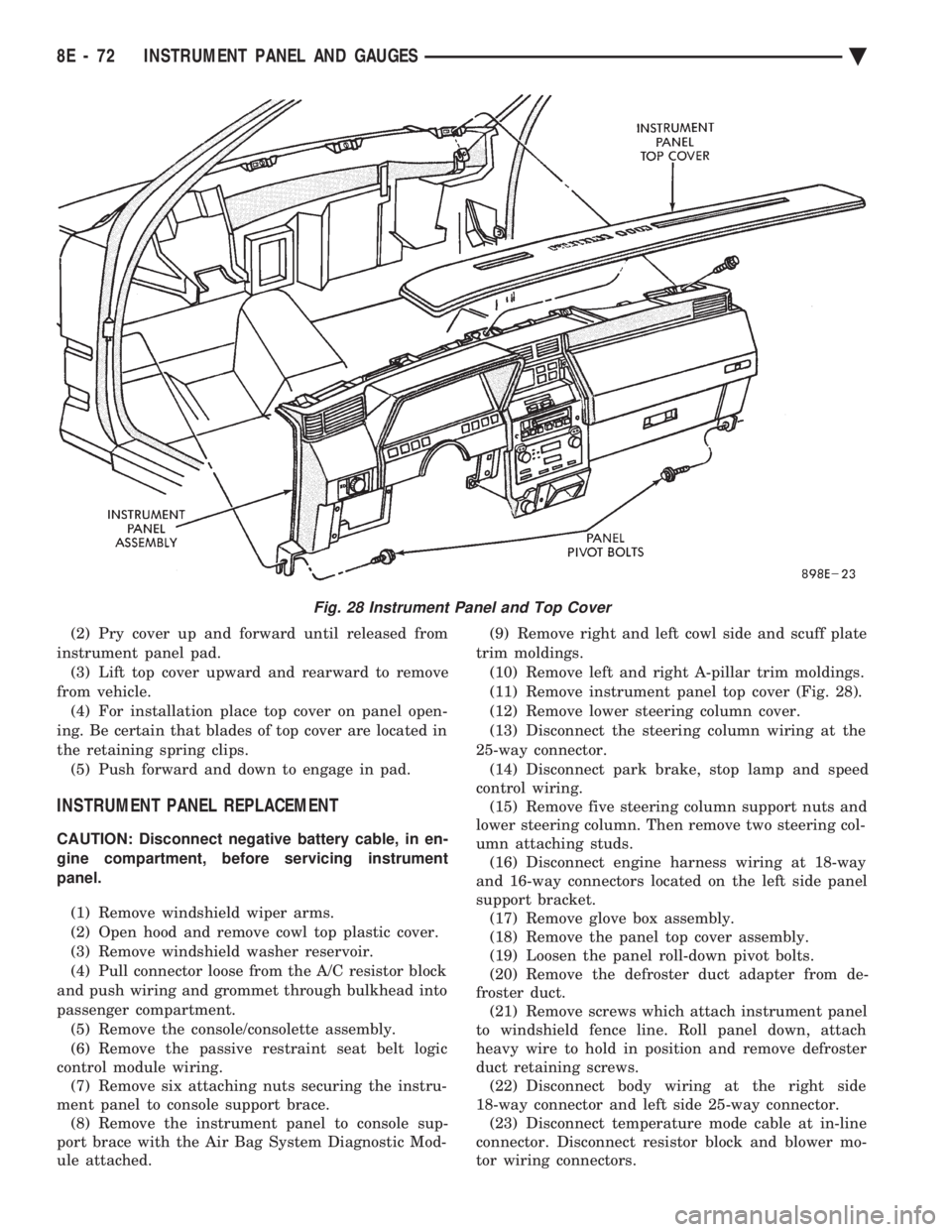
(2) Pry cover up and forward until released from
instrument panel pad. (3) Lift top cover upward and rearward to remove
from vehicle. (4) For installation place top cover on panel open-
ing. Be certain that blades of top cover are located in
the retaining spring clips. (5) Push forward and down to engage in pad.
INSTRUMENT PANEL REPLACEMENT
CAUTION: Disconnect negative battery cable, in en-
gine compartment, before servicing instrument
panel.
(1) Remove windshield wiper arms.
(2) Open hood and remove cowl top plastic cover.
(3) Remove windshield washer reservoir.
(4) Pull connector loose from the A/C resistor block
and push wiring and grommet through bulkhead into
passenger compartment. (5) Remove the console/consolette assembly.
(6) Remove the passive restraint seat belt logic
control module wiring. (7) Remove six attaching nuts securing the instru-
ment panel to console support brace. (8) Remove the instrument panel to console sup-
port brace with the Air Bag System Diagnostic Mod-
ule attached. (9) Remove right and left cowl side and scuff plate
trim moldings. (10) Remove left and right A-pillar trim moldings.
(11) Remove instrument panel top cover (Fig. 28).
(12) Remove lower steering column cover.
(13) Disconnect the steering column wiring at the
25-way connector. (14) Disconnect park brake, stop lamp and speed
control wiring. (15) Remove five steering column support nuts and
lower steering column. Then remove two steering col-
umn attaching studs. (16) Disconnect engine harness wiring at 18-way
and 16-way connectors located on the left side panel
support bracket. (17) Remove glove box assembly.
(18) Remove the panel top cover assembly.
(19) Loosen the panel roll-down pivot bolts.
(20) Remove the defroster duct adapter from de-
froster duct. (21) Remove screws which attach instrument panel
to windshield fence line. Roll panel down, attach
heavy wire to hold in position and remove defroster
duct retaining screws. (22) Disconnect body wiring at the right side
18-way connector and left side 25-way connector. (23) Disconnect temperature mode cable at in-line
connector. Disconnect resistor block and blower mo-
tor wiring connectors.
Fig. 28 Instrument Panel and Top Cover
8E - 72 INSTRUMENT PANEL AND GAUGES Ä
Page 626 of 2438
CONDITION: MOTOR WILL STOP WHEREVER IT IS, WHEN COLUMN SWITCH IS PUT IN OFFPOSITION. THE WIPERS DO NOT CONTINUERUNNING TO PARK POSITION
PROCEDURE
(1) Remove motor wiring connector and clean ter-
minals. Reconnect connector and test motor.If prob-
lem persists, proceed to Step 2. (2) Set wiper switch to OFF position. Disconnect
motor wiring connector. Connect a voltmeter or test
lamp to the motor ground strap. Connect the other
lead to terminal 2 of wiring connector. (a) If voltage is not present, check for an open
circuit in the wiring harness or wiper control
switch. (b) If voltage is present, proceed to step 3.
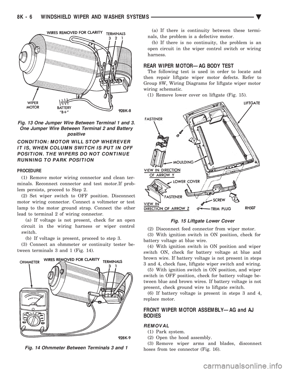
(3) Connect an ohmmeter or continuity tester be-
tween terminals 3 and 1 (Fig. 14). (a) If there is continuity between these termi-
nals, the problem is a defective motor. (b) If there is no continuity, the problem is an
open circuit in the wiper control switch or wiring
harness.
REAR WIPER MOTORÐAG BODY TEST
The following test is used in order to locate and
then repair liftgate wiper motor defects. Refer to
Group 8W, Wiring Diagrams for liftgate wiper motor
wiring schematic. (1) Remove lower cover on liftgate (Fig. 15).
(2) Disconnect feed connector from wiper motor.
(3) With ignition switch in ON position, check for
battery voltage at blue wire. (4) With ignition switch in ON position and wiper
switch ON, check for battery voltage at blue and
brown wire. If battery voltage is not present in steps
3 and 4, check fuse, liftgate wiper switch and wiring. (5) With ignition switch in ON position, and wiper
switch in OFF position, check for battery voltage be-
tween blue and brown wires. If battery voltage is not
present, check ground wire to liftgate switch. (6) If battery voltage is present in steps 3 and 4,
replace motor.
FRONT WIPER MOTOR ASSEMBLYÐAG and AJ
BODIES
REMOVAL
(1) Park system.
(2) Open the hood assembly.
(3) Remove wiper arms and blades, disconnect
hoses from tee connector (Fig. 16).
Fig. 13 One Jumper Wire Between Terminal 1 and 3. One Jumper Wire Between Terminal 2 and Battery positive
Fig. 14 Ohmmeter Between Terminals 3 and 1
Fig. 15 Liftgate Lower Cover
8K - 6 WINDSHIELD WIPER AND WASHER SYSTEMS Ä
Page 628 of 2438
(4) Remove the cowl top plastic screen.
(5) Remove pivot screws.
(6) Remove wiper motor cover and disconnect wiring
harness. (7) Remove three motor mounting nuts.
(8) Push pivots down into plenum chamber and pull
motor out until it clears the mounting studs. Then
move it as far to the drivers side or outboard as it will
go. Pull right pivot and link out through opening. Shift
motor to opposite side or inboard of opening and
remove motor, left link and pivot. (9) Clamp motor crank in a vise and remove nut
from end of motor shaft. Do not rotate motor output
shaft from PARK position.
INSTALLATION
(1) Assemble linkage to motor. Make sure crank fits
over D slot on motor shaft. Tighten mounting nut to 10
to 11 N Im (90 to 100 in. lbs.) torque. Be sure motor is
still in park position before assembling to linkage, if
not temporarily connect motor to wiring and operate
switch to position motor in park before assembling
linkage. (2) Place left pivot and link into plenum chamber.(a) Slide it all the way to the left or outboard side
until motor clears studs and crank is behind sheet
metal. (b) Push right pivot and link through opening.
(c) Move assembly right and position motor on
studs.
(3) Install three motor mounting nuts and tighten 7
to8N Im (60 70 in. lbs.) torque.
(4) Position pivots and install pivot screws and
tighten 7 to 8 N Im (60 to 70 in. lbs.) torque.
(5) Connect wiring to motor.
(6) Install motor cover. Tighten screws to 4 N Im (35
in. lbs.) torque. (7) Attach reservoir hose to T-connector through hole
provided in cowl screen. (8) Use plastic fasteners to install cowl screen.
(9) Install arm and blade assemblies. Refer to Wiper
Arm Adjustment. Connect arm washer hoses to
T-connector.
REAR WIPER MOTOR ASSEMBLYÐAG BODY
REMOVAL
(1) Remove arm and blade assembly, refer to Arm
and Blade Removal. (2) Unlock and open liftgate.
(3) Remove trim panel refer to Group 23, Body.
(4) Disconnect feed wire connector from motor.
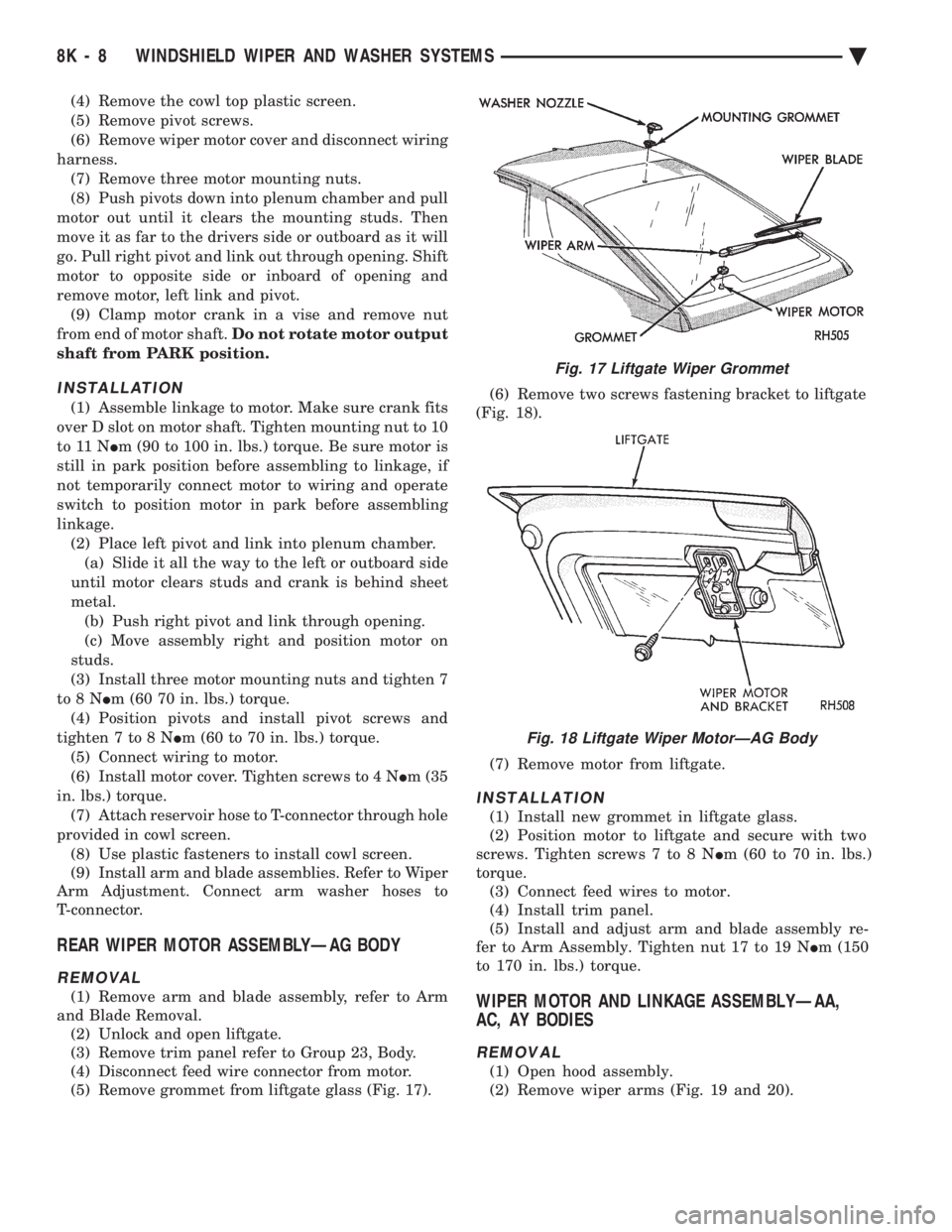
(5) Remove grommet from liftgate glass (Fig. 17). (6) Remove two screws fastening bracket to liftgate
(Fig. 18).
(7) Remove motor from liftgate.
INSTALLATION
(1) Install new grommet in liftgate glass.
(2) Position motor to liftgate and secure with two
screws. Tighten screws 7 to 8 N Im (60 to 70 in. lbs.)
torque. (3) Connect feed wires to motor.
(4) Install trim panel.
(5) Install and adjust arm and blade assembly re-
fer to Arm Assembly. Tighten nut 17 to 19 N Im (150
to 170 in. lbs.) torque.
WIPER MOTOR AND LINKAGE ASSEMBLYÐAA,
AC, AY BODIES
REMOVAL
(1) Open hood assembly.
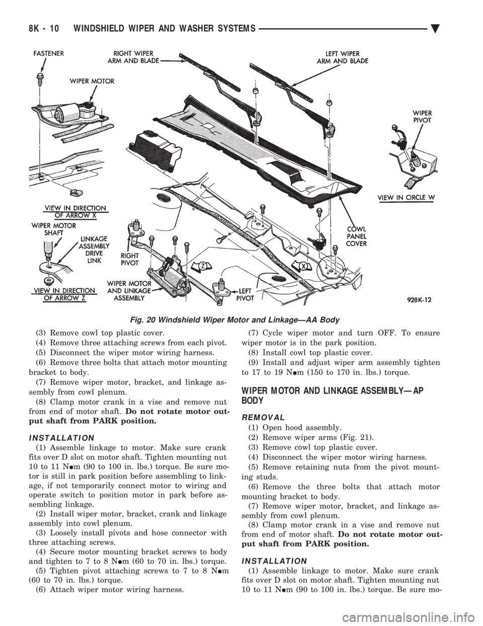
(2) Remove wiper arms (Fig. 19 and 20).
Fig. 17 Liftgate Wiper Grommet
Fig. 18 Liftgate Wiper MotorÐAG Body
8K - 8 WINDSHIELD WIPER AND WASHER SYSTEMS Ä
Page 630 of 2438
(3) Remove cowl top plastic cover.
(4) Remove three attaching screws from each pivot.
(5) Disconnect the wiper motor wiring harness.
(6) Remove three bolts that attach motor mounting
bracket to body. (7) Remove wiper motor, bracket, and linkage as-
sembly from cowl plenum. (8) Clamp motor crank in a vise and remove nut
from end of motor shaft. Do not rotate motor out-
put shaft from PARK position.
INSTALLATION
(1) Assemble linkage to motor. Make sure crank
fits over D slot on motor shaft. Tighten mounting nut
10 to 11 N Im (90 to 100 in. lbs.) torque. Be sure mo-
tor is still in park position before assembling to link-
age, if not temporarily connect motor to wiring and
operate switch to position motor in park before as-
sembling linkage. (2) Install wiper motor, bracket, crank and linkage
assembly into cowl plenum. (3) Loosely install pivots and hose connector with
three attaching screws. (4) Secure motor mounting bracket screws to body
and tighten to 7 to 8 N Im (60 to 70 in. lbs.) torque.
(5) Tighten pivot attaching screws to 7 to 8 N Im
(60 to 70 in. lbs.) torque. (6) Attach wiper motor wiring harness. (7) Cycle wiper motor and turn OFF. To ensure
wiper motor is in the park position. (8) Install cowl top plastic cover.
(9) Install and adjust wiper arm assembly tighten
to 17 to 19 N Im (150 to 170 in. lbs.) torque.
WIPER MOTOR AND LINKAGE ASSEMBLYÐAP
BODY
REMOVAL
(1) Open hood assembly.
(2) Remove wiper arms (Fig. 21).
(3) Remove cowl top plastic cover.
(4) Disconnect the wiper motor wiring harness.
(5) Remove retaining nuts from the pivot mount-
ing studs. (6) Remove the three bolts that attach motor
mounting bracket to body. (7) Remove wiper motor, bracket, and linkage as-
sembly from cowl plenum. (8) Clamp motor crank in a vise and remove nut
from end of motor shaft. Do not rotate motor out-
put shaft from PARK position.
INSTALLATION
(1) Assemble linkage to motor. Make sure crank
fits over D slot on motor shaft. Tighten mounting nut
10 to 11 N Im (90 to 100 in. lbs.) torque. Be sure mo-
Fig. 20 Windshield Wiper Motor and LinkageÐAA Body
8K - 10 WINDSHIELD WIPER AND WASHER SYSTEMS Ä
Page 649 of 2438
EXTERIOR LAMPSÐAA BODY INDEX
page page
Center High-Mounted Stop Lamp (CHMSL) Bulb . . 9
Fog Lamp ............................... 9
Fog Lamp Bulb ........................... 9
Front Side Marker Lamp or Bulb .............. 7
Headlamp Bulb ........................... 7 Headlamp Lens
........................... 7
License Plate Lamp or BulbÐAA/P Body ....... 8
License Plate LampsÐAA/C Body ............. 8
Park and Turn Signal Lamp or Bulb ........... 7
Tail, Stop and Turn Signal and Back-Up Lamp . . . 8
HEADLAMP BULB
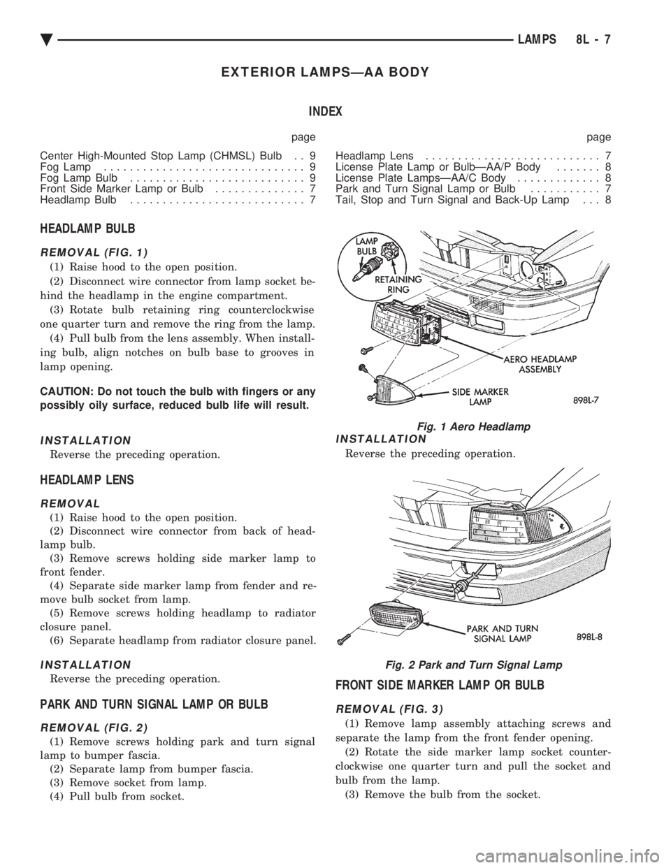
REMOVAL (FIG. 1)
(1) Raise hood to the open position.
(2) Disconnect wire connector from lamp socket be-
hind the headlamp in the engine compartment. (3) Rotate bulb retaining ring counterclockwise
one quarter turn and remove the ring from the lamp. (4) Pull bulb from the lens assembly. When install-
ing bulb, align notches on bulb base to grooves in
lamp opening.
CAUTION: Do not touch the bulb with fingers or any
possibly oily surface, reduced bulb life will result.
INSTALLATION
Reverse the preceding operation.
HEADLAMP LENS
REMOVAL
(1) Raise hood to the open position.
(2) Disconnect wire connector from back of head-
lamp bulb. (3) Remove screws holding side marker lamp to
front fender. (4) Separate side marker lamp from fender and re-
move bulb socket from lamp. (5) Remove screws holding headlamp to radiator
closure panel. (6) Separate headlamp from radiator closure panel.
INSTALLATION
Reverse the preceding operation.
PARK AND TURN SIGNAL LAMP OR BULB
REMOVAL (FIG. 2)
(1) Remove screws holding park and turn signal
lamp to bumper fascia. (2) Separate lamp from bumper fascia.
(3) Remove socket from lamp.
(4) Pull bulb from socket.
INSTALLATION
Reverse the preceding operation.
FRONT SIDE MARKER LAMP OR BULB
REMOVAL (FIG. 3)
(1) Remove lamp assembly attaching screws and
separate the lamp from the front fender opening. (2) Rotate the side marker lamp socket counter-
clockwise one quarter turn and pull the socket and
bulb from the lamp. (3) Remove the bulb from the socket.
Fig. 1 Aero Headlamp
Fig. 2 Park and Turn Signal Lamp
Ä LAMPS 8L - 7
Page 652 of 2438
EXTERIOR LAMPSÐAC BODY INDEX
page page
Aero Headlamp Bulb ...................... 10
Aero Headlamp Housing ................... 11
Aero HeadlampsÐAC/D-Body ............... 10
Center High Mounted Stop Lamp (CHMSL) ..... 13
Center High-Mounted Stop Lamp (CHMSL) Bulb . 13
Cornering Lamp Assembly .................. 12
Cornering Lamp Bulb ..................... 12
Front Side Marker BulbÐAC/C-Body .......... 12
Front Side Marker LampÐAC/C-Body ......... 12
Headlamp Diagnosis ...................... 10 Headlamp Sealed BeamÐAC/C Body
......... 10
License Plate Lamp/Bulb ................... 13
Park/Turn Signal Lamp or BulbÐAC/C-Body .... 11
Park/Turn Signal Lamp or BulbÐAC/D-Body .... 11
Rear Side Marker Lamp BulbÐAC/C-Body ..... 13
Rear Side Marker LampÐAC/C-Body ......... 13
Tail, Stop, Turn Signal, Back-Up and Side Marker LampÐAC/D-Body ...................... 12
Tail, Stop, Turn Signal, Back-Up LampÐAC/C or AY/S-Body ............................ 12
HEADLAMP DIAGNOSIS
Refer to the Headlamp Diagnosis at the beginning of
this Group. Refer to Wiring Diagrams Manual for
circuit and component locations.
HEADLAMP SEALED BEAMÐAC/C BODY
REMOVAL
(1) Turn the headlight switch ON.
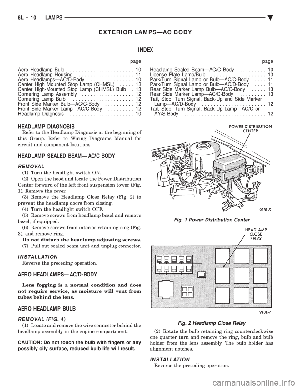
(2) Open the hood and locate the Power Distribution
Center forward of the left front suspension tower (Fig.
1). Remove the cover. (3) Remove the Headlamp Close Relay (Fig. 2) to
prevent the headlamp doors from closing. (4) Turn the headlight switch OFF.
(5) Remove screws from headlamp bezel and remove
bezel, if equipped. (6) Remove screws from interior retaining ring (Fig.
3), and remove ring. Do not disturb the headlamp adjusting screws.
(7) Pull out sealed beam unit and unplug connector.
INSTALLATION
Reverse the preceding operation.
AERO HEADLAMPSÐAC/D-BODY
Lens fogging is a normal condition and does
not require service, as moisture will vent from
tubes behind the lens.
AERO HEADLAMP BULB
REMOVAL (FIG. 4)
(1) Locate and remove the wire connector behind the
headlamp assembly in the engine compartment.
CAUTION: Do not touch the bulb with fingers or any
possibly oily surface, reduced bulb life will result. (2) Rotate the bulb retaining ring counterclockwise
one quarter turn and remove the ring, bulb and bulb
holder from the lens assembly. The bulb holder has
alignment notches.
INSTALLATION
Reverse the preceding operation.
Fig. 1 Power Distribution Center
Fig. 2 Headlamp Close Relay
8L - 10 LAMPS Ä