1993 CHEVROLET DYNASTY tow bar
[x] Cancel search: tow barPage 43 of 2438

TOWING RECOMMENDATIONS
RECOMMENDED TOWING EQUIPMENT
To avoid damage to bumper fascia and air dams
use of a wheel lift or flat bed towing device (Fig. 8) is
recommended. When using a wheel lift towing de-
vice, be sure the unlifted end of disabled vehicle has
at least 100 mm (4 in.) ground clearance. If mini-
mum ground clearance cannot be reached, use a tow-
ing dolly. If a flat bed device is used, the approach
angle should not exceed 15 degrees.
GROUND CLEARANCE
CAUTION: If vehicle is towed with wheels removed,
install lug nuts to retain brake drums or rotors.
A towed vehicle should be raised until lifted wheels
are a minimum 100 mm (4 in) from the ground. Be
sure there is adequate ground clearance at the oppo-
site end of the vehicle, especially when towing over
rough terrain or steep rises in the road. If necessary,
remove the wheels from the lifted end of the vehicle
and lower the vehicle closer to the ground, to in-
crease the ground clearance at the opposite end of
the vehicle. Install lug nuts on wheel attaching studs
to retain brake drums or rotors.
LOCKED VEHICLE TOWING
When a locked vehicle must be towed with the
front wheels on the ground, use a towing dolly or flat
bed hauler.
FLAT TOWING WITH TOW BAR
² 4-speed automatic transaxle vehicles can be flat
towed at speeds not to exceed 72 km/h (44 mph) for
not more than 160 km (100 miles). The steering col-
umn must be unlocked and gear selector in neutral.
² 3-speed automatic transaxle vehicles can be flat
towed at speeds not to exceed 40 km/h (25 mph) for
not more than 25 km (15 miles). The steering column
must be unlocked and gear selector in neutral.
² Manual transaxle vehicles can be flat towed at any
legal highway speed with no distance restrictions.
The steering column must be unlocked and gear se-
lector in neutral. WARNING: DO NOT ALLOW TOWING ATTACH-
MENT DEVICES TO CONTACT THE FUEL TANK OR
LINES, FUEL LEAK CAN RESULT. DO NOT LIFT OR TOW VEHICLE BY FRONT OR
REAR BUMPER, OR BUMPER ENERGY ABSORBER
UNITS. DO NOT VENTURE UNDER A LIFTED VEHICLE IF
NOT SUPPORTED PROPERLY ON SAFETY
STANDS. DO NOT ALLOW PASSENGERS TO RIDE IN A
TOWED VEHICLE. USE A SAFETY CHAIN THAT IS INDEPENDENT
FROM THE TOWING ATTACHMENT DEVICE.
CAUTION: Do not damage brake lines, exhaust sys-
tem, shock absorbers, sway bars, or any other un-
der vehicle components when attaching towing
device to vehicle. Remove or secure loose or protruding objects
from a damaged vehicle before towing. Refer to state and local rules and regulations be-
fore towing a vehicle. Do not allow weight of towed vehicle to bear on
lower fascia, air dams, or spoilers.
TOWINGÐFRONT WHEEL LIFT
Chrysler Corporation recommends that a vehicle be
towed with the front end lifted, whenever possible.
TOWINGÐREAR WHEEL LIFT
If a front wheel drive vehicle cannot be towed with
the front wheels lifted, the rear wheels can be lifted
provided the following guide lines are observed.
CAUTION: Do not use steering column lock to se-
cure steering wheel during towing operation.
² Unlock steering column and secure steering wheel
in straight ahead position with a clamp device de-
signed for towing.
² Verify that front drive line and steering compo-
nents are in good condition.
² 4-speed automatic transaxle vehicles can be towed
at speeds not to exceed 72 km/h (44 mph) for not
more than 160 km (100 miles). The gear selector
must be in neutral position.
² 3-speed automatic transaxle vehicles can be towed
at speeds not to exceed 40 km/h (25 mph) for not
more than 25 km (15 miles). The gear selector must
be in neutral position.
² 3-speed automatic transaxle vehicles can be towed
at speeds not to exceed 40 km/h (25 mph) for not
more than 25 km (15 miles). The gear selector must
be in neutral position.
Fig. 8 Recommended Towing Devices
Ä LUBRICATION AND MAINTENANCE 0 - 7
Page 60 of 2438
FRONT SUSPENSION
FRONT SUSPENSION MAJOR COMPONENTS (FIG. 2)
STRUT SUPPORT
The system is supported by coil springs positioned
offset around the struts. The springs are contained
between an upper seat, located just below the top
strut mount assembly (Fig. 2) and a lower spring
seat on the strut lower housing. The top of each strut assembly is bolted to the up-
per fender reinforcement (shock tower) through a
rubber isolated mount. The bottom attaches to the top of the steering
knuckle with two through bolts. On some vehicles,
one bolt has an eccentric cam located below the head
of the bolt for camber adjustment. On the other ve-
hicles the camber adjustment is done by manually
moving the steering knuckle within the strut assem-
bly. Caster is a fixed setting on all vehicles and is
not adjustable.
STEERING KNUCKLE
The steering knuckle is a single casting with legs
machined for attachment to the strut damper, steer-
ing linkage, brake adaptor, and lower control arm
ball joint. The knuckle also holds the front drive hub
bearing. The hub is positioned through the bearing
and knuckle, with the constant velocity stub shaft
splined through the hub.
LOWER CONTROL ARM
The lower control arm is a steel casting with 2
large spool type rubber pivot bushings. The lower
control arm is bolted to the crossmember with pivot
bolts through the center of the rubber pivot bush-
ings. The ball joint is pressed into the control arm and
has a non-tapered stud with a notch for clamp bolt
clearance. The stud is clamped and locked into the
steering knuckle leg with a clamp bolt. The lower control arms are inter-connected through
a rubber isolated sway bar (Fig. 2).
DRIVESHAFTS
A left and right driveshaft is attached inboard to
the transaxle differential side gears, and outboard to
the driven wheel hub. To deliver driving force from the transaxle to the
front wheels during turning maneuvers and suspen-
sion movement. Both shafts are constructed with con-
stant velocity universal joints at both ends. Both shafts have a Tripod (sliding) joint at the
transaxle end and Rzeppa joints (with splined stub
shafts) on the hub ends. Due to the transaxle loca-
tion the connecting shafts between the C/V joints are
of different length and construction. The right shaft
is longer and of tubular construction. The left shaft
is solid.
2 - 2 SUSPENSION AND DRIVESHAFTS Ä
Page 72 of 2438
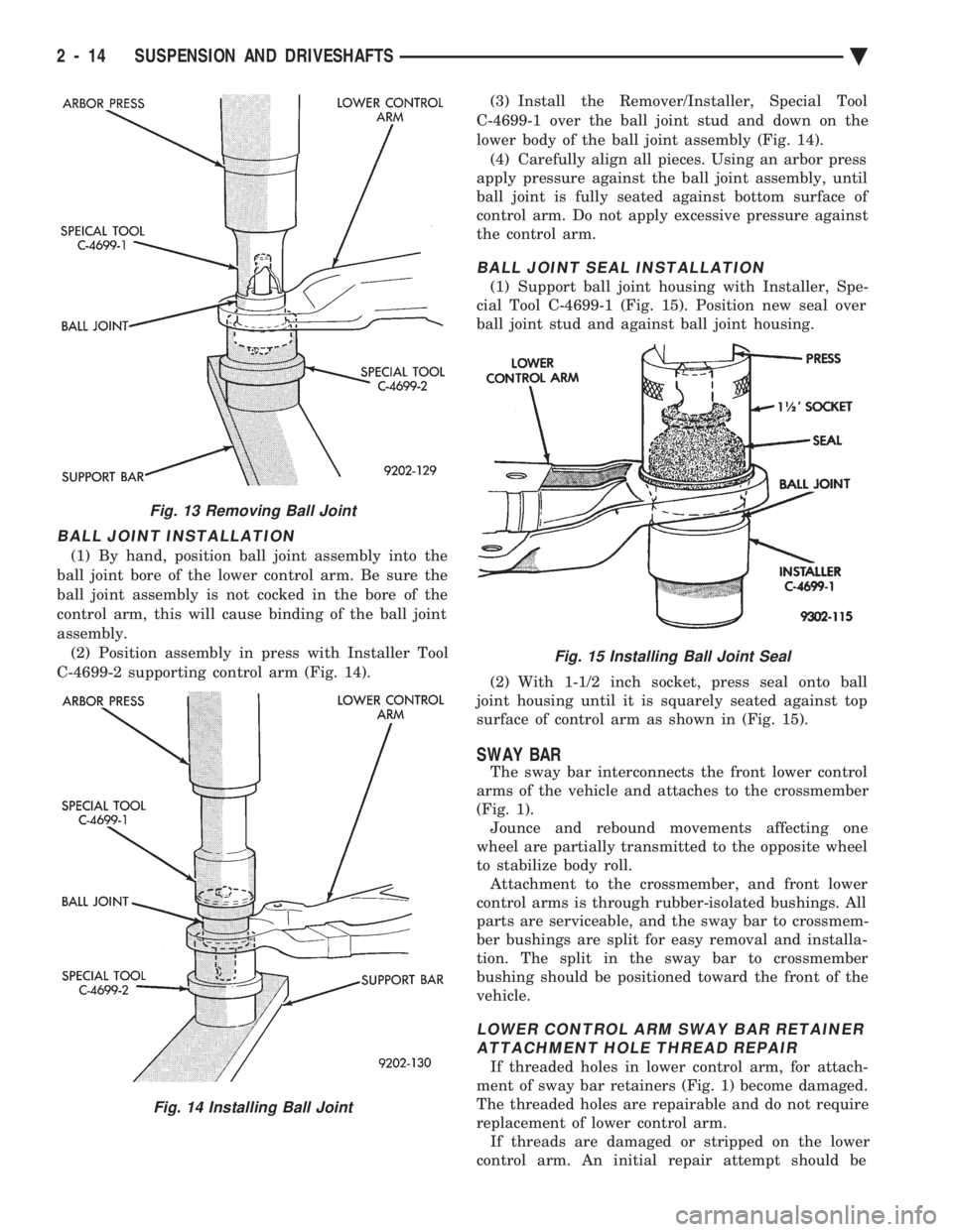
BALL JOINT INSTALLATION
(1) By hand, position ball joint assembly into the
ball joint bore of the lower control arm. Be sure the
ball joint assembly is not cocked in the bore of the
control arm, this will cause binding of the ball joint
assembly. (2) Position assembly in press with Installer Tool
C-4699-2 supporting control arm (Fig. 14). (3) Install the Remover/Installer, Special Tool
C-4699-1 over the ball joint stud and down on the
lower body of the ball joint assembly (Fig. 14). (4) Carefully align all pieces. Using an arbor press
apply pressure against the ball joint assembly, until
ball joint is fully seated against bottom surface of
control arm. Do not apply excessive pressure against
the control arm.
BALL JOINT SEAL INSTALLATION
(1) Support ball joint housing with Installer, Spe-
cial Tool C-4699-1 (Fig. 15). Position new seal over
ball joint stud and against ball joint housing.
(2) With 1-1/2 inch socket, press seal onto ball
joint housing until it is squarely seated against top
surface of control arm as shown in (Fig. 15).
SWAY BAR
The sway bar interconnects the front lower control
arms of the vehicle and attaches to the crossmember
(Fig. 1). Jounce and rebound movements affecting one
wheel are partially transmitted to the opposite wheel
to stabilize body roll. Attachment to the crossmember, and front lower
control arms is through rubber-isolated bushings. All
parts are serviceable, and the sway bar to crossmem-
ber bushings are split for easy removal and installa-
tion. The split in the sway bar to crossmember
bushing should be positioned toward the front of the
vehicle.
LOWER CONTROL ARM SWAY BAR RETAINER ATTACHMENT HOLE THREAD REPAIR
If threaded holes in lower control arm, for attach-
ment of sway bar retainers (Fig. 1) become damaged.
The threaded holes are repairable and do not require
replacement of lower control arm. If threads are damaged or stripped on the lower
control arm. An initial repair attempt should be
Fig. 13 Removing Ball Joint
Fig. 14 Installing Ball Joint
Fig. 15 Installing Ball Joint Seal
2 - 14 SUSPENSION AND DRIVESHAFTS Ä
Page 73 of 2438
made by using a (M10 x 1.5 - 6H) thread chasing tap
on the holes to restore the threads to a usable condi-
tion. If threads can be restored to a usable condition,
install sway bar retainer attaching bolts and torque
to 68 N Im (50 ft. lbs.).
CAUTION: When performing repair procedure listed
below. Be sure replacement bolts and nuts meet the
same requirements as the original equipment man-
ufactures specifications.
If damage to threaded holes in lower control arm,
can not be restored to a usable condition using the
above procedure. Drill out holes in lower control arm
using an 11 mm drill bit. Then use a bolt and nut for
attachment of sway bar retainer to lower control
arm. Torque the nut and bolt to 68 N Im (50 ft. lbs.).
REMOVAL
(1) Raise and support the vehicle. See Hoisting in
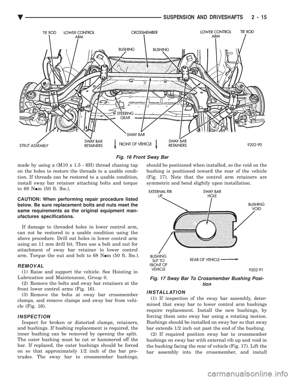
Lubrication and Maintenance, Group 0. (2) Remove the bolts and sway bar retainers at the
front lower control arms (Fig. 16). (3) Remove the bolts at sway bar crossmember
clamps, and remove clamps and sway bar from vehi-
cle (Fig. 16).
INSPECTION
Inspect for broken or distorted clamps, retainers,
and bushings. If bushing replacement is required, the
inner bushing can be removed by opening the split.
The outer bushing must be cut or hammered off the
bar. If replaced, the outer bushings should be forced
on so that approximately 1/2 inch of the bar pro-
trudes. The sway bar to crossmember bushings, should be positioned when installed, so the void on the
bushing is positioned toward the rear of the vehicle
(Fig. 17). Note that the control arm retainers are
symmetric and bend slightly upon installation.
INSTALLATION
(1) If inspection of the sway bar assembly, deter-
mined that sway bar to lower control arm bushings
require replacement. Install the new bushings, by
forcing them onto sway bar using a rotating motion.
Bushings should be installed on sway bar so that sway
bar extends 1/2 inch out past the end of the bushing. (2) If required position sway bar to crossmember
bushings on sway bar with external rib up and void in
the bushing facing the rear of vehicle (Fig. 17). Lift the
bar assembly into the crossmember, and install
Fig. 16 Front Sway Bar
Fig. 17 Sway Bar To Crossmember Bushing Posi- tion
Ä SUSPENSION AND DRIVESHAFTS 2 - 15
Page 74 of 2438
the lower clamps and bolts. The center offset in the
sway bar should be oriented toward the front of the
vehicle (Fig. 16)(3) Position bushing retainers on lower control arms
and install bolts (Fig. 16). (4) With lower control arms raised to design height,
tighten all retainer attaching bolts to 70 N Im (50 ft.
lbs.) torque. (5) Lower vehicle.
KNUCKLE (FRONT SUSPENSION)
The front suspension knuckle (Fig. 1) provides for
steering control of the vehicle. Supports the brake
caliper and absorbs the loads exerted during vehicle
braking. It also supports the front (driving) hub and
bearing and stub axle assembly. The front suspension knuckle also provides the abil-
ity to align the front wheels of the vehicle. This is done
by allowing for front wheel camber adjustment and the
ability for front tire Toe adjustments The front suspension knuckle is not a serviceable
component. Do not attempt to straighten or repair the
front suspension knuckle in any way. Service repair or replacement of the front (drive) hub
and bearing, can be done with the front suspension
knuckle remaining on the vehicle.
REMOVAL
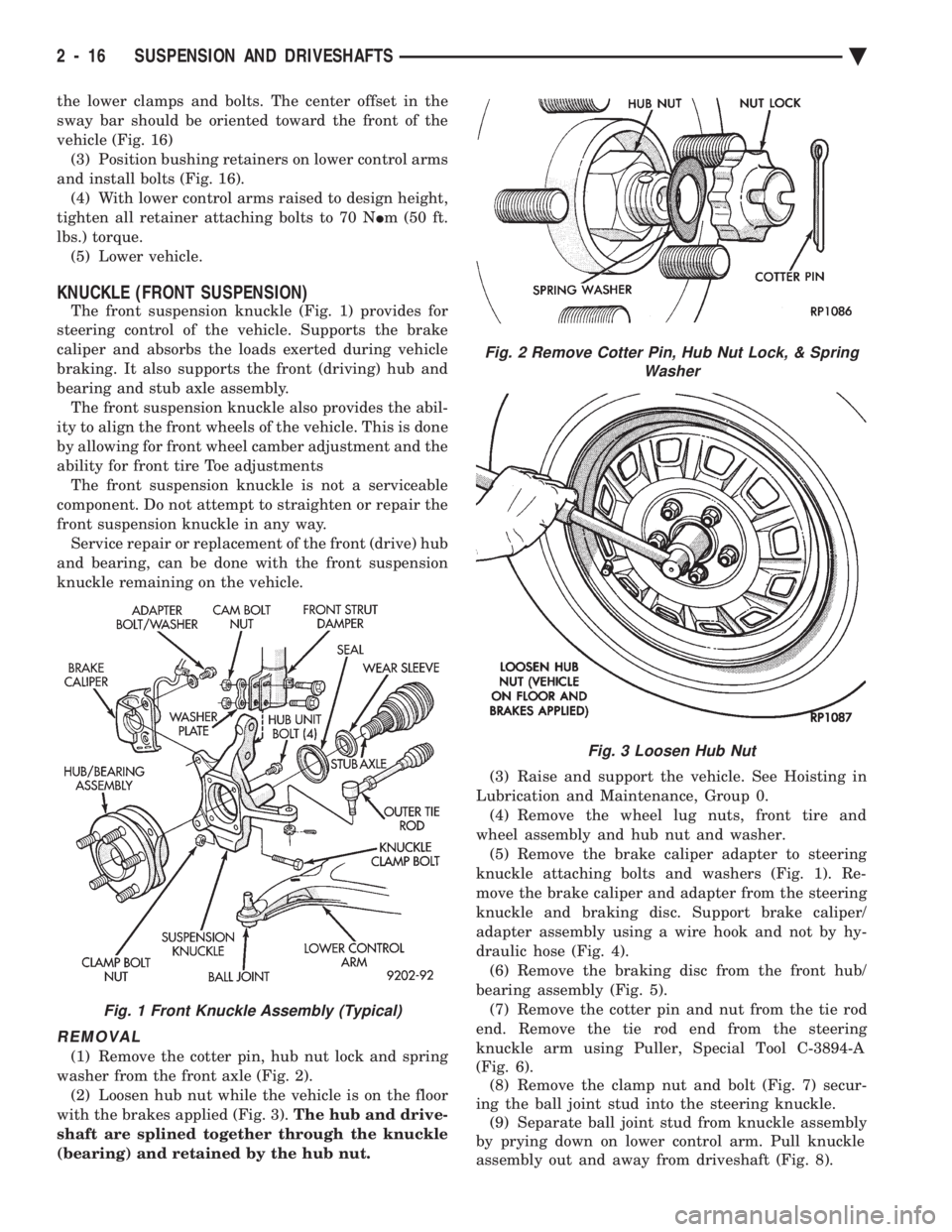
(1) Remove the cotter pin, hub nut lock and spring
washer from the front axle (Fig. 2). (2) Loosen hub nut while the vehicle is on the floor
with the brakes applied (Fig. 3). The hub and drive-
shaft are splined together through the knuckle
(bearing) and retained by the hub nut. (3) Raise and support the vehicle. See Hoisting in
Lubrication and Maintenance, Group 0. (4) Remove the wheel lug nuts, front tire and
wheel assembly and hub nut and washer. (5) Remove the brake caliper adapter to steering
knuckle attaching bolts and washers (Fig. 1). Re-
move the brake caliper and adapter from the steering
knuckle and braking disc. Support brake caliper/
adapter assembly using a wire hook and not by hy-
draulic hose (Fig. 4). (6) Remove the braking disc from the front hub/
bearing assembly (Fig. 5). (7) Remove the cotter pin and nut from the tie rod
end. Remove the tie rod end from the steering
knuckle arm using Puller, Special Tool C-3894-A
(Fig. 6). (8) Remove the clamp nut and bolt (Fig. 7) secur-
ing the ball joint stud into the steering knuckle. (9) Separate ball joint stud from knuckle assembly
by prying down on lower control arm. Pull knuckle
assembly out and away from driveshaft (Fig. 8).
Fig. 2 Remove Cotter Pin, Hub Nut Lock, & Spring Washer
Fig. 3 Loosen Hub Nut
Fig. 1 Front Knuckle Assembly (Typical)
2 - 16 SUSPENSION AND DRIVESHAFTS Ä
Page 163 of 2438
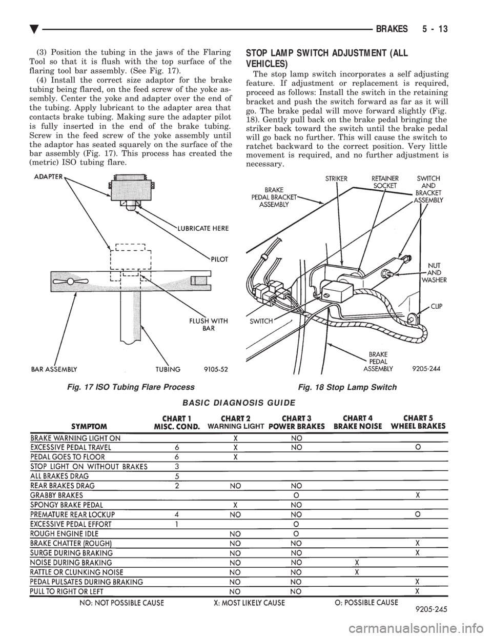
(3) Position the tubing in the jaws of the Flaring
Tool so that it is flush with the top surface of the
flaring tool bar assembly. (See Fig. 17). (4) Install the correct size adaptor for the brake
tubing being flared, on the feed screw of the yoke as-
sembly. Center the yoke and adapter over the end of
the tubing. Apply lubricant to the adapter area that
contacts brake tubing. Making sure the adapter pilot
is fully inserted in the end of the brake tubing.
Screw in the feed screw of the yoke assembly until
the adaptor has seated squarely on the surface of the
bar assembly (Fig. 17). This process has created the
(metric) ISO tubing flare.STOP LAMP SWITCH ADJUSTMENT (ALL
VEHICLES)
The stop lamp switch incorporates a self adjusting
feature. If adjustment or replacement is required,
proceed as follows: Install the switch in the retaining
bracket and push the switch forward as far as it will
go. The brake pedal will move forward slightly (Fig.
18). Gently pull back on the brake pedal bringing the
striker back toward the switch until the brake pedal
will go back no further. This will cause the switch to
ratchet backward to the correct position. Very little
movement is required, and no further adjustment is
necessary.
Fig. 17 ISO Tubing Flare ProcessFig. 18 Stop Lamp Switch
BASIC DIAGNOSIS GUIDE
Ä BRAKES 5 - 13
Page 436 of 2438

OVERHEAD CONSOLE REPLACEMENT
(1) Unscrew the mounting screw in sun glass bin
compartment (Fig. 8).
(2) Slide console forward toward windshield until
the console unhooks from roof bracket. (3) Disconnect wire harness from console.
(4) For installation reverse above procedures.
COMPASS MODULE REPLACEMENT
(1) Remove overhead console.
(2) Using a small screwdriver, release the 2 snaps
at rear of compass module (Fig. 9).
(3) After releasing the 2 snaps, slide compass mod-
ule rearward until free of mounting bar. (4) For installation reverse above procedures.
ELECTRONIC VEHICLE INFORMATION CENTER
(EVIC) REMOVAL
(1) Use a straight edge tool to pry out one end of
the EVIC center and continue to disengage six clips
along the length of the message center. (2) Remove the EVIC center and disconnect the
wiring. (3) For installation reverse the above procedures.
AMBIENT TEMPERATURE SENSOR REMOVAL
(1) Raise and support vehicle on safety stands.
(2) From behind front bumper fascia, remove screw
attaching sensor to radiator closure panel (Fig. 10).
(3) For installation, reverse above procedures.
ENGINE NODE SENSOR REMOVAL
(1) Raise and support vehicle on safety stands.
(2) From behind front bumper fascia, remove
screws attaching engine node to bumper fascia (Fig.
11). (3) For installation, reverse above procedures.
Fig. 8 Overhead Console Mounting
Fig. 9 Compass Module Removal
Fig. 10 Ambient Temperature Sensor
Fig. 11 Engine Node
8C - 20 OVERHEAD CONSOLE Ä
Page 441 of 2438

Test 3 (d3) performs a walking segment test which,
sequentially puts different directions and numbers on
the display. If any segment fails, replace the compass
module.
OVERHEAD CONSOLE REPLACEMENT
(1) Unscrew the mounting screw in sun glass bin
compartment (Fig. 6).
(2) Slide console forward toward windshield until
the console unhooks from roof bracket. (3) Disconnect wire harness from console.
(4) For installation reverse above procedures.
COMPASS MODULE REPLACEMENT
(1) Remove overhead console (Fig 6).
(2) Using a small screwdriver, release the 2 snaps
at rear of compass module (Fig. 7). (3) After releasing the 2 snaps, slide compass mod-
ule rearward until free of mounting bar. (4) For installation reverse above procedures.
AMBIENT TEMPERATURE SENSOR REMOVAL
(1) Raise and support vehicle on safety stands.
(2) Behind front bumper fascia, remove screw at-
taching sensor to radiator closure panel (Fig. 8). (3) For installation, reverse above procedures.
Fig. 6 Overhead Console Mounting
Fig. 7 Compass Module Removal
Fig. 8 Ambient Temperature Sensor
Ä
OVERHEAD CONSOLE 8C - 25