1993 CHEVROLET DYNASTY load capacity
[x] Cancel search: load capacityPage 102 of 2438

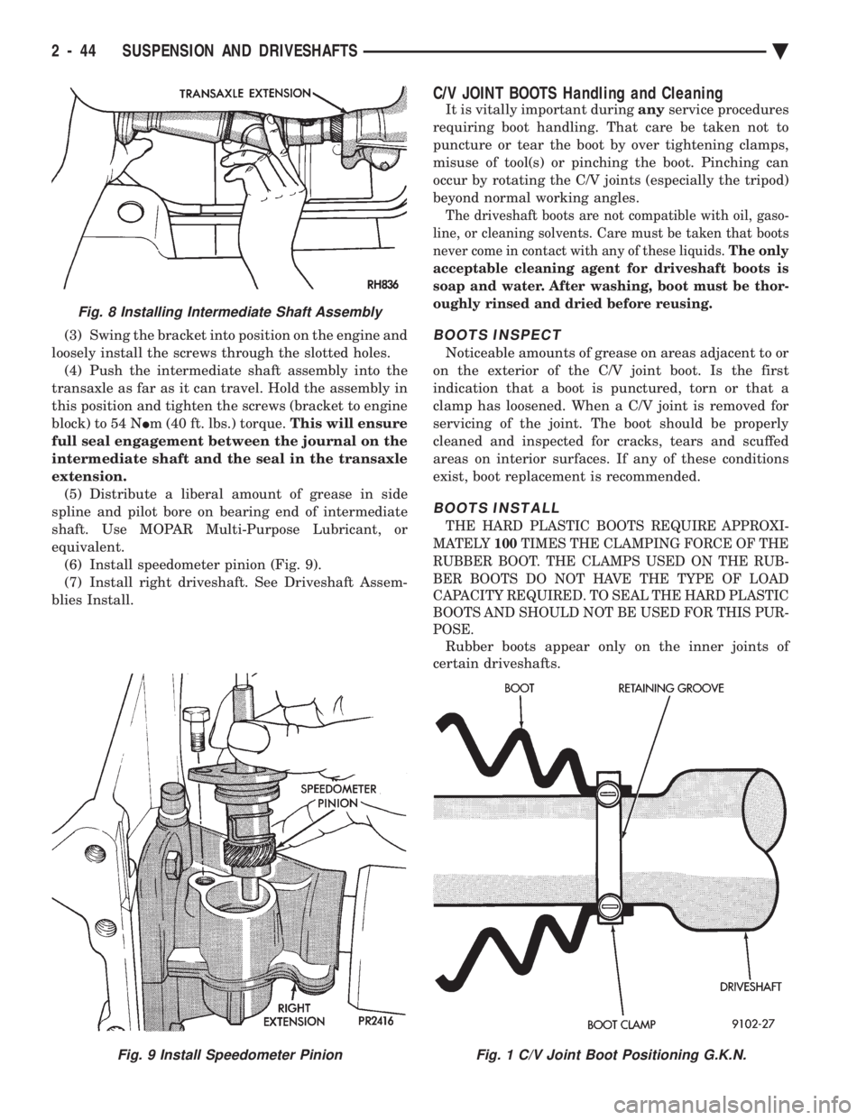
(3) Swing the bracket into position on the engine and
loosely install the screws through the slotted holes. (4) Push the intermediate shaft assembly into the
transaxle as far as it can travel. Hold the assembly in
this position and tighten the screws (bracket to engine
block) to 54 N Im (40 ft. lbs.) torque. This will ensure
full seal engagement between the journal on the
intermediate shaft and the seal in the transaxle
extension. (5) Distribute a liberal amount of grease in side
spline and pilot bore on bearing end of intermediate
shaft. Use MOPAR Multi-Purpose Lubricant, or
equivalent. (6) Install speedometer pinion (Fig. 9).
(7) Install right driveshaft. See Driveshaft Assem-
blies Install.
C/V JOINT BOOTS Handling and Cleaning
It is vitally important during anyservice procedures
requiring boot handling. That care be taken not to
puncture or tear the boot by over tightening clamps,
misuse of tool(s) or pinching the boot. Pinching can
occur by rotating the C/V joints (especially the tripod)
beyond normal working angles.
The driveshaft boots are not compatible with oil, gaso-
line, or cleaning solvents. Care must be taken that boots
never come in contact with any of these liquids. The only
acceptable cleaning agent for driveshaft boots is
soap and water. After washing, boot must be thor-
oughly rinsed and dried before reusing.
BOOTS INSPECT
Noticeable amounts of grease on areas adjacent to or
on the exterior of the C/V joint boot. Is the first
indication that a boot is punctured, torn or that a
clamp has loosened. When a C/V joint is removed for
servicing of the joint. The boot should be properly
cleaned and inspected for cracks, tears and scuffed
areas on interior surfaces. If any of these conditions
exist, boot replacement is recommended.
BOOTS INSTALL
THE HARD PLASTIC BOOTS REQUIRE APPROXI-
MATELY 100TIMES THE CLAMPING FORCE OF THE
RUBBER BOOT. THE CLAMPS USED ON THE RUB-
BER BOOTS DO NOT HAVE THE TYPE OF LOAD
CAPACITY REQUIRED. TO SEAL THE HARD PLASTIC
BOOTS AND SHOULD NOT BE USED FOR THIS PUR-
POSE.
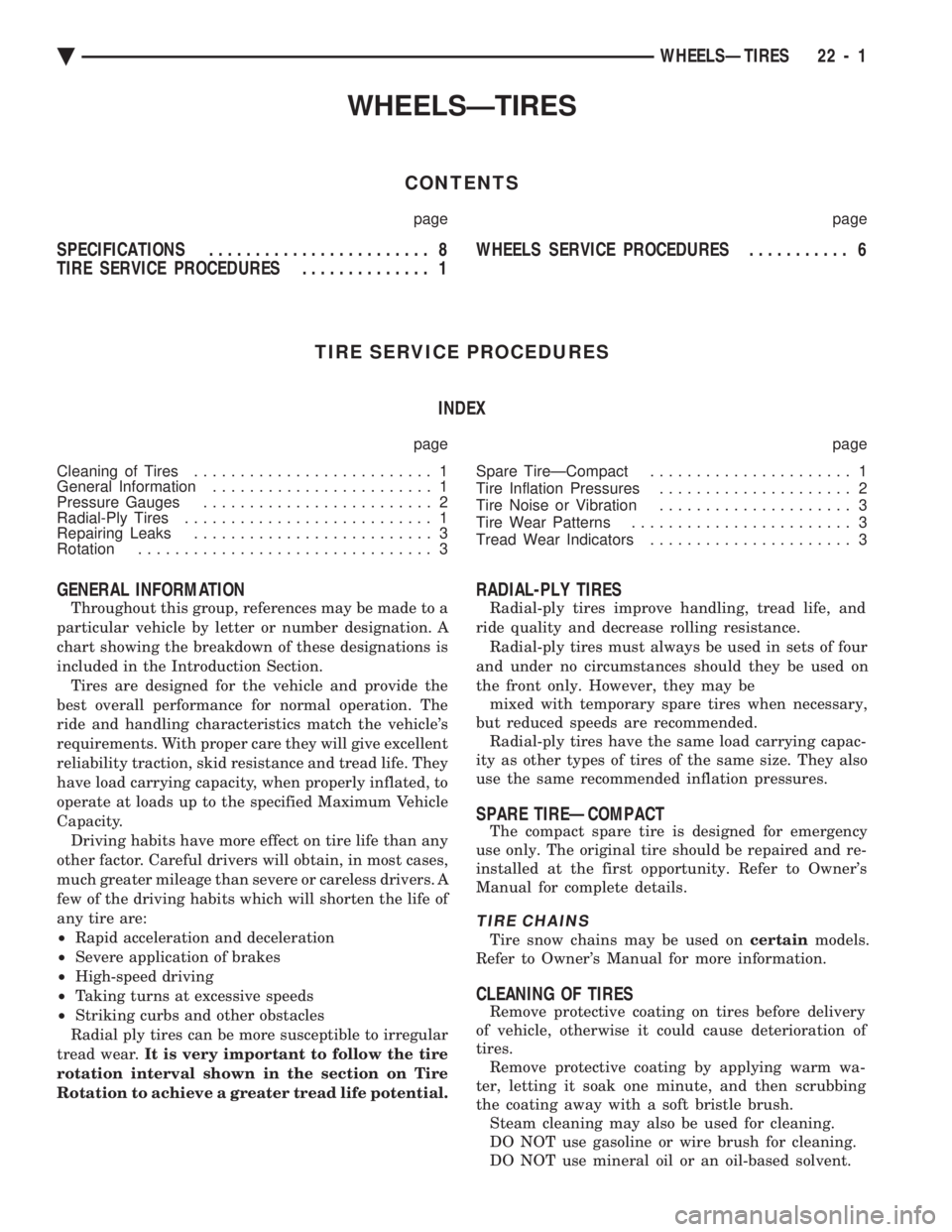
Rubber boots appear only on the inner joints of
certain driveshafts.
Fig. 9 Install Speedometer PinionFig. 1 C/V Joint Boot Positioning G.K.N.
Fig. 8 Installing Intermediate Shaft Assembly
2 - 44 SUSPENSION AND DRIVESHAFTS Ä
Page 376 of 2438

It is important when using the Test Indicator that
the battery be level and have a clean top to see the
correct indications. A light may be required to view
the Indicator.
WARNING: DO NOT USE OPEN FLAME NEAR BAT-
TERY BECAUSE OF EXPLOSIVE GASES AT FORM
ABOVE BATTERY.
STATE OF CHARGE TESTS
USING TEST INDICATOR
The built in test hydrometer (Figs. 3, 4 and 5) mea-
sures the specific gravity of the electrolyte. Specific
Gravity (SG) of the electrolyte will show state of
charge voltage. The test indicator WILL NOT show
cranking capacity of the battery. Refer to Battery
Load. Look into the sight glass (Figs. 4 and 5) and
note the color of the indicator (Fig. 5). Refer to the
following description of colors:
² GREEN = 75 to 100 degree state of charge
The battery is adequately charged for further test-
ing and may be returned to use. If the vehicle will
not crank for a maximum 15 seconds, refer to Bat-
tery Load Test in this Group for more information.
² BLACK OR DAR K=0to75degree state of
charge The battery is INADEQUATELY charged and
must be charged until green dot is visible, (12.4 volts
or greater) before the battery is tested or returned to
use. Refer to Causes of Battery Discharging.
² YELLOW OR BRIGHT COLOR = Battery must
be replace
WARNING: DO NOT CHARGE, ASSIST BOOST,
LOAD TEST, OR ADD WATER TO THE BATTERY
WHEN YELLOW OR BRIGHT COLOR DOT IS VISI-
BLE. PERSONAL INJURY MAY OCCUR.
A yellow or bright color dot shows electrolyte level
in battery is below the test indicator (Fig. 5). Water
cannot be added to a maintenance free battery. The
battery must be replaced. A low electrolyte level may
be caused by an over charging condition. Refer to
Generator Test Procedures on Vehicle.
CAUSES OF BATTERY DISCHARGING
It is normal to have a small 5 to 30 milliamperes
continuous electrical draw from the battery. This
draw will take place with the ignition in the OFF po-
sition, and the courtesy, dome, storage compart-
ments, and engine compartment lights OFF. The
continuous draw is due to various electronic features
or accessories that require electrical current with the
ignition OFF to function properly. When a vehicle is
not used over an extended period approximately 20
days the Main Fusible Link Connector (Fig. 6)
should be disconnected. This is located near the bat- tery on the engine wiring harness. Disconnection of
this connector will help prevent battery discharging.
Refer to Fig. 7 for Battery Diagnostics.
ABNORMAL BATTERY DISCHARGING
(1) Corroded battery posts, cables or terminals.
(2) Loose or worn generator drive belt.
(3) Electrical loads that exceed the output of the
charging system due to equipment or accessories in-
stalled after delivery. (4) Slow driving speeds in heavy traffic conditions
or prolonged idling with high-amperage electrical
systems in use. (5) Defective electrical circuit or component caus-
ing excess Ignition Off Draw (IOD). Refer to Ignition
OFF Draw (IOD). (6) Defective charging system.
(7) Defective battery.
BATTERY OPEN CIRCUIT VOLTAGE TEST
An open circuit voltage, no load test will show the
state of charge in a battery. Also, if it will pass a
load test of 50 percent of the battery cold crank rat-
ing. Refer to Battery Load Test. If a battery has an
open circuit voltage reading of 12.4 volts or greater,
and will not pass a load test, it is defective and re-
placement would be required. To test open circuit
voltage, perform the following operation: (1) Remove both battery cables, negative first. If
the battery has been boosted, charged, or loaded just
prior to this operation, allow the battery a few min-
utes to stabilize. (2) Using a voltmeter connected to the battery
posts and measure the open circuit voltage (Fig. 8).
Fig. 6 Main Fusible Link Connector
8A - 4 BATTERY/STARTING/CHARGING SYSTEMS DIAGNOSTICS Ä
Page 378 of 2438

This voltage reading will show the battery state of
charge. It will not reveal battery cranking capacity
(Fig. 8).
BATTERY LOAD TEST
A fully charged battery must have reserve crank-
ing capacity. This will enable the starter motor and
ignition system enough power to start the engine
over a broad range of ambient temperatures. A bat-
tery load test will verify the actual cranking perfor-
mance based on the cold crank rating of the battery.
WARNING: IF BATTERY SHOWS SIGNS OF FREEZ-
ING, LEAKING, LOOSE POSTS, OR EXCESSIVELY
LOW ELECTROLYTE LEVEL, DO NOT TEST. ACID
BURNS OR AN EXPLOSIVE CONDITION MAY RE-
SULT. (1) Remove both battery cables, negative first. Bat-
tery top, cables and posts should be clean. If green
dot is not visible in indicator, charge the battery. Re-
fer to Battery Charging Procedures. (2) Use a suitable Volt Ammeter Load tester (Fig.
10) connected to the battery posts (Fig. 11). Check
the open circuit voltage of the battery. Voltage should be equal to or greater than 12.4
volts with the green dot visible in test indicator. (3) Rotate the load control knob Carbon pile rheo-
stat to apply a 300 amp load. Apply this load for 15 seconds to remove the surface charge from the bat-
tery, and return the control knob to off (Fig. 12).
(4) Allow the battery to stabilize for 15 seconds,
and then verify open circuit voltage. (5) Rotate the load control knob on the tester to
maintain 50 percent of the battery cold crank rating
for a minimum 15 seconds (Fig. 13).
Fig. 8 Testing Open Circuit Voltage
Fig. 9 Battery Open Circuit Voltage
Fig. 10 Volt-Ammeter-Load Tester
Fig. 11 Volt-Ammeter-Load Tester Connections
Fig. 12 Remove Surface Charge from Battery
8A - 6 BATTERY/STARTING/CHARGING SYSTEMS DIAGNOSTICS Ä
Page 380 of 2438

ity. Refer to Battery Load Test. If the battery will
endure a load test, return the battery to use. If bat-
tery will not endure a load test, it must be replaced.
Properly clean and inspect battery hold downs, tray,
terminals, cables, posts, and top before completing
service. Also refer to Group 8B, Battery/Starter/Gen-
erator Service.
CHARGING TIME REQUIRED
The time required to charge a battery will vary de-
pending upon the following factors:
² SIZE OF BATTERY
A completely discharged large heavy-duty battery
requires more than twice the recharging time as a
completely discharged small capacity battery (Fig.
16).
² TEMPERATURE: A longer time will be needed to
charge a battery at -18ÉC (0ÉF) than at 27ÉC (80ÉF).
When a fast charger is connected to a cold battery,
current accepted by battery will be very low at first.
In time, the battery will accept a higher rate as bat-
tery warms.
² CHARGER CAPACITY: A charger which, can sup-
ply only five amperes will require a much longer pe-
riod of charging than a charger that can supply 30
amperes or more.
² STATE OF CHARGE: A completely discharged
battery requires more charging time than a partially
charged battery. Electrolyte is nearly pure water in a
completely discharged battery. At first, the charging
current amperage will be low. As water is converted
to sulfuric acid inside the battery, the current amp
rate will rise. Also, the specific gravity of the electro-
lyte will rise, bringing the green dot (Fig. 5) into
view.
WARNING: NEVER EXCEED 20 AMPS WHEN
CHARGING A COLD -1ÉC (30ÉF) BATTERY. PER-
SONAL INJURY MAY RESULT.
CHARGING COMPLETELY DISCHARGED BATTERY
The following procedure should be used to recharge
a completely discharged battery. Unless procedure is
properly followed, a good battery may be needlessly
replaced (Fig. 17).
(1) Measure the voltage at battery posts with a
voltmeter accurate to 1/10 volt (Fig. 18). If below 10
volts, charge current will be low, and it could take
some time before it accepts a current in excess of a
few milliamperes. Such low current may not be de-
tectable on amp meters built into many chargers.
(2) Connect charger leads. Some chargers feature
polarity protection circuitry which, prevents opera-
tion unless charger is connected to battery posts cor-
rectly. A completely discharged battery may not have
enough voltage to activate this circuitry. This may
happen even if the leads are connected properly. (3) Battery chargers vary in the amount of voltage
and current they provide. For the time required for
the battery to accept measurable charger current at
various voltages, refer to Fig. 17. If charge current is
still not measurable after charging period the battery
should be replaced. If charge current is measurable
during charging time, the battery may be good, and
charging should be completed in the normal manner.
Fig. 16 Battery Charging Time
Fig. 17 Charge Rate
Fig. 18 Voltmeter Accurate to 1/10 Volt (Connected)
8A - 8 BATTERY/STARTING/CHARGING SYSTEMS DIAGNOSTICS Ä
Page 2149 of 2438

WHEELSÐTIRES
CONTENTS
page page
SPECIFICATIONS ........................ 8
TIRE SERVICE PROCEDURES .............. 1 WHEELS SERVICE PROCEDURES
........... 6
TIRE SERVICE PROCEDURES INDEX
page page
Cleaning of Tires .......................... 1
General Information ........................ 1
Pressure Gauges ......................... 2
Radial-Ply Tires ........................... 1
Repairing Leaks .......................... 3
Rotation ................................ 3 Spare TireÐCompact
...................... 1
Tire Inflation Pressures ..................... 2
Tire Noise or Vibration ..................... 3
Tire Wear Patterns ........................ 3
Tread Wear Indicators ...................... 3
GENERAL INFORMATION
Throughout this group, references may be made to a
particular vehicle by letter or number designation. A
chart showing the breakdown of these designations is
included in the Introduction Section. Tires are designed for the vehicle and provide the
best overall performance for normal operation. The
ride and handling characteristics match the vehicle's
requirements. With proper care they will give excellent
reliability traction, skid resistance and tread life. They
have load carrying capacity, when properly inflated, to
operate at loads up to the specified Maximum Vehicle
Capacity. Driving habits have more effect on tire life than any
other factor. Careful drivers will obtain, in most cases,
much greater mileage than severe or careless drivers. A
few of the driving habits which will shorten the life of
any tire are:
² Rapid acceleration and deceleration
² Severe application of brakes
² High-speed driving
² Taking turns at excessive speeds
² Striking curbs and other obstacles
Radial ply tires can be more susceptible to irregular
tread wear. It is very important to follow the tire
rotation interval shown in the section on Tire
Rotation to achieve a greater tread life potential.
RADIAL-PLY TIRES
Radial-ply tires improve handling, tread life, and
ride quality and decrease rolling resistance. Radial-ply tires must always be used in sets of four
and under no circumstances should they be used on
the front only. However, they may be mixed with temporary spare tires when necessary,
but reduced speeds are recommended. Radial-ply tires have the same load carrying capac-
ity as other types of tires of the same size. They also
use the same recommended inflation pressures.
SPARE TIREÐCOMPACT
The compact spare tire is designed for emergency
use only. The original tire should be repaired and re-
installed at the first opportunity. Refer to Owner's
Manual for complete details.
TIRE CHAINS
Tire snow chains may be used on certainmodels.
Refer to Owner's Manual for more information.
CLEANING OF TIRES
Remove protective coating on tires before delivery
of vehicle, otherwise it could cause deterioration of
tires. Remove protective coating by applying warm wa-
ter, letting it soak one minute, and then scrubbing
the coating away with a soft bristle brush. Steam cleaning may also be used for cleaning.
DO NOT use gasoline or wire brush for cleaning.
DO NOT use mineral oil or an oil-based solvent.
Ä WHEELSÐTIRES 22 - 1
Page 2150 of 2438

PRESSURE GAUGES
High quality dial type air pressure gauges are rec-
ommended. After checking pressure with the gauge,
replace valve caps and tighten finger tight.
TIRE INFLATION PRESSURES
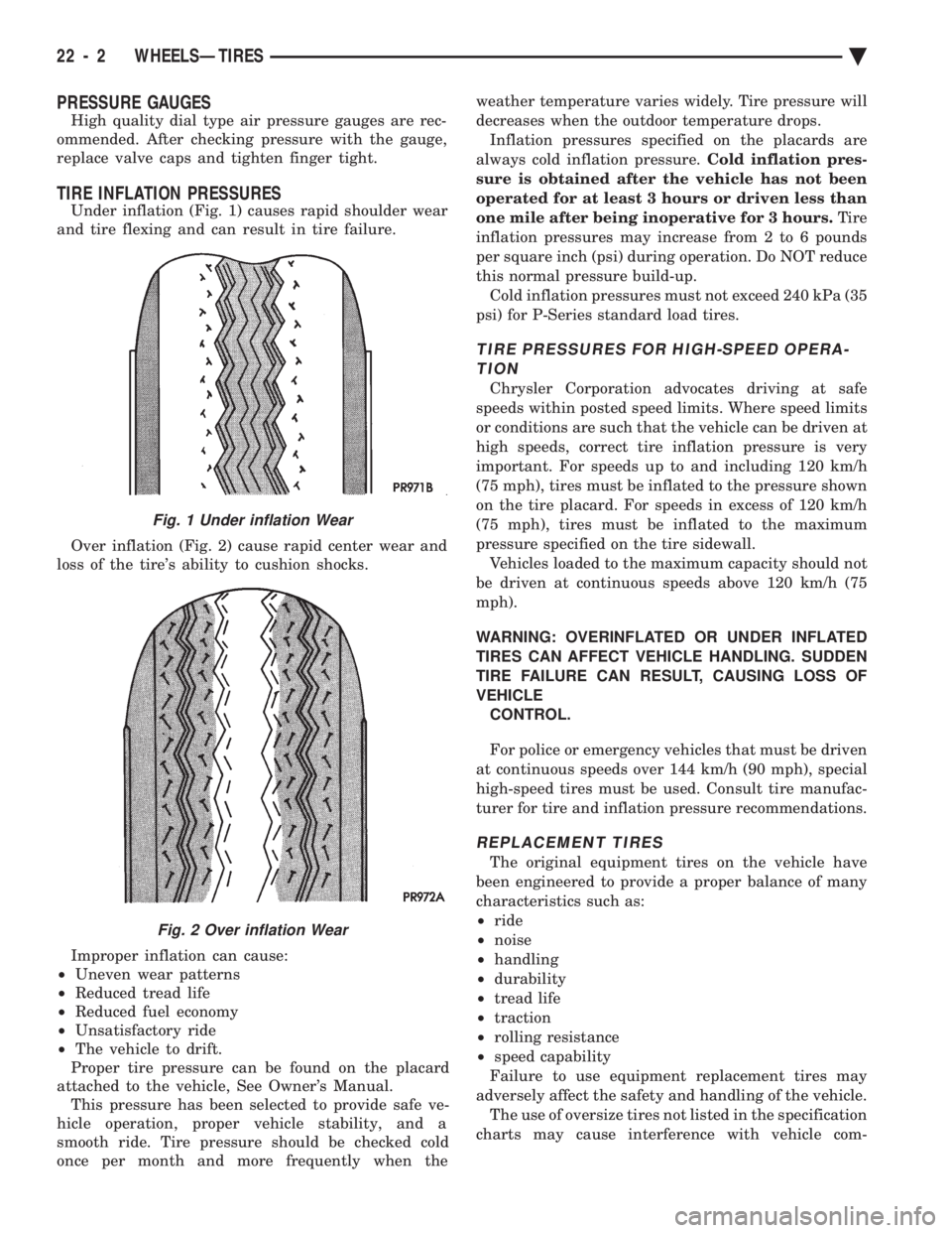
Under inflation (Fig. 1) causes rapid shoulder wear
and tire flexing and can result in tire failure.
Over inflation (Fig. 2) cause rapid center wear and
loss of the tire's ability to cushion shocks.
Improper inflation can cause:
² Uneven wear patterns
² Reduced tread life
² Reduced fuel economy
² Unsatisfactory ride
² The vehicle to drift.
Proper tire pressure can be found on the placard
attached to the vehicle, See Owner's Manual. This pressure has been selected to provide safe ve-
hicle operation, proper vehicle stability, and a
smooth ride. Tire pressure should be checked cold
once per month and more frequently when the weather temperature varies widely. Tire pressure will
decreases when the outdoor temperature drops.
Inflation pressures specified on the placards are
always cold inflation pressure. Cold inflation pres-
sure is obtained after the vehicle has not been
operated for at least 3 hours or driven less than
one mile after being inoperative for 3 hours. Tire
inflation pressures may increase from 2 to 6 pounds
per square inch (psi) during operation. Do NOT reduce
this normal pressure build-up. Cold inflation pressures must not exceed 240 kPa (35
psi) for P-Series standard load tires.
TIRE PRESSURES FOR HIGH-SPEED OPERA- TION
Chrysler Corporation advocates driving at safe
speeds within posted speed limits. Where speed limits
or conditions are such that the vehicle can be driven at
high speeds, correct tire inflation pressure is very
important. For speeds up to and including 120 km/h
(75 mph), tires must be inflated to the pressure shown
on the tire placard. For speeds in excess of 120 km/h
(75 mph), tires must be inflated to the maximum
pressure specified on the tire sidewall. Vehicles loaded to the maximum capacity should not
be driven at continuous speeds above 120 km/h (75
mph).
WARNING: OVERINFLATED OR UNDER INFLATED
TIRES CAN AFFECT VEHICLE HANDLING. SUDDEN
TIRE FAILURE CAN RESULT, CAUSING LOSS OF
VEHICLE CONTROL.
For police or emergency vehicles that must be driven
at continuous speeds over 144 km/h (90 mph), special
high-speed tires must be used. Consult tire manufac-
turer for tire and inflation pressure recommendations.
REPLACEMENT TIRES
The original equipment tires on the vehicle have
been engineered to provide a proper balance of many
characteristics such as:
² ride
² noise
² handling
² durability
² tread life
² traction
² rolling resistance
² speed capability
Failure to use equipment replacement tires may
adversely affect the safety and handling of the vehicle. The use of oversize tires not listed in the specification
charts may cause interference with vehicle com-
Fig. 1 Under inflation Wear
Fig. 2 Over inflation Wear
22 - 2 WHEELSÐTIRES Ä
Page 2154 of 2438

WHEELS SERVICE PROCEDURES INDEX
page page
General Information ........................ 6
Tire and Wheel Balance .................... 6
Tire and Wheel Run Out .................... 7 Wheel Installation
......................... 6
Wheel Replacement ....................... 6
GENERAL INFORMATION
Original equipment wheels are designed for proper
operation at all loads up to the maximum vehicle ca-
pacity. All models use steel or cast aluminum drop center
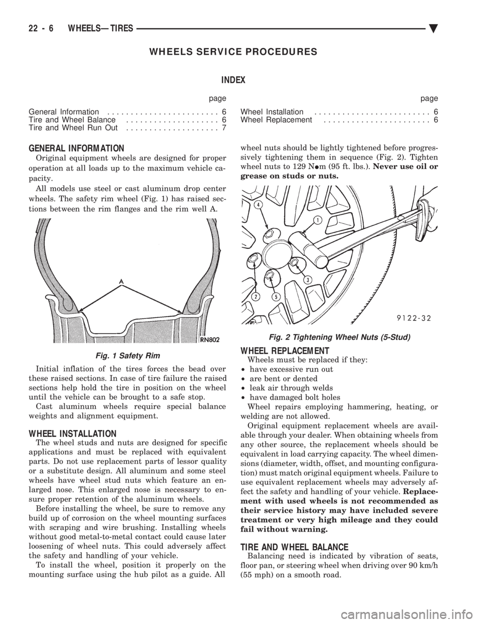
wheels. The safety rim wheel (Fig. 1) has raised sec-
tions between the rim flanges and the rim well A.
Initial inflation of the tires forces the bead over
these raised sections. In case of tire failure the raised
sections help hold the tire in position on the wheel
until the vehicle can be brought to a safe stop. Cast aluminum wheels require special balance
weights and alignment equipment.
WHEEL INSTALLATION
The wheel studs and nuts are designed for specific
applications and must be replaced with equivalent
parts. Do not use replacement parts of lessor quality
or a substitute design. All aluminum and some steel
wheels have wheel stud nuts which feature an en-
larged nose. This enlarged nose is necessary to en-
sure proper retention of the aluminum wheels. Before installing the wheel, be sure to remove any
build up of corrosion on the wheel mounting surfaces
with scraping and wire brushing. Installing wheels
without good metal-to-metal contact could cause later
loosening of wheel nuts. This could adversely affect
the safety and handling of your vehicle. To install the wheel, position it properly on the
mounting surface using the hub pilot as a guide. All wheel nuts should be lightly tightened before progres-
sively tightening them in sequence (Fig. 2). Tighten
wheel nuts to 129 N Im (95 ft. lbs.). Never use oil or
grease on studs or nuts.
WHEEL REPLACEMENT
Wheels must be replaced if they:
² have excessive run out
² are bent or dented
² leak air through welds
² have damaged bolt holes
Wheel repairs employing hammering, heating, or
welding are not allowed. Original equipment replacement wheels are avail-
able through your dealer. When obtaining wheels from
any other source, the replacement wheels should be
equivalent in load carrying capacity. The wheel dimen-
sions (diameter, width, offset, and mounting configura-
tion) must match original equipment wheels. Failure to
use equivalent replacement wheels may adversely af-
fect the safety and handling of your vehicle. Replace-
ment with used wheels is not recommended as
their service history may have included severe
treatment or very high mileage and they could
fail without warning.
TIRE AND WHEEL BALANCE
Balancing need is indicated by vibration of seats,
floor pan, or steering wheel when driving over 90 km/h
(55 mph) on a smooth road.
Fig. 1 Safety Rim
Fig. 2 Tightening Wheel Nuts (5-Stud)
22 - 6 WHEELSÐTIRES Ä