1993 CHEVROLET DYNASTY battery location
[x] Cancel search: battery locationPage 44 of 2438

ENGINE INDEX
page page
Engine Oil Filter .......................... 9
Battery ................................ 15
Crankcase Ventilation System ............... 13
Drive Belts ............................. 14
Emission Control System ................... 14
Engine Air Cleaner ....................... 11
Engine Cooling System .................... 10 Engine Oil
............................... 8
Frequency of Engine Oil and Filter Changes ..... 8
Fuel Filter .............................. 14
Fuel Recommendations .................... 14
Ignition Cables, Distributor Cap, and Rotor ..... 14
Rubber and Plastic Component Inspection ...... 15
Spark Plugs ............................ 14
FREQUENCY OF ENGINE OIL AND FILTER
CHANGES
ENGINE OIL
Road conditions as well as your kind of driving af-
fect the interval at which your oil should be changed.
Check the following to determine if any apply to you:
² Frequent short trip driving less than 8 kilometers
(5 miles)
² Frequent driving in dusty conditions
² Frequent trailer towing
² Extensive idling (such as vehicle operation in stop
and go traffic)
² More than 50% of your driving is at sustained
high speeds during hot weather, above 32ÉC (90ÉF) If any of these apply to you then change your en-
gine oil every 4 800 kilometers (3,000 miles) or 3
months, whichever comes first. If none of these apply to you then change your oil
every 12 000 kilometers (7,500 miles) or 6 months,
whichever comes first. If none of these apply and the vehicle is in com-
mercial type service such as, Police, Taxi or Limou-
sine and principally used for highway driving of 40
kilometers (25 miles) or more between stations, the
engine oil should be changed every 8 000 kilometers
(5,000 miles) or 6 months, whichever comes first.
FLEXIBLE FUEL VEHICLES
Flexible fuel is corrosive and contributes to engine
oil contamination. When flexible fuel is being used,
the engine oil should be changed every 8 000 kilome-
ters (5,000 miles) or 6 months, whichever comes first.
OIL FILTER
The engine oil filter should be replaced with a new
filter at every second oil change.
ENGINE OIL
WARNING: NEW OR USED ENGINE OIL CAN BE IR-
RITATING TO THE SKIN. AVOID PROLONGED OR
REPEATED SKIN CONTACT WITH ENGINE OIL.
CONTAMINANTS IN USED ENGINE OIL, CAUSED
BY INTERNAL COMBUSTION, CAN BE HAZARDOUS TO YOUR HEALTH. THOROUGHLY WASH EX-
POSED SKIN WITH SOAP AND WATER. DO NOT WASH SKIN WITH GASOLINE, DIESEL
FUEL, THINNER, OR SOLVENTS, HEALTH PROB-
LEMS CAN RESULT. DO NOT POLLUTE, DISPOSE OF USED ENGINE
OIL PROPERLY. CONTACT YOUR DEALER OR
GOVERNMENT AGENCY FOR LOCATION OF COL-
LECTION CENTER IN YOUR AREA.
BREAK-IN PERIOD
CAUTION: Wide open throttle operation in low
gears, before engine break-in period is complete,
can damage engine.
On a Chrysler Corporation vehicle an extended
break-in period is not required. Driving speeds of not
over 80-90 km/h (50-55 mph) for the first 100 km (60
miles) is recommended. Hard acceleration and high
engine rpm in lower gears should be avoided.
SELECTING ENGINE OIL
CAUTION: Do not use non-detergent or straight
mineral oil when adding or changing crankcase lu-
bricant. Engine or Turbocharger failure can result.
The factory fill engine oil is a high quality, energy
conserving, crankcase lubricant. The Recommended
SAE Viscosity Grades chart defines the viscosity
grades that must be used based on temperature in
the region where vehicle is operated and optional
equipment.
NON-FLEXIBLE FUEL VEHICLES Chrysler Corporation recommends that Mopar mo-
tor oil, or equivalent, be used when adding or chang-
ing crankcase lubricant. The API symbol (Fig. 1) on
the container indicates the viscosity grade, quality
and fuel economy ratings of the lubricant it contains.
Use ENERGY CONSERVING II motor oil with API
SERVICE SG or SG/CD classification.
0 - 8 LUBRICATION AND MAINTENANCE Ä
Page 144 of 2438
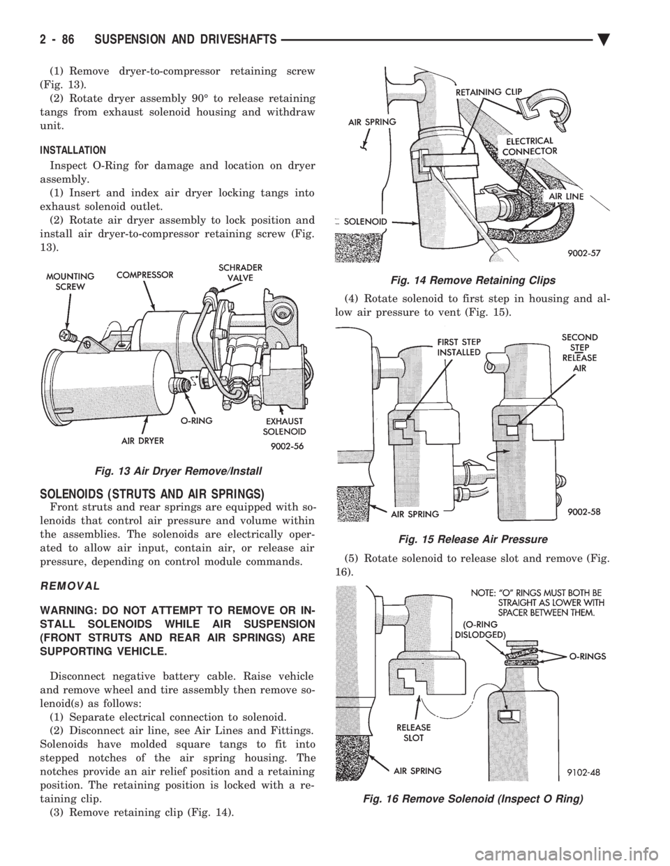
(1) Remove dryer-to-compressor retaining screw
(Fig. 13). (2) Rotate dryer assembly 90É to release retaining
tangs from exhaust solenoid housing and withdraw
unit.
INSTALLATION
Inspect O-Ring for damage and location on dryer
assembly. (1) Insert and index air dryer locking tangs into
exhaust solenoid outlet. (2) Rotate air dryer assembly to lock position and
install air dryer-to-compressor retaining screw (Fig.
13).
SOLENOIDS (STRUTS AND AIR SPRINGS)
Front struts and rear springs are equipped with so-
lenoids that control air pressure and volume within
the assemblies. The solenoids are electrically oper-
ated to allow air input, contain air, or release air
pressure, depending on control module commands.
REMOVAL
WARNING: DO NOT ATTEMPT TO REMOVE OR IN-
STALL SOLENOIDS WHILE AIR SUSPENSION
(FRONT STRUTS AND REAR AIR SPRINGS) ARE
SUPPORTING VEHICLE.
Disconnect negative battery cable. Raise vehicle
and remove wheel and tire assembly then remove so-
lenoid(s) as follows: (1) Separate electrical connection to solenoid.
(2) Disconnect air line, see Air Lines and Fittings.
Solenoids have molded square tangs to fit into
stepped notches of the air spring housing. The
notches provide an air relief position and a retaining
position. The retaining position is locked with a re-
taining clip. (3) Remove retaining clip (Fig. 14). (4) Rotate solenoid to first step in housing and al-
low air pressure to vent (Fig. 15).
(5) Rotate solenoid to release slot and remove (Fig.
16).
Fig. 13 Air Dryer Remove/Install
Fig. 14 Remove Retaining Clips
Fig. 15 Release Air Pressure
Fig. 16 Remove Solenoid (Inspect O Ring)
2 - 86 SUSPENSION AND DRIVESHAFTS Ä
Page 266 of 2438
If the vehicle is not set in motion within 3 minutes
from the time the ignition switch is set in the on po-
sition. The solenoid test is bypassed but the pump/
motor is activated briefly to verify that it is
operating correctly.
WARNING SYSTEMS OPERATION
The ABS system uses an Amber Anti-Lock Warn-
ing Lamp, located in the instrument cluster. The
purpose of the warning lamp is discussed in detail
below. The Amber Anti-Lock Warning Light will turn on
when the (CAB) detects a condition which results in
a shutdown of the Anti-Lock function. The Amber
Anti-Lock Warning Lamp is normally on until the
(CAB) completes its self tests and turns the lamp off
(approximately 1-2 seconds). When the Amber Anti-
Lock Warning Light is on only the Anti-Lock func-
tion of the brake system if affected. The standard
brake system and the ability to stop the car will not
be affected when only the Amber Anti-Lock Warning
Light is on.
NORMAL OPERATION OF WARNING LAMP
With the ignition in the Crank position, the Red
Brake Warning Lamp will turn on as a bulb check.
The Amber Anti-Lock Warning Lamp will stay on for
1-2 seconds then turn off. Once verification of the self
diagnosis is completed.
ANTI-LOCK BRAKE SYSTEM COMPONENTS
The following is a detailed description of the Anti-
Lock Brake System components. For information on
servicing the Four Wheel Disk Brake System, see the
standard Brake section of this Service Manual.
MODULATOR ASSEMBLY
WARNING: THE ONLY PART OF THE MODULATOR
ASSEMBLY THAT IS A SERVICEABLE COMPONENT
IS THE DELTA P SWITCH. THE REMAINING COM-
PONENTS OF THE MODULATOR ASSEMBLY ARE
NOT SERVICEABLE ITEMS. NO ATTEMPT SHOULD
BE MADE TO REMOVE OR SERVICE ANY OTHER
PARTS OF THE MODULATOR ASSEMBLY.
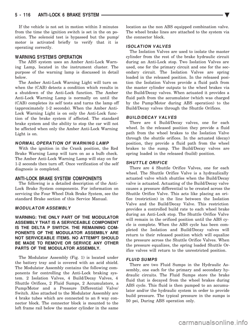
The Modulator Assembly (Fig. 1) is located under
the battery tray and is covered with an acid shield.
The Modulator Assembly contains the following com-
ponents for controlling the Anti-Lock braking sys-
tem. 2 Isolation Valves, 4 Build/Decay Valves, 4
Shuttle Orifices, 2 Fluid Sumps, 2 Accumulators, a
Pump/Motor and a Pressure Differential Valve/
Switch. Also attached to the Modulator Assembly are
4 brake tubes which are connected to an 8 way con-
nector block. The connector block is mounted to the
left frame rail below the master cylinder in the same location as the non ABS equipped combination valve.
The wheel brake lines are attached to the system via
the connector block.
ISOLATION VALVES
The Isolation Valves are used to isolate the master
cylinder from the rest of the brake hydraulic circuit
during an Anti-Lock stop. Two Isolation Valves are
used, one for the primary circuit and one for the sec-
ondary circuit. The Isolation Valves are spring
loaded in the released position. In the released posi-
tion the Isolation Valves provide a fluid path from
the master cylinder outputs to the wheel brakes via
the Build/Decay valves. When actuated it provides a
fluid path from the accumulator (which was charged
by the Pump/Motor during ABS operation) to the
Build/Decay valves through the Shuttle Orifices.
BUILD/DECAY VALVES
There are 4 Build/Decay valves, one for each
wheel. In the released position they provide a fluid
path from the wheel brakes to the Isolation Valve
through the shuttle orifices. In the actuated (decay)
position, they provide a fluid path from the wheel
brakes to the sump. The Build/Decay valves are
spring loaded in the released (build) position.
SHUTTLE ORIFICE
There are 4 Shuttle Orifice Valves, one for each
wheel. The Shuttle Orifice Valve is a hydraulically
actuated valve which shuttles when the Build/Decay
valve is actuated. Actuating of the Build/Decay valve
causes a pressure differential to be created across the
Shuttle Orifice Valve. This acts like placing an ori-
fice (restriction) in the line between the Isolation
Valve and the Build/Decay Valve. This restriction
provides a controlled build rate to each wheel brake
during an Anti-Lock stop. The Shuttle Orifice Valve
will remain in the orificed position until the ABS cy-
cle is complete. When the ABS cycle has been com-
pleted the Isolation and Build/Decay valves will
return to their released position which will equalize
the pressure across the Shuttle Orifice Valves. When
the pressure equalizes, the spring loaded Shuttle Or-
ifice valves will return to the unrestricted position.
FLUID SUMPS
There are two Fluid Sumps in the Hydraulic As-
sembly, one each for the primary and secondary hy-
draulic circuits. The Fluid Sumps store the brake
fluid that is decayed from the wheel brakes during
ABS cycle. This fluid is then pumped to an accumu-
lator and/or the hydraulic system in order to provide
build pressure. The typical pressure in the sumps is
50 psi, During ABS operation only.
5 - 116 ANTI-LOCK 6 BRAKE SYSTEM Ä
Page 302 of 2438

(2) The voltage output from each of the wheel
speed sensors is verified to be within the correct op-
erating range. If a vehicle is not set in motion within 3 minutes
from the time the ignition switch is turned to the on
position. The solenoid valve test is bypassed but the
pump/motor is activated briefly to verify that it is op-
erating correctly.
WARNING SYSTEMS OPERATION
The ABS system uses an Amber Antilock Warning
Lamp, located in the instrument cluster. The purpose
of the warning lamp is discussed in detail below. The Amber Antilock Warning Light will turn on
whenever the CAB detects a condition which results
in a shutdown of the Antilock brake system. The
Amber Antilock Warning Lamp is normally on until
the CAB completes its self tests and turns the lamp
off (approximately 1-2 seconds). When the Amber
Antilock Warning Light is on, only the Antilock
brake function of the brake system if affected. The
standard brake system and the ability to stop the car
will not be affected when only the Amber Antilock
Warning Light is on.
NORMAL OPERATION OF WARNING LAMP
With ignition key turned to the Crank position, the
Red Brake Warning Lamp and Amber Antilock
Warning Lamp will turn on as a bulb check. The
Amber Antilock Warning Lamp will stay on for 1-2
seconds then turn off, once verification of Antilock
Brake System self diagnosis is completed.
ANTILOCK BRAKE SYSTEM COMPONENTS
The following is a detailed description of the Ben-
dix Antilock 4 Brake System components. For infor-
mation on servicing the Four Wheel Disc Brake
System, see the standard Brake section in the Front
Wheel Drive Car, chassis service manual.
MODULATOR ASSEMBLY
WARNING: THE ONLY COMPONENTS OF THE
MODULATOR ASSSEMBLY THAT ARE SERVICE-
ABLE, ARE THE 2 PROPORTIONING VALVES,
BLEED SCREWS AND THREAD SAVERS. THE RE-
MAINING COMPONENTS OF THE MODULATOR AS-
SEMBLY ARE NOT INTENDED TO BE
SERVICEABLE ITEMS. NO ATTEMPT SHOULD BE
MADE TO REMOVE OR SERVICE ANY OTHER COM-
PONENTS OF THE MODEULATOR ASSEMBLY.
The Modulator Assembly (Fig. 1) is located under
the battery tray and is covered with an acid shield.
The Modulator Assembly contains the following com-
ponents for controlling the Antilock brake system. 4
Build/Decay Valves, 4 Shuttle Orifices, 2 Fluid
Sumps, 2 Accumulators, and a Pump/Motor assem- bly. Also attached to the Modulator Assembly are 6
brake tubes which are connected to a 12 way junc-
tion block. The junction block (Fig. 2) is mounted to
the left frame rail below the master cylinder in the
same location as the non ABS equipped combination
valve. The wheel brake lines are attached to the sys-
tem via the connector block.BUILD/DECAY VALVES
There are 4 Build/Decay valves, one for each
wheel. In the released position they provide a fluid
path direct to the wheel brakes. In the actuated (de-
cay) position, they provide a fluid path from the
wheel brakes to the sump. The Build/Decay valves
are spring loaded in the released (build) position.
SHUTTLE ORIFICE
There are 4 Shuttle Orifice Valves, one for each
wheel. The Shuttle Orifice Valve is a hydraulically
actuated valve which shuttles when the Build/Decay
valve is actuated. Actuating of the Build/Decay valve
causes a pressure differential to be created across the
Shuttle Orifice Valve. This acts like placing an ori-
Fig. 1 Modulator Assembly
Fig. 2 Antilock Brake Junction Block
5 - 16 ANTILOCK 4 BRAKE SYSTEM Ä
Page 316 of 2438
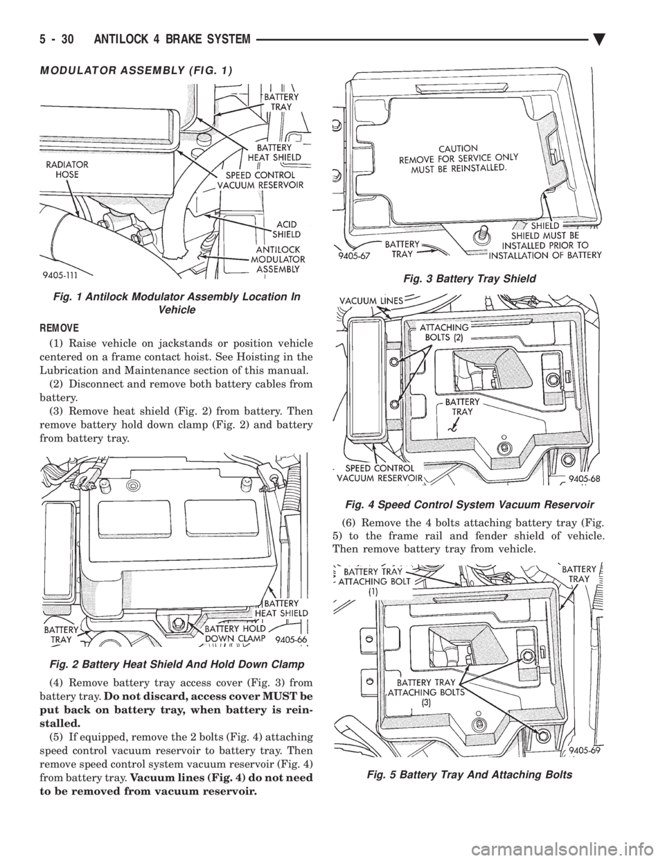
MODULATOR ASSEMBLY (FIG. 1)
REMOVE (1) Raise vehicle on jackstands or position vehicle
centered on a frame contact hoist. See Hoisting in the
Lubrication and Maintenance section of this manual. (2) Disconnect and remove both battery cables from
battery. (3) Remove heat shield (Fig. 2) from battery. Then
remove battery hold down clamp (Fig. 2) and battery
from battery tray.
(4) Remove battery tray access cover (Fig. 3) from
battery tray. Do not discard, access cover MUST be
put back on battery tray, when battery is rein-
stalled. (5) If equipped, remove the 2 bolts (Fig. 4) attaching
speed control vacuum reservoir to battery tray. Then
remove speed control system vacuum reservoir (Fig. 4)
from battery tray. Vacuum lines (Fig. 4) do not need
to be removed from vacuum reservoir. (6) Remove the 4 bolts attaching battery tray (Fig.
5) to the frame rail and fender shield of vehicle.
Then remove battery tray from vehicle.
Fig. 3 Battery Tray Shield
Fig. 4 Speed Control System Vacuum Reservoir
Fig. 5 Battery Tray And Attaching Bolts
Fig. 1 Antilock Modulator Assembly Location In Vehicle
Fig. 2 Battery Heat Shield And Hold Down Clamp
5 - 30 ANTILOCK 4 BRAKE SYSTEM Ä
Page 322 of 2438
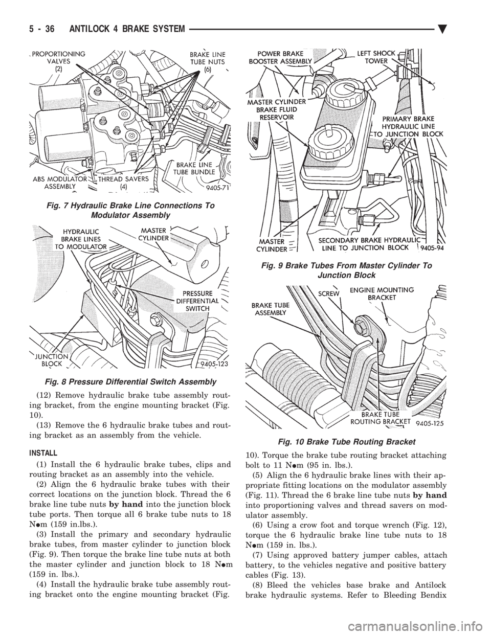
(12) Remove hydraulic brake tube assembly rout-
ing bracket, from the engine mounting bracket (Fig.
10). (13) Remove the 6 hydraulic brake tubes and rout-
ing bracket as an assembly from the vehicle.
INSTALL (1) Install the 6 hydraulic brake tubes, clips and
routing bracket as an assembly into the vehicle. (2) Align the 6 hydraulic brake tubes with their
correct locations on the junction block. Thread the 6
brake line tube nuts by handinto the junction block
tube ports. Then torque all 6 brake tube nuts to 18
N Im (159 in.lbs.).
(3) Install the primary and secondary hydraulic
brake tubes, from master cylinder to junction block
(Fig. 9). Then torque the brake line tube nuts at both
the master cylinder and junction block to 18 N Im
(159 in. lbs.). (4) Install the hydraulic brake tube assembly rout-
ing bracket onto the engine mounting bracket (Fig. 10). Torque the brake tube routing bracket attaching
bolt to 11 N
Im (95 in. lbs.).
(5) Align the 6 hydraulic brake lines with their ap-
propriate fitting locations on the modulator assembly
(Fig. 11). Thread the 6 brake line tube nuts by hand
into proportioning valves and thread savers on mod-
ulator assembly. (6) Using a crow foot and torque wrench (Fig. 12),
torque the 6 hydraulic brake line tube nuts to 18
N Im (159 in. lbs.).
(7) Using approved battery jumper cables, attach
battery, to the vehicles negative and positive battery
cables (Fig. 13). (8) Bleed the vehicles base brake and Antilock
brake hydraulic systems. Refer to Bleeding Bendix
Fig. 7 Hydraulic Brake Line Connections To Modulator Assembly
Fig. 8 Pressure Differential Switch Assembly
Fig. 9 Brake Tubes From Master Cylinder To Junction Block
Fig. 10 Brake Tube Routing Bracket
5 - 36 ANTILOCK 4 BRAKE SYSTEM Ä
Page 327 of 2438
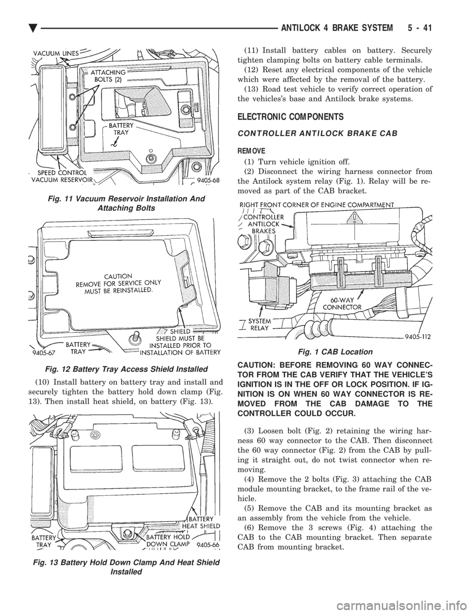
(10) Install battery on battery tray and install and
securely tighten the battery hold down clamp (Fig.
13). Then install heat shield, on battery (Fig. 13). (11) Install battery cables on battery. Securely
tighten clamping bolts on battery cable terminals. (12) Reset any electrical components of the vehicle
which were affected by the removal of the battery. (13) Road test vehicle to verify correct operation of
the vehicles's base and Antilock brake systems.
ELECTRONIC COMPONENTS
CONTROLLER ANTILOCK BRAKE CAB
REMOVE
(1) Turn vehicle ignition off.
(2) Disconnect the wiring harness connector from
the Antilock system relay (Fig. 1). Relay will be re-
moved as part of the CAB bracket.
CAUTION: BEFORE REMOVING 60 WAY CONNEC-
TOR FROM THE CAB VERIFY THAT THE VEHICLE'S
IGNITION IS IN THE OFF OR LOCK POSITION. IF IG-
NITION IS ON WHEN 60 WAY CONNECTOR IS RE-
MOVED FROM THE CAB DAMAGE TO THE
CONTROLLER COULD OCCUR.
(3) Loosen bolt (Fig. 2) retaining the wiring har-
ness 60 way connector to the CAB. Then disconnect
the 60 way connector (Fig. 2) from the CAB by pull-
ing it straight out, do not twist connector when re-
moving. (4) Remove the 2 bolts (Fig. 3) attaching the CAB
module mounting bracket, to the frame rail of the ve-
hicle. (5) Remove the CAB and its mounting bracket as
an assembly from the vehicle from the vehicle. (6) Remove the 3 screws (Fig. 4) attaching the
CAB to the CAB mounting bracket. Then separate
CAB from mounting bracket.
Fig. 11 Vacuum Reservoir Installation And Attaching Bolts
Fig. 12 Battery Tray Access Shield Installed
Fig. 13 Battery Hold Down Clamp And Heat Shield Installed
Fig. 1 CAB Location
Ä ANTILOCK 4 BRAKE SYSTEM 5 - 41
Page 387 of 2438

STARTER CONTROL CIRCUIT TESTS
The starter control circuit has:
² Starter solenoid
² Starter relay (Fig. 2)
² Neutral starting and back-up switch with auto-
matic transmissions
² Clutch pedal mounted starter interlock switch
with manual transmissions
² Ignition switch
² Battery
² All related wiring and connections
CAUTION: Before performing any starter tests, the
ignition system must be disabled.
² VEHICLES EQUIPPED WITH A CONVEN-
TIONAL DISTRIBUTOR: Disconnect coil wire from
distributor cap center tower. Secure wire to a good
ground to prevent engine from starting (Fig. 6).
² VEHICLES EQUIPPED WITH DIRECT IGNI-
TION SYSTEM: Unplug the coils electrical connector
(Fig. 7).
STARTER SOLENOID TEST
WARNING: CHECK TO ENSURE THAT THE TRANS-
MISSION IS IN PARK OR NEUTRAL WITH THE
PARKING BRAKE APPLIED
(1) Verify battery condition. Battery must be in
good condition with a full charge before performing
any starter tests. Refer to Battery Tests. (2) Perform this starter solenoid test BEFORE per-
forming the starter relay test. (3) Raise the vehicle.
(4) Perform a visual inspection of the starter/
starter solenoid for corrosion, loose connections or
faulty wiring. (5) Lower the vehicle.
(6) Locate the starter relay as follows:
² On AC, AG, AJ and AY Bodies the relay is located
in the Power Distribution Center. This Center is mounted near the front of the left front strut tower
(Fig. 13). The position of the starter relay within this
Center will be shown on the Center cover.
² On AA/AP Bodies the relay is located on the front
of the left front strut tower (Fig. 14).
(7) Remove the starter relay from the connector.
(8) Connect a remote starter switch or a jumper
wire between the battery positive post and terminal
87 on the starter relay connector. To decide the
starter relay terminal numbers, refer to the Starter
Relay Tests.
² If engine now cranks, starter/starter solenoid is
good. Go to the starter relay test.
² If engine does not crank with this test, or solenoid
chatters, check wiring and connectors from starter
Fig. 12 Test Positive Battery Cable Resistance
Fig. 13 Starter Relay LocationÐAC, AG, AJ, and AY Bodies
Fig. 14 Starter Relay LocationÐAA/AP Body
Ä BATTERY/STARTING/CHARGING SYSTEMS DIAGNOSTICS 8A - 15