1993 CHEVROLET DYNASTY radiator
[x] Cancel search: radiatorPage 46 of 2438

ENGINE COOLING SYSTEM
WARNINGS AND PRECAUTIONS
WARNING: ANTIFREEZE IS AN ETHYLENE GLYCOL
BASE COOLANT AND IS HARMFUL IF SWAL-
LOWED OR INHALED. IF SWALLOWED, DRINK
TWO GLASSES OF WATER AND INDUCE VOMIT-
ING. IF INHALED, MOVE TO FRESH AIR AREA.
SEEK MEDICAL ATTENTION IMMEDIATELY. DO
NOT STORE IN OPEN OR UNMARKED CONTAIN-
ERS. WASH SKIN AND CLOTHING THOROUGHLY
AFTER COMING IN CONTACT WITH ETHYLENE
GLYCOL. KEEP OUT OF REACH OF CHILDREN. DISPOSE OF GLYCOL BASE COOLANT PROP-
ERLY, CONTACT YOUR DEALER OR GOVERNMENT
AGENCY FOR LOCATION OF COLLECTION CEN-
TER IN YOUR AREA. DO NOT OPEN A COOLING SYSTEM WHEN THE
ENGINE IS AT RUNNING TEMPERATURE, PER-
SONAL INJURY CAN RESULT. AVOID RADIATOR COOLING FAN WHEN ENGINE
COMPARTMENT RELATED SERVICE IS PER-
FORMED, PERSONAL INJURY CAN RESULT.
CAUTION: Do not use straight antifreeze as engine
coolant, inadequate engine running temperatures
can result. Do not operate vehicle without proper concentra-
tion of recommended ethylene glycol coolant, high
running temperatures and cooling system corrosion
can result.
The engine cooling system will develop internal
pressure of 97 to 123 kPa (14 to 18 psi) at normal op-
erating temperature. Allow the vehicle approxi-
mately one half hour to cool off before opening the
cooling system. As an indicator of pressure, squeeze
the upper radiator hose between index finger and
thumb. If it collapses with little effort the system
would have low internal pressure and should be safe
to open to the first safety notch of the radiator cap.
Refer to Group 7, Cooling System.
COOLING SYSTEM INSPECTION
Coolant level (Fig. 5) should be inspected when
other engine compartment service is performed or
when coolant leak is suspected. Coolant recovery
tank level should read between the MIN and MAX
marks, located on the side of recovery tank, when the
engine is at normal operating temperature. Normal
coolant level maintenance does not require the re-
moval of radiator cap. Cooling system freeze protec-
tion should be tested at the onset of the winter
season or every 12 months. Service is required if
coolant is low, contaminated, rusty or freeze protec-
tion is inadequate. To properly test cooling system,
see Group 7, Cooling System.
The cooling system factory fill is a mixture of 50%
Glycol based antifreeze and 50% water. Using a suit-
able hydrometer, measure antifreeze concentration in
the radiator when the engine is cool. If the cooling
system has recently been serviced, allow coolant to
circulate for at least 20 minutes before taking hy-
drometer reading. Properly mixed coolant will pro-
tect the cooling system to -37ÉC (-35ÉF). If the freeze
protection is above -28ÉC (-20ÉF), drain enough cool-
ant from the cooling system to allow room to add an-
Fig. 3 Remove Oil Filter
Fig. 4 Install Oil Filter
Fig. 5 Coolant Recovery Tank
0 - 10 LUBRICATION AND MAINTENANCE Ä
Page 47 of 2438

tifreeze to achieve adequate protection. A mix table
on the coolant container indicates the amount of an-
tifreeze required to winterize the cooling system
based on the capacity, see Capacity Chart in General
Information section of this group.
SELECTING ANTIFREEZE
Chrysler Corporation recommends Mopar Anti-
freeze/Summer Coolant, or equivalent be used to win-
terize and protect cooling system.
RADIATOR CAP
The radiator cap must be secure to provide proper
pressure release and coolant recovery. Inspect and
test radiator cap when cooling system service is per-
formed or when problem is suspected.
COOLING SYSTEM SERVICE
The cooling system should be drained, flushed and
filled with the proper coolant mixture at the inter-
vals described in the Lubrication and Maintenance
Schedules. Refer to General Information section of
this group. For proper service instructions see Group
7, Cooling System.
ENGINE AIR CLEANER
The engine air cleaner should be serviced at the in-
tervals described in the Lubrication and Mainte-
nance Schedules. Refer to General Information
section of this group. Additional information can be
found in Group 14, Fuel System and Group 25, Emis-
sion System. Inspect all air cleaner hoses or tubes for
damage or leaks when other engine compartment
service is performed. Replace faulty components.
AIR CLEANER SERVICE
CAUTION: The air cleaner cover must be installed
properly for the emissions system and engine con-
troller to function correctly. Do not immerse paper air filter element or temper-
ature sensor in cleaning solvents, damage can re-
sult.
TO SERVICE AIR CLEANER ASSEMBLY: (1) Raise hood of vehicle and inspect all air cleaner
components for damage or improper attachment. (2) Remove air cleaner cover (Fig. 6, 7, 8, 9, or 10).
(3) Remove paper air filter element from air
cleaner body. Hold a shop light on throttle body side
of element. Inspect air intake side of element. If light
is visible through element, blow dust from element
(Fig. 11) and reuse. If element is saturated with oil
or light is not visible, replace filter. If element is sat-
urated with oil, perform crankcase ventilation sys-
tem tests. (4) Remove fiber crankcase filter (Fig. 6, 7, 8, 9, or
10) and clean with solvent, squeeze filter dry and ap- ply small amount of engine oil. If a metallic mesh is
used to retain fiber filter, clean mesh with solvent
and reuse.
(5) Clean inside of air cleaner cover and body with
vacuum or compressed air. If oily, wash with solvent. To Install, reverse the preceding operation.
Fig. 6 Air CleanerÐ3.0L Engine
Fig. 7 Air CleanerÐFlexible Fuel Engine
Fig. 8 Air CleanerÐ16 Valve Engine
Ä LUBRICATION AND MAINTENANCE 0 - 11
Page 278 of 2438
(6) Repeat steps 2 through 5 until a clear air free
flow of brake fluid is coming out of the Primary Ac-
cumulator bleeder screw. (7) Next select and actuate the RF Build/Decay
Valve. Again repeat steps 2 through 5 until a clean
air free flow of brake fluid is coming out of the Pri-
mary Accumulator bleeder screw.
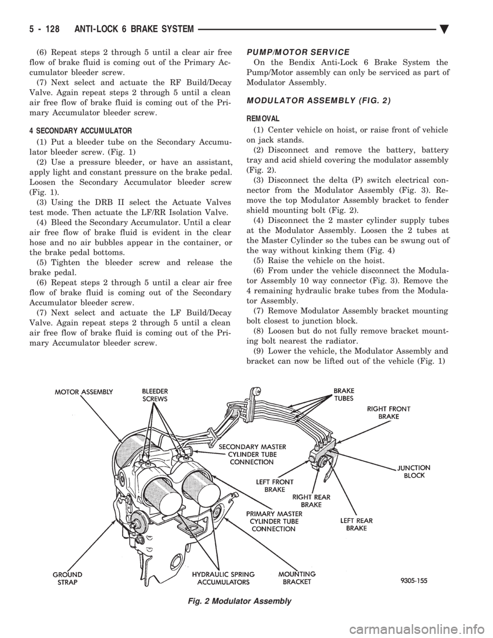
4 SECONDARY ACCUMULATOR (1) Put a bleeder tube on the Secondary Accumu-
lator bleeder screw. (Fig. 1) (2) Use a pressure bleeder, or have an assistant,
apply light and constant pressure on the brake pedal.
Loosen the Secondary Accumulator bleeder screw
(Fig. 1). (3) Using the DRB II select the Actuate Valves
test mode. Then actuate the LF/RR Isolation Valve. (4) Bleed the Secondary Accumulator. Until a clear
air free flow of brake fluid is evident in the clear
hose and no air bubbles appear in the container, or
the brake pedal bottoms. (5) Tighten the bleeder screw and release the
brake pedal. (6) Repeat steps 2 through 5 until a clear air free
flow of brake fluid is coming out of the Secondary
Accumulator bleeder screw. (7) Next select and actuate the LF Build/Decay
Valve. Again repeat steps 2 through 5 until a clean
air free flow of brake fluid is coming out of the Pri-
mary Accumulator bleeder screw.PUMP/MOTOR SERVICE
On the Bendix Anti-Lock 6 Brake System the
Pump/Motor assembly can only be serviced as part of
Modulator Assembly.
MODULATOR ASSEMBLY (FIG. 2)
REMOVAL
(1) Center vehicle on hoist, or raise front of vehicle
on jack stands. (2) Disconnect and remove the battery, battery
tray and acid shield covering the modulator assembly
(Fig. 2). (3) Disconnect the delta (P) switch electrical con-
nector from the Modulator Assembly (Fig. 3). Re-
move the top Modulator Assembly bracket to fender
shield mounting bolt (Fig. 2). (4) Disconnect the 2 master cylinder supply tubes
at the Modulator Assembly. Loosen the 2 tubes at
the Master Cylinder so the tubes can be swung out of
the way without kinking them (Fig. 4) (5) Raise the vehicle on the hoist.
(6) From under the vehicle disconnect the Modula-
tor Assembly 10 way connector (Fig. 3). Remove the
4 remaining hydraulic brake tubes from the Modula-
tor Assembly. (7) Remove Modulator Assembly bracket mounting
bolt closest to junction block. (8) Loosen but do not fully remove bracket mount-
ing bolt nearest the radiator. (9) Lower the vehicle, the Modulator Assembly and
bracket can now be lifted out of the vehicle (Fig. 1)
Fig. 2 Modulator Assembly
5 - 128 ANTI-LOCK 6 BRAKE SYSTEM Ä
Page 343 of 2438
COOLING SYSTEM
CONTENTS
page page
ACCESSORY DRIVE BELTS ............... 24
ENGINE BLOCK HEATER ................. 28
GENERAL INFORMATION .................. 1 SERVICE PROCEDURES
.................. 10
SPECIFICATIONS ....................... 29
GENERAL INFORMATION
Throughout this group, references may be made to
a particular vehicle by letter or number designation.
A chart showing the breakdown of these designations
is included in the Introduction Section at the front of
this service manual.
COOLING SYSTEM
The cooling system consists of an engine cooling
module, thermostat, coolant, a water pump to circu-
late the coolant. The engine cooling module may con-
sist of a radiator, electric fan motor, shroud, radiator
pressure cap, coolant reserve system, transmission oil
cooler, hoses, clamps, air condition condenser, trans-
mission oil lines and charge air cooler.
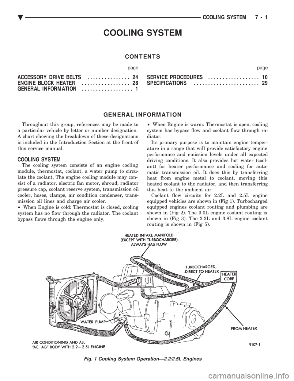
² When Engine is cold: Thermostat is closed, cooling
system has no flow through the radiator. The coolant
bypass flows through the engine only. ²
When Engine is warm: Thermostat is open, cooling
system has bypass flow and coolant flow through ra-
diator. Its primary purpose is to maintain engine temper-
ature in a range that will provide satisfactory engine
performance and emission levels under all expected
driving conditions. It also provides hot water (cool-
ant) for heater performance and cooling for auto-
matic transmission oil. It does this by transferring
heat from engine metal to coolant, moving this
heated coolant to the radiator, and then transferring
this heat to the ambient air. Coolant flow circuits for 2.2L and 2.5L engine
equipped vehicles are shown in (Fig 1). Turbocharged
equipped engines coolant routing and plumbing are
shown in (Fig 2). The 3.0L engine coolant routing is
shown in (Fig 3). The 3.3L and 3.8L engine coolant
routing is shown in (Fig 5).
Fig. 1 Cooling System OperationÐ2.2/2.5L Engines
Ä COOLING SYSTEM 7 - 1
Page 344 of 2438
TURBOCHARGER COOLANT ROUTING
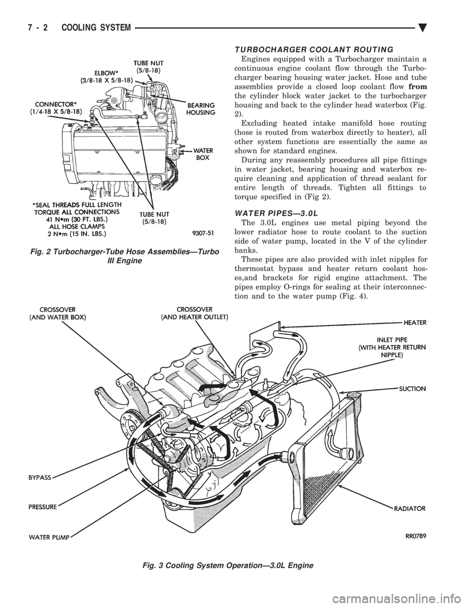
Engines equipped with a Turbocharger maintain a
continuous engine coolant flow through the Turbo-
charger bearing housing water jacket. Hose and tube
assemblies provide a closed loop coolant flow from
the cylinder block water jacket to the turbocharger
housing and back to the cylinder head waterbox (Fig.
2). Excluding heated intake manifold hose routing
(hose is routed from waterbox directly to heater), all
other system functions are essentially the same as
shown for standard engines. During any reassembly procedures all pipe fittings
in water jacket, bearing housing and waterbox re-
quire cleaning and application of thread sealant for
entire length of threads. Tighten all fittings to
torque specified in (Fig 2).
WATER PIPESÐ3.0L
The 3.0L engines use metal piping beyond the
lower radiator hose to route coolant to the suction
side of water pump, located in the V of the cylinder
banks. These pipes are also provided with inlet nipples for
thermostat bypass and heater return coolant hos-
es,and brackets for rigid engine attachment. The
pipes employ O-rings for sealing at their interconnec-
tion and to the water pump (Fig. 4).
Fig. 2 Turbocharger-Tube Hose AssembliesÐTurbo III Engine
Fig. 3 Cooling System OperationÐ3.0L Engine
7 - 2 COOLING SYSTEM Ä
Page 352 of 2438
SERVICE PROCEDURES INDEX
page page
Automatic Transmission Oil Coolers .......... 23
Coolant ................................ 14
Coolant Recovery System (CRS) ............. 17
Cooling System Drain, Clean, Flush and Refill . . 15
Electric Fan Motor ........................ 22
Engine Thermostats ....................... 13
Fan Shroud ............................. 23 Fans
.................................. 21
Radiator Hoses .......................... 21
Radiator Pressure Cap .................... 18
Radiators ............................... 18
Testing System for Leaks .................. 17
Water Pumps ........................... 10
WATER PUMPS
A quick test to tell whether or not the pump is
working is to see if the heater warms properly. A
defective pump will not be able to circulate heated
coolant through the long heater hose. The water pump on all models can be replaced
without discharging the air conditioning system.
WATER PUMPÐ2.2/2.5L ENGINE
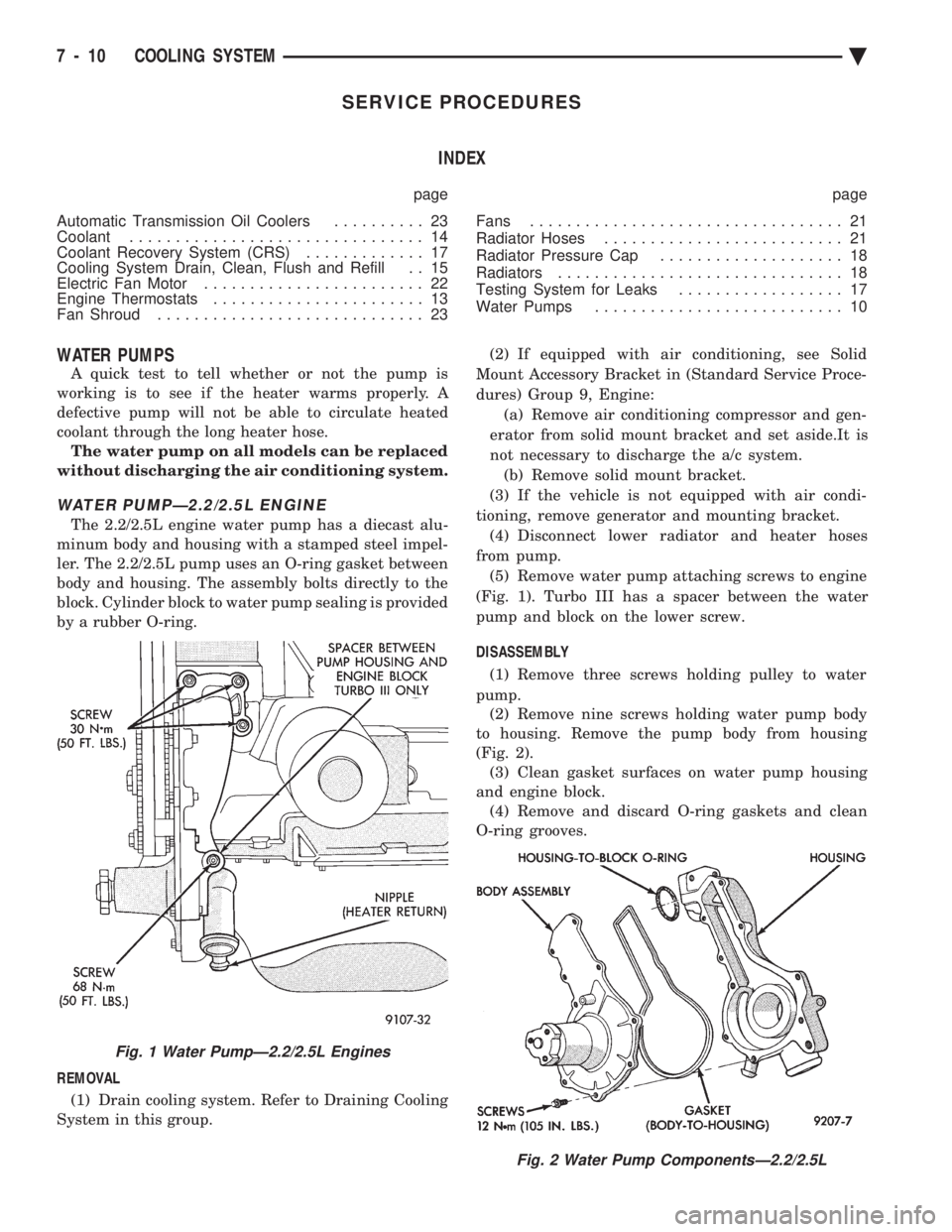
The 2.2/2.5L engine water pump has a diecast alu-
minum body and housing with a stamped steel impel-
ler. The 2.2/2.5L pump uses an O-ring gasket between
body and housing. The assembly bolts directly to the
block. Cylinder block to water pump sealing is provided
by a rubber O-ring.
REMOVAL (1) Drain cooling system. Refer to Draining Cooling
System in this group. (2) If equipped with air conditioning, see Solid
Mount Accessory Bracket in (Standard Service Proce-
dures) Group 9, Engine: (a) Remove air conditioning compressor and gen-
erator from solid mount bracket and set aside.It is
not necessary to discharge the a/c system. (b) Remove solid mount bracket.
(3) If the vehicle is not equipped with air condi-
tioning, remove generator and mounting bracket. (4) Disconnect lower radiator and heater hoses
from pump. (5) Remove water pump attaching screws to engine
(Fig. 1). Turbo III has a spacer between the water
pump and block on the lower screw.
DISASSEMBLY (1) Remove three screws holding pulley to water
pump. (2) Remove nine screws holding water pump body
to housing. Remove the pump body from housing
(Fig. 2). (3) Clean gasket surfaces on water pump housing
and engine block. (4) Remove and discard O-ring gaskets and clean
O-ring grooves.
Fig. 2 Water Pump ComponentsÐ2.2/2.5L
Fig. 1 Water PumpÐ2.2/2.5L Engines
7 - 10 COOLING SYSTEM Ä
Page 353 of 2438
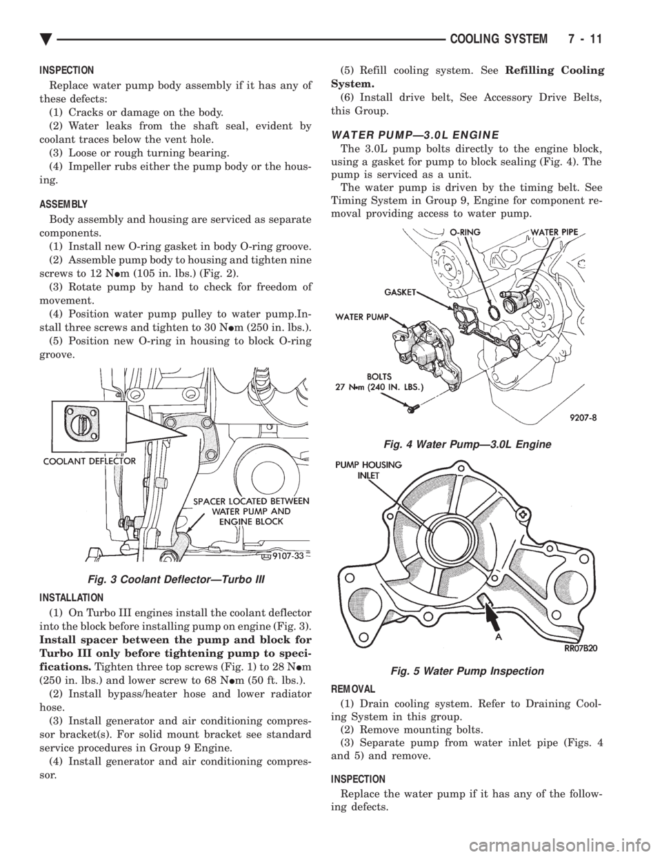
INSPECTION Replace water pump body assembly if it has any of
these defects: (1) Cracks or damage on the body.
(2) Water leaks from the shaft seal, evident by
coolant traces below the vent hole. (3) Loose or rough turning bearing.
(4) Impeller rubs either the pump body or the hous-
ing.
ASSEMBLY
Body assembly and housing are serviced as separate
components. (1) Install new O-ring gasket in body O-ring groove.
(2) Assemble pump body to housing and tighten nine
screws to 12 N Im (105 in. lbs.) (Fig. 2).
(3) Rotate pump by hand to check for freedom of
movement. (4) Position water pump pulley to water pump.In-
stall three screws and tighten to 30 N Im (250 in. lbs.).
(5) Position new O-ring in housing to block O-ring
groove.
INSTALLATION (1) On Turbo III engines install the coolant deflector
into the block before installing pump on engine (Fig. 3).
Install spacer between the pump and block for
Turbo III only before tightening pump to speci-
fications. Tighten three top screws (Fig. 1) to 28 N Im
(250 in. lbs.) and lower screw to 68 N Im (50 ft. lbs.).
(2) Install bypass/heater hose and lower radiator
hose. (3) Install generator and air conditioning compres-
sor bracket(s). For solid mount bracket see standard
service procedures in Group 9 Engine. (4) Install generator and air conditioning compres-
sor. (5) Refill cooling system. See
Refilling Cooling
System. (6) Install drive belt, See Accessory Drive Belts,
this Group.
WATER PUMPÐ3.0L ENGINE
The 3.0L pump bolts directly to the engine block,
using a gasket for pump to block sealing (Fig. 4). The
pump is serviced as a unit. The water pump is driven by the timing belt. See
Timing System in Group 9, Engine for component re-
moval providing access to water pump.
REMOVAL (1) Drain cooling system. Refer to Draining Cool-
ing System in this group. (2) Remove mounting bolts.
(3) Separate pump from water inlet pipe (Figs. 4
and 5) and remove.
INSPECTION Replace the water pump if it has any of the follow-
ing defects.
Fig. 4 Water PumpÐ3.0L Engine
Fig. 5 Water Pump Inspection
Fig. 3 Coolant DeflectorÐTurbo III
Ä COOLING SYSTEM 7 - 11
Page 355 of 2438
(5) Install drive belt. See Accessory Drive Belts
this group. (6) Install right front lower fender shield.
(7) Refill Cooling System. See Refilling Cooling
System in this section.
ENGINE THERMOSTATS
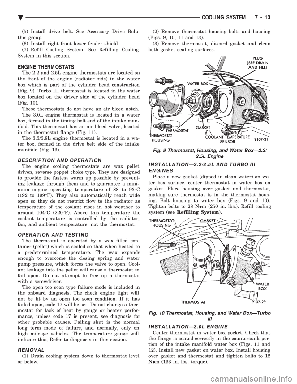
The 2.2 and 2.5L engine thermostats are located on
the front of the engine (radiator side) in the water
box which is part of the cylinder head construction
(Fig. 9). Turbo III thermostat is located in the water
box located on the driver side of the cylinder head
(Fig. 10). These thermostats do not have an air bleed notch.
The 3.0L engine thermostat is located in a water
box, formed in the timing belt end of the intake man-
ifold. This thermostat has an air bleed valve, located
in the thermostat flange (Fig. 11). The 3.3/3.8L engine thermostat is located in a wa-
ter box, formed in the drive belt side of the intake
manifold (Fig. 13).
DESCRIPTION AND OPERATION
The engine cooling thermostats are wax pellet
driven, reverse poppet choke type. They are designed
to provide the fastest warm up possible by prevent-
ing leakage through them and to guarantee a mini-
mum engine operating temperature of 88 to 93ÉC
(192 to 199ÉF). They also automatically reach wide
open so they do not restrict flow to the radiator as
temperature of the coolant rises in hot weather to
around 104ÉC (220ÉF). Above this temperature the
coolant temperature is controlled by the radiator,
fan, and ambient temperature, not the thermostat.
OPERATION AND TESTING
The thermostat is operated by a wax filled con-
tainer (pellet) which is sealed so that when heated to
a predetermined temperature. The wax expands
enough to overcome the closing spring and water
pump pressure, which forces the valve to open. Cool-
ant leakage into the pellet will cause a thermostat to
fail open. Do not attempt to free up a thermostat
with a screwdriver. The open too soon type failure mode is included in
the onboard diagnosis. The check engine light will
not be lit by an open too soon condition. If it has
failed open, code 17 will be set. Do not change a ther-
mostat for lack of heat by gauge or heater perfor-
mance, unless code 17 is present, see diagnosis for
other probable causes. Failing shut is the normal
long term mode of failure, and normally, only on
high mileage vehicles. The temperature gauge will
indicate this, Refer to diagnosis in this section.
REMOVAL
(1) Drain cooling system down to thermostat level
or below. (2) Remove thermostat housing bolts and housing
(Figs. 9, 10, 11 and 13). (3) Remove thermostat, discard gasket and clean
both gasket sealing surfaces.
INSTALLATIONÐ2.2/2.5L AND TURBO III ENGINES
Place a new gasket (dipped in clean water) on wa-
ter box surface, center thermostat in water box on
gasket. Place housing over gasket and thermostat,
making sure thermostat is in the thermostat hous-
ing. Bolt housing to water box (Figs. 9 and 10).
Tighten bolts to 28 N Im (250 in. lbs.). Refill cooling
system (see Refilling System ).
INSTALLATIONÐ3.0L ENGINE
Center thermostat in water box pocket. Check that
the flange is seated correctly in the countersunk por-
tion of the intake manifold water box (Figs. 11 and
12). Install new gasket on water box. Install housing
over gasket and thermostat and tighten bolts to 12
N Im (133 in. lbs. torque).
Fig. 9 Thermostat, Housing, and Water BoxÐ2.2/
2.5L Engine
Fig. 10 Thermostat, Housing, and Water BoxÐTurbo III
Ä COOLING SYSTEM 7 - 13