1993 CHEVROLET DYNASTY service
[x] Cancel search: servicePage 1568 of 2438
The MOPAR Silicone Rubber Adhesive Sealant
gasket material or equivalent should be applied in a
continuous bead approximately 3mm (0.120 inch) in
diameter. All mounting holes must be circled. For
corner sealing, a 3.17 or 6.35 mm (1/8 or 1/4 inch.)
drop is placed in the center of the gasket contact
area. Uncured sealant may be removed with a shop
towels. Components should be torqued in place while
the sealant is still wet to the touch (within 10 min-
utes). The usage of a locating dowel is recommended
during assembly to prevent smearing of material off
location.
CRANKSHAFT SPROCKET BOLT ACCESS PLUG
An Access plug is located in the right inner fender
shield. Remove the plug and insert proper size
socket, extension and rachet, when crankshaft rota-
tion is necessary.
ENGINE PERFORMANCE
If a loss of performance is noticed, ignition timing
should be checked. If ignition timing is retarded by
9, 18 or 27É indicating 1, 2 or 3 (timing belt or chain)
teeth may have skipped, then, camshaft and acces-
sory shaft timing with the crankshaft should be
checked. Refer to Engine Timing Sprockets and Oil
Seals of the Engine Section. To provide best vehicle performance and lowest ve-
hicle emissions, it is most important that the tune-up
be done accurately. Use the specifications listed on
the Vehicle Emission Control Information label
found in the engine compartment. (1) Test cranking amperage draw. See Starting
Motor Cranking Amperage Draw Electrical Section
of this manual. (2) Tighten the intake manifold bolts to specifica-
tions. (3) Perform cylinder compression test.(a) Check engine oil level and add oil if neces-
sary. (b) Drive the vehicle until engine reaches normal
operating temperature. (c) Select a route free from traffic and other
forms of congestion, observe all traffic laws, and ac-
celerate through the gears several times briskly.
CAUTION: Do not overspeed the engine. The higher
engine speed may help clean out valve seat deposits
which can prevent accurate compression readings.
(d) Remove all spark plugs from engine. As
spark plugs are being removed, check electrodes for
abnormal firing indicators fouled, hot, oily, etc.
Record cylinder number of spark plug for future
reference. (e) Disconnect coil wire from distributor and se-
cure to good ground to prevent a spark from start- ing a fire (Conventional Ignition System). For Direct
Ignition System DIS disconnect the coil connector. (f) Be sure throttle blade is fully open during the
compression check. (g) Insert compression gage adaptor into the #1
spark plug hole in cylinder head. Crank engine until
maximum pressure is reached on gage. Record this
pressure as #1 cylinder pressure. (h) Repeat Step G for all remaining cylinders.
(i) Compression should not be less than (689kPa)
100 psi and not vary more than 25 percent from
cylinder to cylinder. (j) If one or more cylinders have abnormally low
compression pressures, repeat steps 3b through 3h. (k) If the same cylinder or cylinders repeat an
abnormally low reading on the second compression
test, it could indicate the existence of a problem in
the cylinder in question.
The recommended compression pressures are
to be used only as a guide to diagnosing engine
problems. An engine should not be disassembled
to determine the cause of low compression un-
less some malfunction is present. (4) Clean or replace spark plugs as necessary and
adjust gap as specified in Electrical Group 8. Tighten to
specifications. (5) Test resistance of spark plug cables. Refer to
Ignition System Secondary Circuit Inspection Electri-
cal Section Group 8. (6) Inspect the primary wire. Test coil output volt-
age, primary and secondary resistance. Replace parts
as necessary. Refer to Ignition System and make nec-
essary adjustment. (7) Ignition timing should be set to specifications.
(See Specification Label in engine compartment). (8) Test fuel pump for pressure and vacuum. Refer to
Fuel System Group 14, Specifications. (9) The air filter elements should be replaced as
specified in Lubrication and Maintenance, Group 0. (10) Inspect crankcase ventilation system as out
lined in Lubrication and Maintenance, Group 0. For
emission controls see Emission Controls Group 25 for
service procedures. (11) Inspect and adjust accessory belt drives refer-
ring to Accessory Belt Drive in Cooling System, Group
7 for proper adjustments. (12) Road test vehicle as a final test.
HONING CYLINDER BORES
Before honing, stuff plenty of clean shop towels
under the bores, over the crankshaft to keep abrasive
materials from entering crankcase area. (1) Used carefully, the cylinder bore resizing hone
C-823 equipped with 220 grit stones, is the best tool for
this job. In addition to deglazing, it will reduce taper
and out-of-round as well as removing light
9 - 2 ENGINE Ä
Page 1574 of 2438
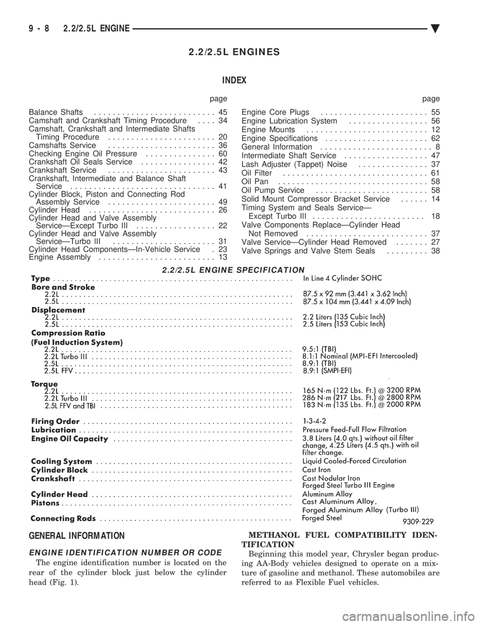
2.2/2.5L ENGINES INDEX
page page
Balance Shafts .......................... 45
Camshaft and Crankshaft Timing Procedure .... 34
Camshaft, Crankshaft and Intermediate Shafts Timing Procedure ....................... 20
Camshafts Service ....................... 36
Checking Engine Oil Pressure ............... 60
Crankshaft Oil Seals Service ................ 42
Crankshaft Service ....................... 43
Crankshaft, Intermediate and Balance Shaft Service ............................... 41
Cylinder Block, Piston and Connecting Rod Assembly Service ....................... 49
Cylinder Head ........................... 26
Cylinder Head and Valve Assembly ServiceÐExcept Turbo III ................. 22
Cylinder Head and Valve Assembly ServiceÐTurbo III ...................... 31
Cylinder Head ComponentsÐIn-Vehicle Service . 23
Engine Assembly ......................... 13 Engine Core Plugs
....................... 55
Engine Lubrication System ................. 56
Engine Mounts .......................... 12
Engine Specifications ...................... 62
General Information ........................ 8
Intermediate Shaft Service .................. 47
Lash Adjuster (Tappet) Noise ............... 37
Oil Filter ............................... 61
Oil Pan ................................ 58
Oil Pump Service ........................ 58
Solid Mount Compressor Bracket Service ...... 14
Timing System and Seals ServiceÐ Except Turbo III ........................ 18
Valve Components ReplaceÐCylinder Head Not Removed .......................... 37
Valve ServiceÐCylinder Head Removed ....... 27
Valve Springs and Valve Stem Seals ......... 38
GENERAL INFORMATION
ENGINE IDENTIFICATION NUMBER OR CODE
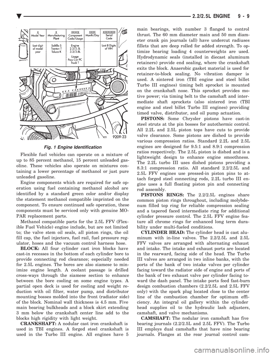
The engine identification number is located on the
rear of the cylinder block just below the cylinder
head (Fig. 1). METHANOL FUEL COMPATIBILITY IDEN-
TIFICATION Beginning this model year, Chrysler began produc-
ing AA-Body vehicles designed to operate on a mix-
ture of gasoline and methanol. These automobiles are
referred to as Flexible Fuel vehicles.
2.2/2.5L ENGINE SPECIFICATION
9 - 8 2.2/2.5L ENGINE Ä
Page 1575 of 2438
Flexible fuel vehicles can operate on a mixture of
up to 85 percent methanol, 15 percent unleaded gas-
oline. These vehicles also operate on mixtures con-
taining a lower percentage of methanol or just pure
unleaded gasoline. Engine components which are required for safe op-
eration using fuel containing methanol alcohol are
identified by a standard green color and/or display
the statement methanol compatible imprinted on the
component. To ensure continued safe operation, these
components must be serviced only with genuine MO-
PAR replacement parts. Methanol compatible parts for the 2.5L FFV (Flex-
ible Fuel Vehicle) engine include, but are not limited
to; the valve stem oil seals, all piston rings, the oil
fill cap, the fuel injectors, fuel rail, fuel pressure reg-
ulator, hoses and the vacuum control harness hose. BLOCK: All four cylinder cast iron blocks have
cast-in recesses in the bottom of each cylinder bore to
provide connecting rod clearance; especially needed
for 2.5L engines. The bores are also siamese to min-
imize engine length. A coolant passage is drilled
cross-ways through the siamese section to enhance
between the bore cooling on some engine types. A
partial open deck is used for cooling and weight re-
duction with oil filter, water pump, and distributor
mounting bosses molded into the front (radiator side)
of the block. Nominal wall thickness is 4.5 mm. Five
main bearing bulkheads and a block skirt extending
3 mm below the crankshaft center line add to the
blocks high rigidity with light weight. CRANKSHAFT: A nodular cast iron crankshaft is
used in TBI engines. A forged steel crankshaft is
used in the Turbo III engine. All engines have 5 main bearings, with number 3 flanged to control
thrust. The 60 mm diameter main and 50 mm diam-
eter crank pin journals (all) have undercut radiuses
fillets that are deep rolled for added strength. To op-
timize bearing loading 4 counterweights are used.
Hydrodynamic seals (installed in diecast aluminum
retainers) provide end sealing, where the crankshaft
exits the block. Anaerobic gasket material is used for
retainer-to-block sealing. No vibration damper is
used. A sintered iron (TBI engine and steel billet
Turbo III engines) timing belt sprocket is mounted
on the crankshaft nose. This sprocket provides mo-
tive power; via timing belt to the camshaft and inter-
mediate shaft sprockets (also sintered iron (TBI
engine and steel billet Turbo III engines) providing
timed valve, distributor, and oil pump actuation. PISTONS: Some Chrysler pistons have cast-in
steel struts at the pin bosses for autothermic control.
All 2.2L and 2.5L piston tops have cuts to provide
valve clearance. Some pistons are dished to provide
various compression ratios. Standard 2.2L and 2.5L
engines are designed for 9.5:1 and 8.9:1 compression
ratios respectively. The 2.5L piston is dished and is a
lightweight design to enhance engine smoothness.
The 2.2L turbo III uses dished pistons providing a
8.3:1 compression ratio. All standard 2.2/2.5L and
2.5L FFV engines use pressed-in piston pins to at-
tach forged steel connecting rods, 2.2L turbo III en-
gine uses a full floating piston pin and connecting
rod assembly. PISTONS RINGS: The 2.2/2.5L engines share
common piston rings throughout, including molybde-
num filled top ring for reliable compression sealing
and a tapered faced intermediate ring for additional
cylinder pressure control. The 2.5L FFV engine fea-
ture all chrome rings for enhanced long term dura-
bility under multi-fueled conditions. CYLINDER HEAD: The cylinder head is cast alu-
minum with in-line valves. The 2.2/2.5L and 2.5L
FFV valves are arranged with alternating exhaust
and intake. The intake and exhaust ports are located
in the rearward, facing side of the head. The Turbo
III valves are arranged in two inline banks, with the
ports of the bank of two intake valves per cylinder
facing toward the radiator side of engine and ports of
the bank of two exhaust valve per cylinder facing to-
ward the dash panel. The intake ports feed fast-burn
design combustion chambers (2.2/2.5L and 2.5L FFV
only) with the spark plug located close to the center
line of the combustion chamber for optimum effi-
ciency. An integral oil gallery within the cylinder
head supplies oil to the hydraulic lash adjusters,
camshaft, and valve mechanisms. CAMSHAFT: The nodular iron camshaft has five
bearing journals (2.2/2.5L and 2.5L FFV). The Turbo
III employs dual camshafts that have nine bearing
journals. Flanges at the rear journal control cam-
Fig. 1 Engine Identification
Ä 2.2/2.5L ENGINE 9 - 9
Page 1580 of 2438
CAUTION: Make sure clutch cable has been discon-
nected. (20) Remove front engine mount screw and nut.
(21) Remove manual transmission damper.
(22) Remove left insulator through bolt from inside
wheelhouse or insulator bracket to transmission
screws. (23) Remove engine from vehicle.
INSTALLATION
(1) Install hoist to the engine and lower engine
into the engine compartment. SEE: ENGINE MOUNT RUBBER INSULATORS,
THIS GROUP. (2) Align engine mounts and install but do not
tighten until all mounting bolts have been installed.
(3) Install transmission case to cylinder block
mounting screws. Tighten to 95 N Im (70 ft. lbs.)
torque. (4) Remove engine hoist and transmission holding
fixture. (5) Install ground strap.
(6) Install right inner splash shield.
(7) Connect starter. See Electrical Group 8 for in-
stallation. (8) Connect exhaust system. See Exhaust Systems
Group 11 for installation. (9) Manual Transmission: Install transmission
case lower cover. Automatic Transmission: Remove C clamp from
torque converter housing. Align flexplate to torque
converter and install mounting screws. Tighten to 75
N Im (55 ft. lbs.) torque.
(10) Manual Transmission: Connect clutch cable.
See Clutch Group 6. (11) Install power steering pump. Refer to Cooling
System Group 7, Accessory Drive Section for belt
tension adjustment. (12) Connect fuel line, heater hose, and accelerator
cable. (13) Connect all electrical connections and har-
nesses at throttle body and engine. (14) Install oil filter. Fill engine crankcase with
proper oil to correct level. (15) Install air conditioning compressor (if
equipped). See Heater and Air Conditioning, Group
24 for installation. (16) Install air cleaner and hoses.
(17) Install radiator and shroud assembly . Install
radiator hoses. Fill cooling system. See Cooling Sys-
tem Group 7 for filling procedure. (18) Install hood.
(19) Connect battery.
(20) Start engine and run until operating temper-
ature is reached. (21) Adjust transmission linkage, if necessary.
SOLID MOUNT COMPRESSOR BRACKET SERVICE
When service procedures require solid mount
bracket removal and installation for example: cylin-
der head removal, etc., it is important that bracket
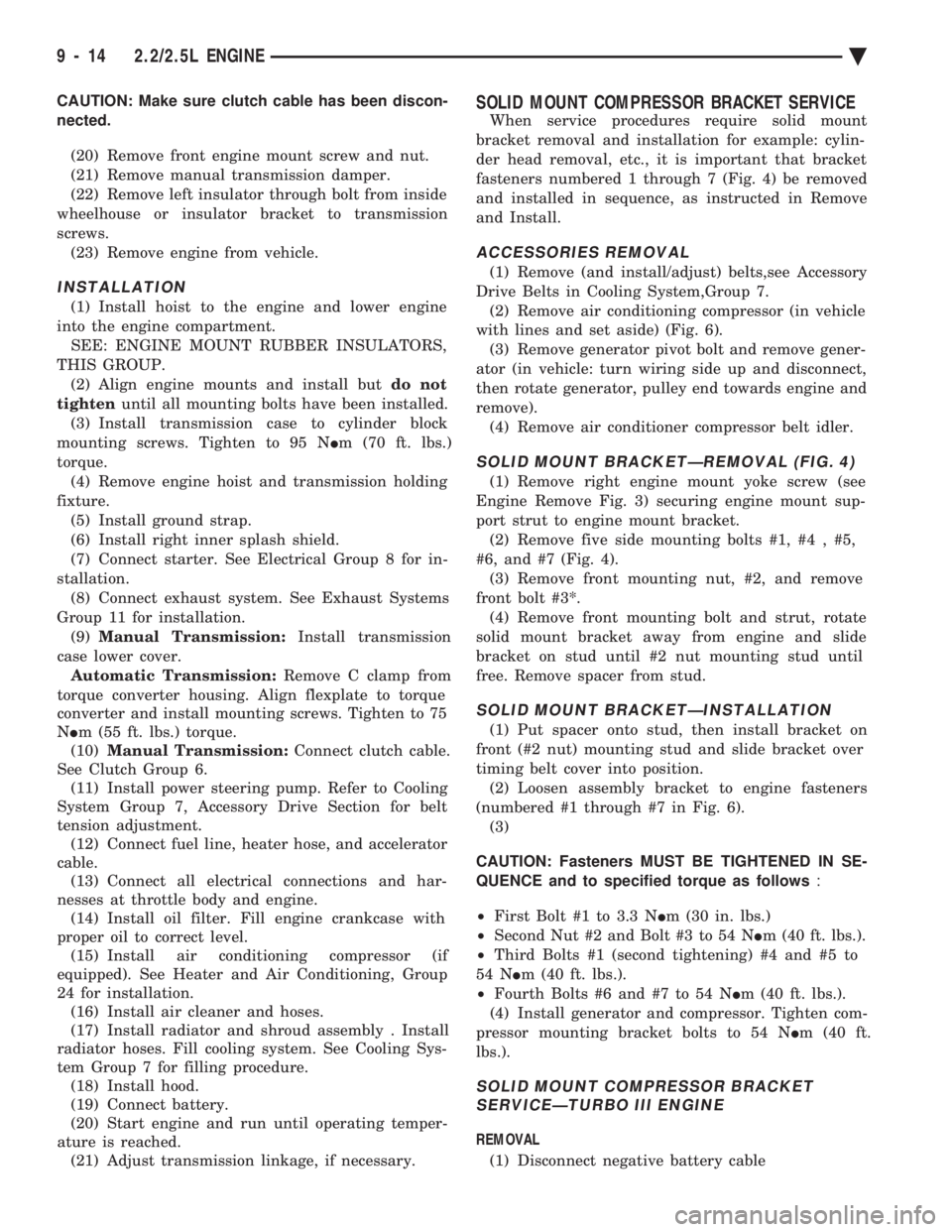
fasteners numbered 1 through 7 (Fig. 4) be removed
and installed in sequence, as instructed in Remove
and Install.
ACCESSORIES REMOVAL
(1) Remove (and install/adjust) belts,see Accessory
Drive Belts in Cooling System,Group 7. (2) Remove air conditioning compressor (in vehicle
with lines and set aside) (Fig. 6). (3) Remove generator pivot bolt and remove gener-
ator (in vehicle: turn wiring side up and disconnect,
then rotate generator, pulley end towards engine and
remove). (4) Remove air conditioner compressor belt idler.
SOLID MOUNT BRACKETÐREMOVAL (FIG. 4)
(1) Remove right engine mount yoke screw (see
Engine Remove Fig. 3) securing engine mount sup-
port strut to engine mount bracket. (2) Remove five side mounting bolts #1, #4 , #5,
#6, and #7 (Fig. 4). (3) Remove front mounting nut, #2, and remove
front bolt #3*. (4) Remove front mounting bolt and strut, rotate
solid mount bracket away from engine and slide
bracket on stud until #2 nut mounting stud until
free. Remove spacer from stud.
SOLID MOUNT BRACKETÐINSTALLATION
(1) Put spacer onto stud, then install bracket on
front (#2 nut) mounting stud and slide bracket over
timing belt cover into position. (2) Loosen assembly bracket to engine fasteners
(numbered #1 through #7 in Fig. 6). (3)
CAUTION: Fasteners MUST BE TIGHTENED IN SE-
QUENCE and to specified torque as follows :
² First Bolt #1 to 3.3 N Im (30 in. lbs.)
² Second Nut #2 and Bolt #3 to 54 N Im (40 ft. lbs.).
² Third Bolts #1 (second tightening) #4 and #5 to
54 N Im (40 ft. lbs.).
² Fourth Bolts #6 and #7 to 54 N Im (40 ft. lbs.).
(4) Install generator and compressor. Tighten com-
pressor mounting bracket bolts to 54 N Im (40 ft.
lbs.).
SOLID MOUNT COMPRESSOR BRACKET SERVICEÐTURBO III ENGINE
REMOVAL
(1) Disconnect negative battery cable
9 - 14 2.2/2.5L ENGINE Ä
Page 1582 of 2438
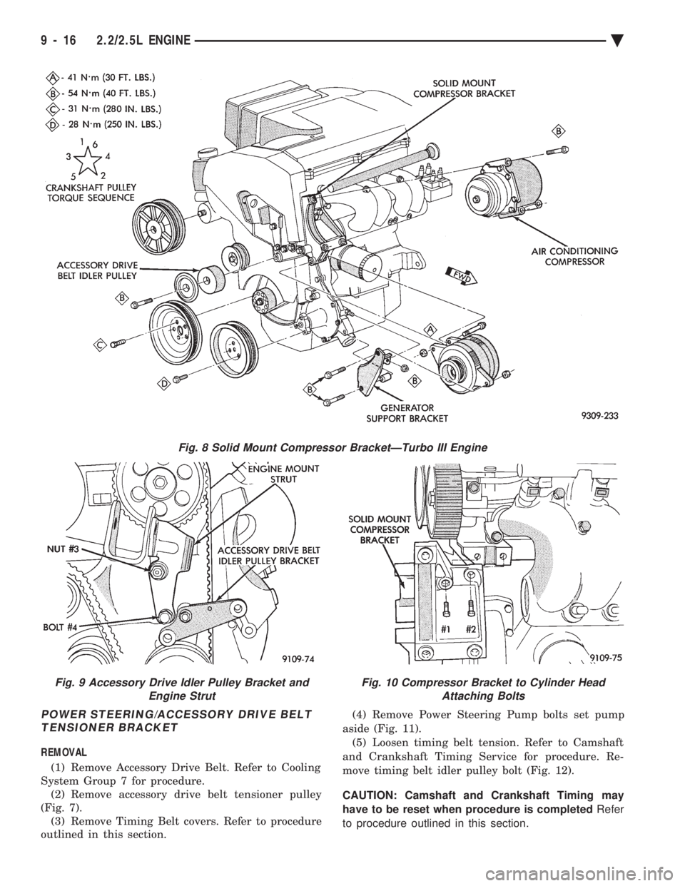
POWER STEERING/ACCESSORY DRIVE BELT TENSIONER BRACKET
REMOVAL
(1) Remove Accessory Drive Belt. Refer to Cooling
System Group 7 for procedure. (2) Remove accessory drive belt tensioner pulley
(Fig. 7). (3) Remove Timing Belt covers. Refer to procedure
outlined in this section. (4) Remove Power Steering Pump bolts set pump
aside (Fig. 11). (5) Loosen timing belt tension. Refer to Camshaft
and Crankshaft Timing Service for procedure. Re-
move timing belt idler pulley bolt (Fig. 12).
CAUTION: Camshaft and Crankshaft Timing may
have to be reset when procedure is completed Refer
to procedure outlined in this section.
Fig. 8 Solid Mount Compressor BracketÐTurbo III Engine
Fig. 9 Accessory Drive Idler Pulley Bracket and Engine StrutFig. 10 Compressor Bracket to Cylinder HeadAttaching Bolts
9 - 16 2.2/2.5L ENGINE Ä
Page 1584 of 2438
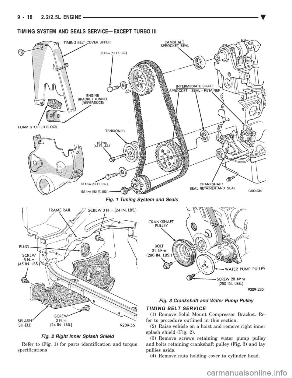
TIMING SYSTEM AND SEALS SERVICEÐEXCEPT TURBO III
Refer to (Fig. 1) for parts identification and torque
specifications
TIMING BELT SERVICE
(1) Remove Solid Mount Compressor Bracket. Re-
fer to procedure outlined in this section. (2) Raise vehicle on a hoist and remove right inner
splash shield (Fig. 2). (3) Remove screws retaining water pump pulley
and bolts retaining crankshaft pulley (Fig. 3) and lay
pullies aside. (4) Remove nuts holding cover to cylinder head.
Fig. 2 Right Inner Splash Shield
Fig. 3 Crankshaft and Water Pump Pulley
Fig. 1 Timing System and Seals
9 - 18 2.2/2.5L ENGINE Ä
Page 1588 of 2438
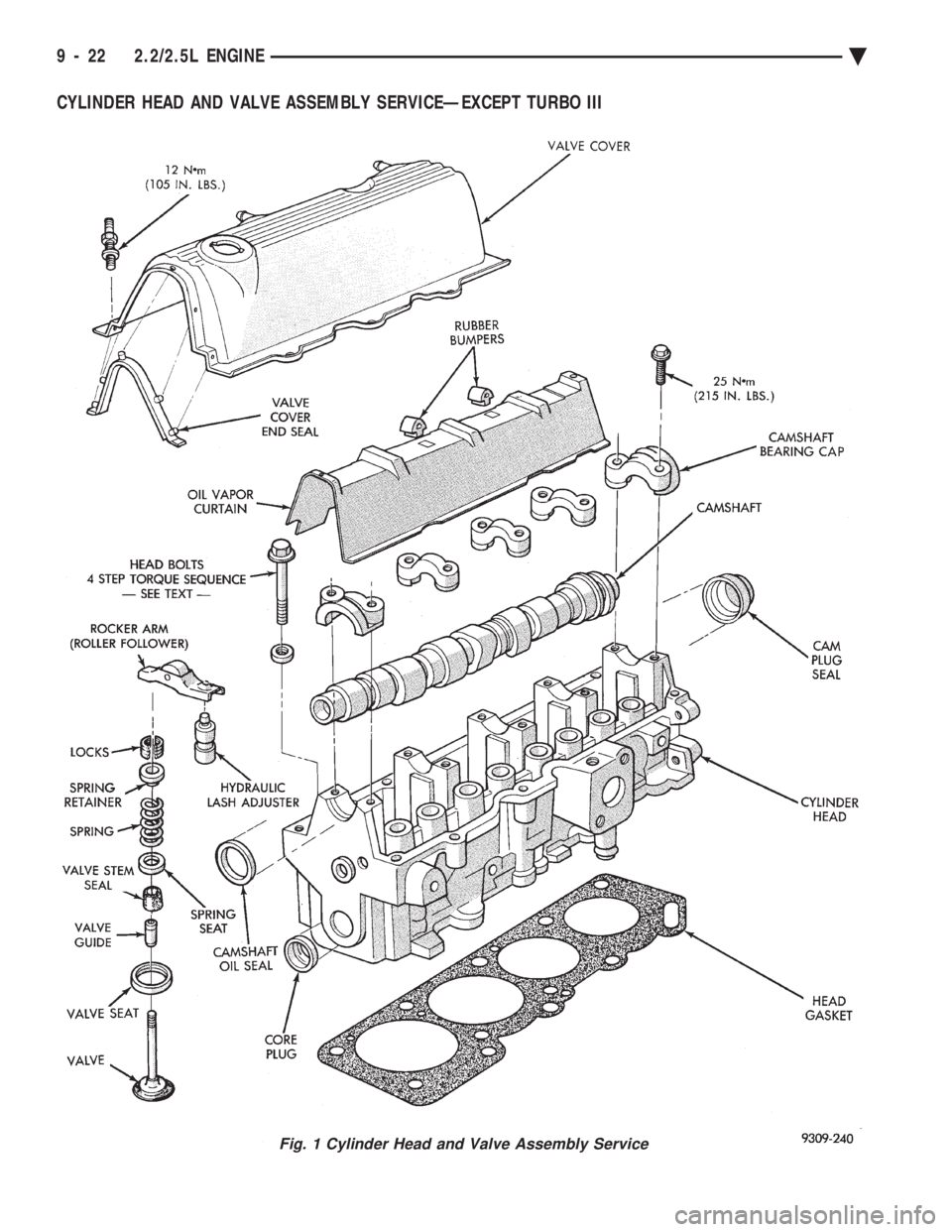
CYLINDER HEAD AND VALVE ASSEMBLY SERVICEÐEXCEPT TURBO III
Fig. 1 Cylinder Head and Valve Assembly Service
9 - 22 2.2/2.5L ENGINE Ä
Page 1589 of 2438
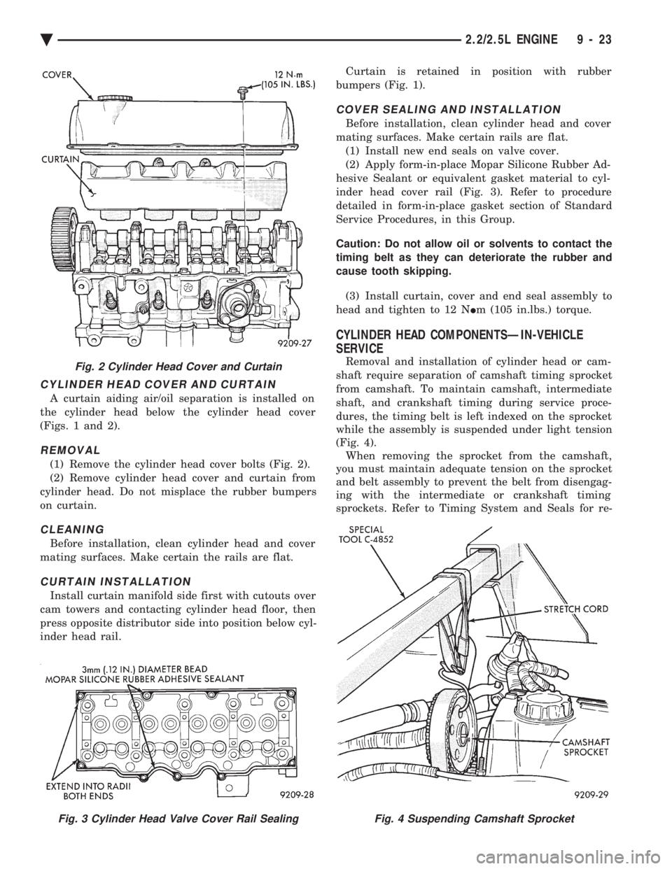
CYLINDER HEAD COVER AND CURTAIN
A curtain aiding air/oil separation is installed on
the cylinder head below the cylinder head cover
(Figs. 1 and 2).
REMOVAL
(1) Remove the cylinder head cover bolts (Fig. 2).
(2) Remove cylinder head cover and curtain from
cylinder head. Do not misplace the rubber bumpers
on curtain.
CLEANING
Before installation, clean cylinder head and cover
mating surfaces. Make certain the rails are flat.
CURTAIN INSTALLATION
Install curtain manifold side first with cutouts over
cam towers and contacting cylinder head floor, then
press opposite distributor side into position below cyl-
inder head rail. Curtain is retained in position with rubber
bumpers (Fig. 1).
COVER SEALING AND INSTALLATION
Before installation, clean cylinder head and cover
mating surfaces. Make certain rails are flat. (1) Install new end seals on valve cover.
(2) Apply form-in-place Mopar Silicone Rubber Ad-
hesive Sealant or equivalent gasket material to cyl-
inder head cover rail (Fig. 3). Refer to procedure
detailed in form-in-place gasket section of Standard
Service Procedures, in this Group.
Caution: Do not allow oil or solvents to contact the
timing belt as they can deteriorate the rubber and
cause tooth skipping.
(3) Install curtain, cover and end seal assembly to
head and tighten to 12 N Im (105 in.lbs.) torque.
CYLINDER HEAD COMPONENTSÐIN-VEHICLE
SERVICE
Removal and installation of cylinder head or cam-
shaft require separation of camshaft timing sprocket
from camshaft. To maintain camshaft, intermediate
shaft, and crankshaft timing during service proce-
dures, the timing belt is left indexed on the sprocket
while the assembly is suspended under light tension
(Fig. 4). When removing the sprocket from the camshaft,
you must maintain adequate tension on the sprocket
and belt assembly to prevent the belt from disengag-
ing with the intermediate or crankshaft timing
sprockets. Refer to Timing System and Seals for re-Fig. 2 Cylinder Head Cover and Curtain
Fig. 3 Cylinder Head Valve Cover Rail SealingFig. 4 Suspending Camshaft Sprocket
Ä 2.2/2.5L ENGINE 9 - 23