1993 CHEVROLET DYNASTY service
[x] Cancel search: servicePage 559 of 2438

VEHICLE SPEED SENSOR TEST
For testing of the vehicle speed sensor and related
components using DRB II, refer to the appropriate
Powertrain Diagnostics Test Procedure Manual.
PRINTED CIRCUIT BOARD REPLACEMENT
(1) Remove cluster bezel.
(2) Remove instrument cluster.
(3) Remove tachometer drive module, if equipped.
(4) Remove six retaining screws (Fig. 18).
(5) Twist out all illumination and warning lamp
sockets. (6) Pull printed circuit board from cluster housing.
(7) For installation reverse above procedures. Posi-
tion printed circuit board on cluster housing, being
certain that all gauge pins are inserted correctly.
CLUSTER LAMP REPLACEMENT
Illumination Lamp Chart shows cluster as viewed
from rear. However, all lamps must be replaced by
removing cluster from instrument panel (Fig. 19).
SWITCH AND PANEL COMPONENT SERVICE
LOWER STEERING COLUMN COVER REPLACEMENT
(1) Disconnect park brake release rod from the
park brake handle. (2) Remove two screws attaching hood release (Fig.
20). (3) Remove fuse access door and remove steering
column cover attaching screw located directly above
the fuse block. (4) Remove six screws around outside of steering
column cover. (5) Remove steering column cover.
(6) For installation reverse above procedures.
CENTER MODULE LOWER COVER REPLACEMENT
(1) Open ash receiver and remove center module
bezel. (2) Remove module cover to instrument panel re-
taining screws (Fig. 20). (3) Remove module cover from vehicle.
(4) For installation reverse above procedures.
CENTER MODULE BEZEL REPLACEMENT
(1) Open ash receiver.
(2) Grip module bezel around outer edges and pull
rearward to release six spring-type retaining clips
(Fig. 20). (3) For installation position spring clips to instru-
ment panel and push firmly until seated. (4) Close ash receiver.
Fig. 17 Vehicle Speed Sensor Removal
Fig. 18 Printed Circuit Board
Fig. 19 Instrument Cluster Illumination Lamps
Ä INSTRUMENT PANEL AND GAUGES 8E - 67
Page 596 of 2438
COMPACT DISC PLAYER
WARNING: USE OF THE CONTROLS, ADJUST-
MENTS, OR SERVICE PROCEDURES NOT SPECI-
FIED HERE OR IN THE OWNER MANUAL MAY
RESULT IN HAZARDOUS RADIATION EXPOSURE.
REPAIR PROCEDURES SHOULD ONLY BE PER-
FORMED BY A TRAINED TECHNICIAN.
DIAGNOSIS TEST
Power to the compact disc player is supplied by the
radio through the CD interface cable. The compact
disc player will only work with the radio system
turned ON. When a compact disc is inserted with the
label side facing up, the disc is automatically loaded
and will begin to play. The CD player may eject the disc with a display of
E under the following conditions:
² The surface of the disc is dirty or wet
² The disc was inserted with the label side facing
down
² The disc is defective
² The CD player may skip or mute while playing a
disc under severe vibration conditions example pot
holes, railroad tracks, etc.
² If the CD player becomes too hot at temperatures
above 60ÉC (140 ÉF) the CD player will shut down
with a display of HOT until it cools down. Refer to
the Audio Diagnostic Charts.
COMPACT DISC PLAYER REPLACEMENT
With intergral compact disc player refer to Radio
Removal.
AJ BODY
(1) Remove center instrument panel bezel by pull-
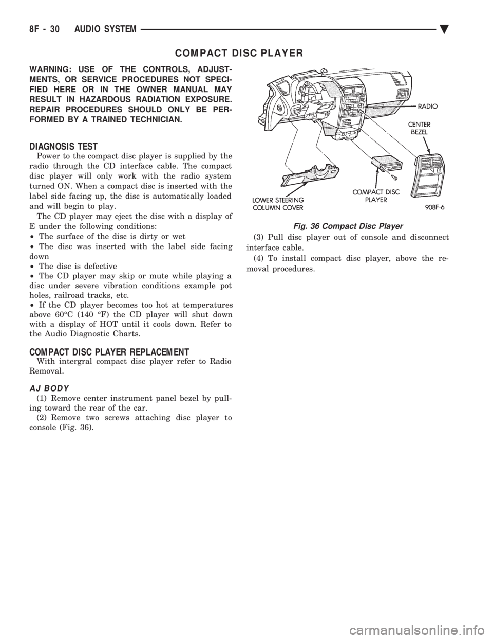
ing toward the rear of the car. (2) Remove two screws attaching disc player to
console (Fig. 36). (3) Pull disc player out of console and disconnect
interface cable. (4) To install compact disc player, above the re-
moval procedures.
Fig. 36 Compact Disc Player
8F - 30 AUDIO SYSTEM Ä
Page 621 of 2438
WINDSHIELD WIPER AND WASHER SYSTEMS
CONTENTS
page page
GENERAL WIPER INFORMATION ........... 1
INTERMITTENT WINDSHIELD WIPER MOTOR AND SWITCH SERVICE PROCEDURES .... 12
WINDSHIELD WASHERS ................. 17 WINDSHIELD WIPER BLADE AND ARM SERVICE
PROCEDURES ......................... 1
WINDSHIELD WIPER MOTOR AND LINKAGE ASSEMBLY SERVICE PROCEDURES ....... 3
GENERAL WIPER INFORMATION
WARNING: ON VEHICLES EQUIPPED WITH AIR-
BAG, SEE GROUP 8M, RESTRAINT SYSTEMS FOR
STEERING WHEEL OR COLUMN REMOVAL PROCE-
DURES.
The windshield wipers can be operated with the
windshield wiper switch only when the ignition
switch is in the ACCESSORY or IGNITION position.
A fuse, located in the fuse block, protects the cir-
cuitry of the wiper system and the vehicle. The wiper motor has permanent magnet fields. The speeds are determined by current flow to the appro-
priate set of brushes. The intermittent wipe system, in addition to low
and high speed, has a delay mode. The delay mode
has a range of 2 to 15 seconds. This is accomplished
by a variable resistor in the wiper switch and is con-
trolled electrically by a relay. The wiper system completes the wipe cycle when
the switch is turned OFF. The blades park in the
lowest portion of the wipe pattern.
WINDSHIELD WIPER BLADE AND ARM SERVICE PROCEDURES
WIPER BLADES
Wiper blades, exposed to the weather for a long pe-
riod of time, tend to lose their wiping effectiveness.
Periodic cleaning of the wiper blade is suggested to
remove the accumulation of salt and road film. The
wiper blades, arms, and windshield should be cleaned
with a sponge or cloth and a mild detergent or nona-
brasive cleaner. If the blades continue to streak or
smear, they should be replaced.
WIPER BLADE ELEMENT CHANGE
(1) Turn wiper switch ON, position blades to a con-
venient place by turning the ignition switch ON and
OFF. (2) Lift wiper arm to raise blade off glass.
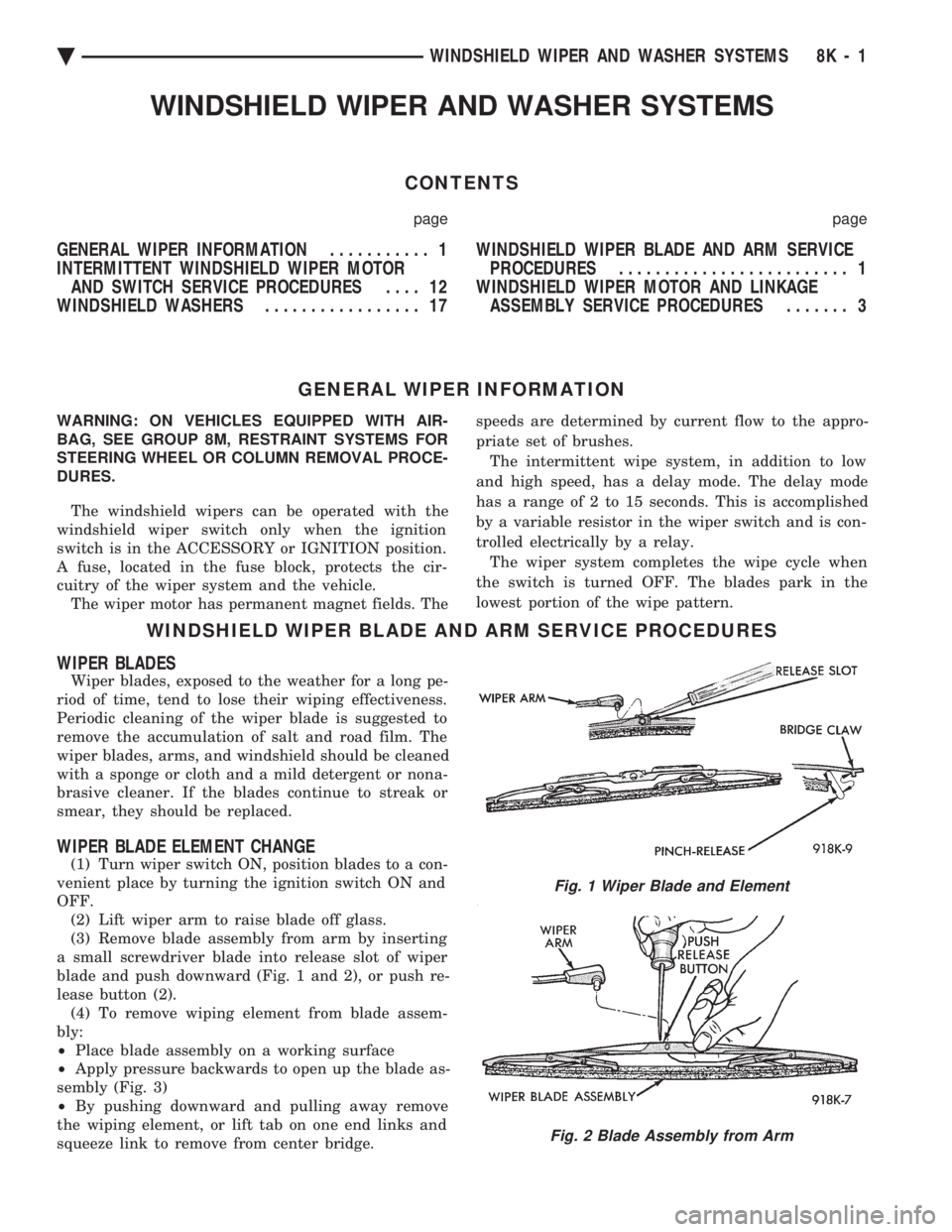
(3) Remove blade assembly from arm by inserting
a small screwdriver blade into release slot of wiper
blade and push downward (Fig. 1 and 2), or push re-
lease button (2). (4) To remove wiping element from blade assem-
bly:
² Place blade assembly on a working surface
² Apply pressure backwards to open up the blade as-
sembly (Fig. 3)
² By pushing downward and pulling away remove
the wiping element, or lift tab on one end links and
squeeze link to remove from center bridge.
Fig. 1 Wiper Blade and Element
Fig. 2 Blade Assembly from Arm
Ä WINDSHIELD WIPER AND WASHER SYSTEMS 8K - 1
Page 623 of 2438
(3) Secure arm to pivot with attaching nut and
tighten 17 to 22 N Im (155 to 195 in. lbs.) torque.
(4) Close head cover and remove pin from arm pin
hole.
WIPER ARM ADJUSTMENT
FRONT ARM ADJUSTMENT
(1) Cycle the wiper motor into the PARK position.
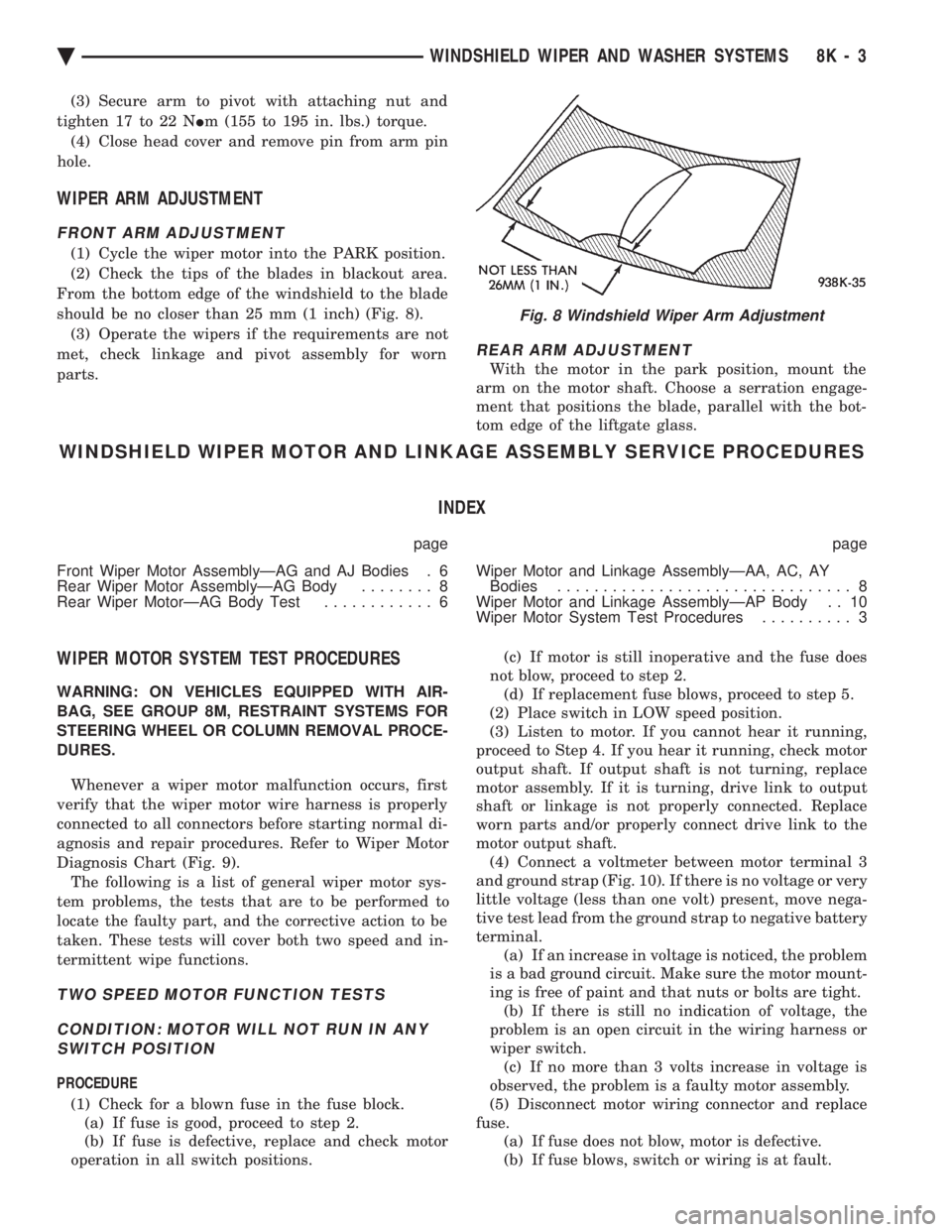
(2) Check the tips of the blades in blackout area.
From the bottom edge of the windshield to the blade
should be no closer than 25 mm (1 inch) (Fig. 8). (3) Operate the wipers if the requirements are not
met, check linkage and pivot assembly for worn
parts.
REAR ARM ADJUSTMENT
With the motor in the park position, mount the
arm on the motor shaft. Choose a serration engage-
ment that positions the blade, parallel with the bot-
tom edge of the liftgate glass.
WINDSHIELD WIPER MOTOR AND LINKAGE ASSEMBLY SERVICE PROCEDURES
INDEX
page page
Front Wiper Motor AssemblyÐAG and AJ Bodies . 6
Rear Wiper Motor AssemblyÐAG Body ........ 8
Rear Wiper MotorÐAG Body Test ............ 6 Wiper Motor and Linkage AssemblyÐAA, AC, AY
Bodies ................................ 8
Wiper Motor and Linkage AssemblyÐAP Body . . 10
Wiper Motor System Test Procedures .......... 3
WIPER MOTOR SYSTEM TEST PROCEDURES
WARNING: ON VEHICLES EQUIPPED WITH AIR-
BAG, SEE GROUP 8M, RESTRAINT SYSTEMS FOR
STEERING WHEEL OR COLUMN REMOVAL PROCE-
DURES.
Whenever a wiper motor malfunction occurs, first
verify that the wiper motor wire harness is properly
connected to all connectors before starting normal di-
agnosis and repair procedures. Refer to Wiper Motor
Diagnosis Chart (Fig. 9). The following is a list of general wiper motor sys-
tem problems, the tests that are to be performed to
locate the faulty part, and the corrective action to be
taken. These tests will cover both two speed and in-
termittent wipe functions.
TWO SPEED MOTOR FUNCTION TESTS
CONDITION: MOTOR WILL NOT RUN IN ANY SWITCH POSITION
PROCEDURE
(1) Check for a blown fuse in the fuse block. (a) If fuse is good, proceed to step 2.
(b) If fuse is defective, replace and check motor
operation in all switch positions. (c) If motor is still inoperative and the fuse does
not blow, proceed to step 2. (d) If replacement fuse blows, proceed to step 5.
(2) Place switch in LOW speed position.
(3) Listen to motor. If you cannot hear it running,
proceed to Step 4. If you hear it running, check motor
output shaft. If output shaft is not turning, replace
motor assembly. If it is turning, drive link to output
shaft or linkage is not properly connected. Replace
worn parts and/or properly connect drive link to the
motor output shaft. (4) Connect a voltmeter between motor terminal 3
and ground strap (Fig. 10). If there is no voltage or very
little voltage (less than one volt) present, move nega-
tive test lead from the ground strap to negative battery
terminal. (a) If an increase in voltage is noticed, the problem
is a bad ground circuit. Make sure the motor mount-
ing is free of paint and that nuts or bolts are tight. (b) If there is still no indication of voltage, the
problem is an open circuit in the wiring harness or
wiper switch. (c) If no more than 3 volts increase in voltage is
observed, the problem is a faulty motor assembly.
(5) Disconnect motor wiring connector and replace
fuse. (a) If fuse does not blow, motor is defective.
(b) If fuse blows, switch or wiring is at fault.
Fig. 8 Windshield Wiper Arm Adjustment
Ä WINDSHIELD WIPER AND WASHER SYSTEMS 8K - 3
Page 632 of 2438
INTERMITTENT WINDSHIELD WIPER MOTOR AND SWITCH SERVICE PROCEDURES
INDEX
page page
Intermittent Windshield Wiper Switch Tests ..... 12
Intermittent Wipe Switch Test ............... 14
Intermittent Wiper Function Tests ............ 14
Intermittent Wiper Motor System Test ......... 12 Pulse Intermittent Windshield Wiper Controller
(PIWWC) .............................. 15
Standard Wiper Switch Test ................ 14
Wiper Switch Service Procedure ............. 15
INTERMITTENT WIPER MOTOR SYSTEM TEST
Intermittent Wiper Motor Service Procedures for
diagnosis of problems which do not involve the delay
function, refer to the Two-Speed Motor Function
Tests. The two-speed functions of all wiper motors
are identical. If a problem occurs, only in the DELAY mode, the
following tests are to be performed.
INTERMITTENT WINDSHIELD WIPER SWITCH
TESTS
WARNING: ON VEHICLES EQUIPPED WITH AIR-
BAG, SEE GROUP 8M, RESTRAINT SYSTEMS FOR
STEERING WHEEL OR COLUMN REMOVAL PROCE-
DURES.
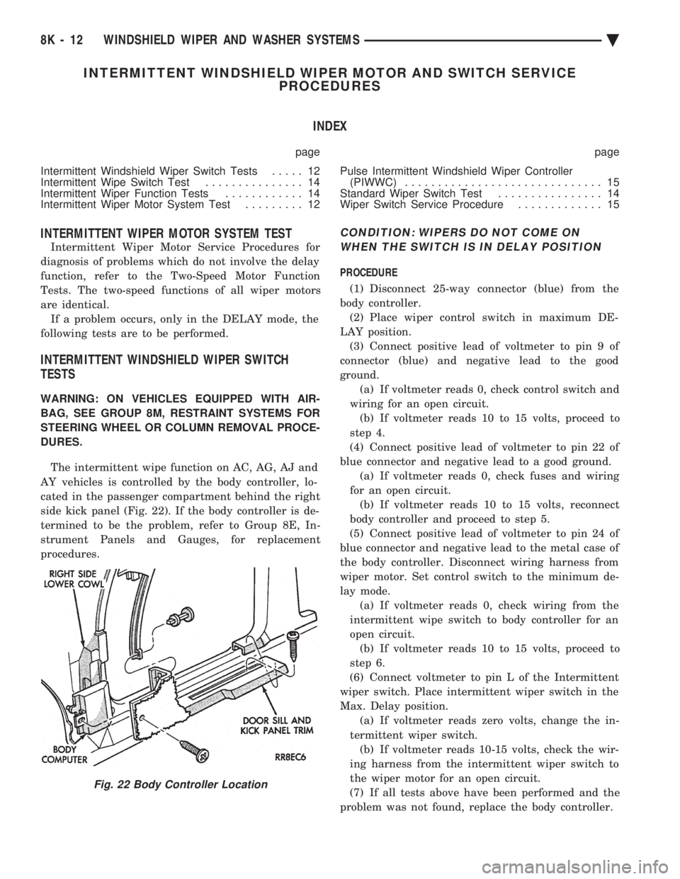
The intermittent wipe function on AC, AG, AJ and
AY vehicles is controlled by the body controller, lo-
cated in the passenger compartment behind the right
side kick panel (Fig. 22). If the body controller is de-
termined to be the problem, refer to Group 8E, In-
strument Panels and Gauges, for replacement
procedures.
CONDITION: WIPERS DO NOT COME ON WHEN THE SWITCH IS IN DELAY POSITION
PROCEDURE
(1) Disconnect 25-way connector (blue) from the
body controller. (2) Place wiper control switch in maximum DE-
LAY position. (3) Connect positive lead of voltmeter to pin 9 of
connector (blue) and negative lead to the good
ground. (a) If voltmeter reads 0, check control switch and
wiring for an open circuit. (b) If voltmeter reads 10 to 15 volts, proceed to
step 4.
(4) Connect positive lead of voltmeter to pin 22 of
blue connector and negative lead to a good ground. (a) If voltmeter reads 0, check fuses and wiring
for an open circuit. (b) If voltmeter reads 10 to 15 volts, reconnect
body controller and proceed to step 5.
(5) Connect positive lead of voltmeter to pin 24 of
blue connector and negative lead to the metal case of
the body controller. Disconnect wiring harness from
wiper motor. Set control switch to the minimum de-
lay mode. (a) If voltmeter reads 0, check wiring from the
intermittent wipe switch to body controller for an
open circuit. (b) If voltmeter reads 10 to 15 volts, proceed to
step 6.
(6) Connect voltmeter to pin L of the Intermittent
wiper switch. Place intermittent wiper switch in the
Max. Delay position. (a) If voltmeter reads zero volts, change the in-
termittent wiper switch. (b) If voltmeter reads 10-15 volts, check the wir-
ing harness from the intermittent wiper switch to
the wiper motor for an open circuit.
(7) If all tests above have been performed and the
problem was not found, replace the body controller.
Fig. 22 Body Controller Location
8K - 12 WINDSHIELD WIPER AND WASHER SYSTEMS Ä
Page 635 of 2438
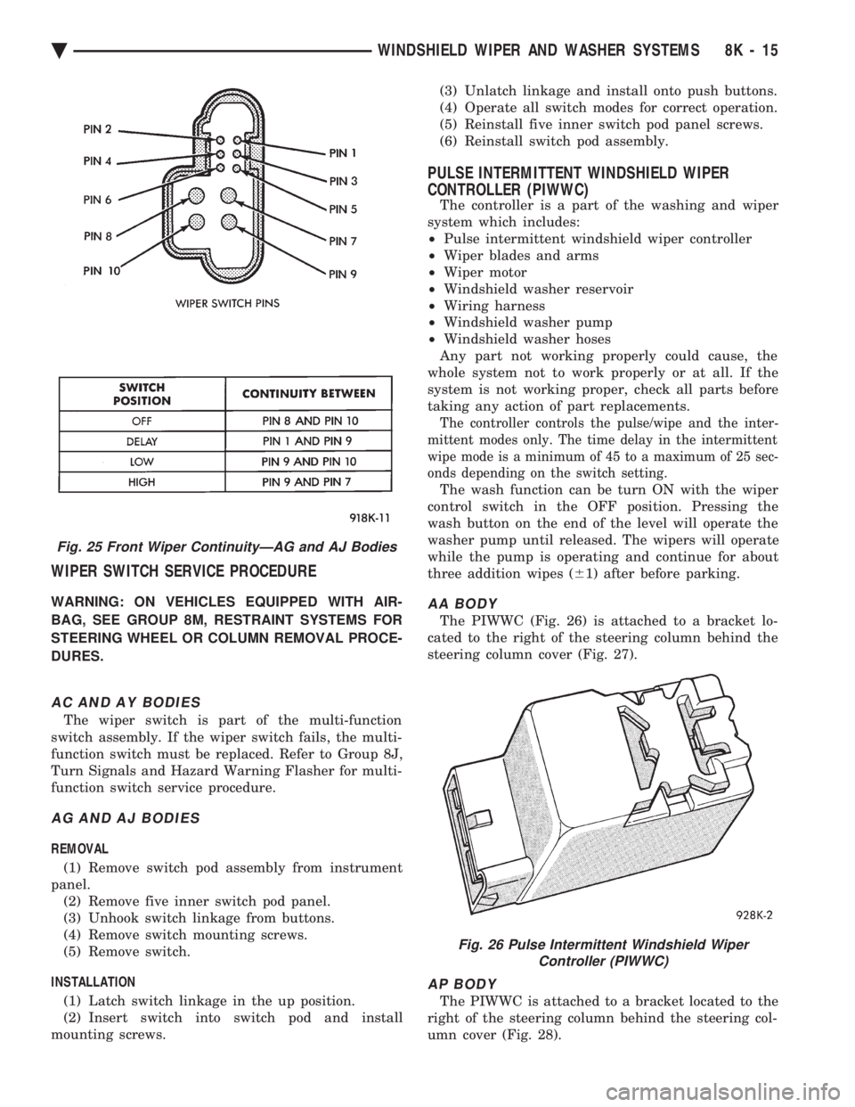
WIPER SWITCH SERVICE PROCEDURE
WARNING: ON VEHICLES EQUIPPED WITH AIR-
BAG, SEE GROUP 8M, RESTRAINT SYSTEMS FOR
STEERING WHEEL OR COLUMN REMOVAL PROCE-
DURES.
AC AND AY BODIES
The wiper switch is part of the multi-function
switch assembly. If the wiper switch fails, the multi-
function switch must be replaced. Refer to Group 8J,
Turn Signals and Hazard Warning Flasher for multi-
function switch service procedure.
AG AND AJ BODIES
REMOVAL
(1) Remove switch pod assembly from instrument
panel. (2) Remove five inner switch pod panel.
(3) Unhook switch linkage from buttons.
(4) Remove switch mounting screws.
(5) Remove switch.
INSTALLATION (1) Latch switch linkage in the up position.
(2) Insert switch into switch pod and install
mounting screws. (3) Unlatch linkage and install onto push buttons.
(4) Operate all switch modes for correct operation.
(5) Reinstall five inner switch pod panel screws.
(6) Reinstall switch pod assembly.
PULSE INTERMITTENT WINDSHIELD WIPER
CONTROLLER (PIWWC)
The controller is a part of the washing and wiper
system which includes:
² Pulse intermittent windshield wiper controller
² Wiper blades and arms
² Wiper motor
² Windshield washer reservoir
² Wiring harness
² Windshield washer pump
² Windshield washer hoses
Any part not working properly could cause, the
whole system not to work properly or at all. If the
system is not working proper, check all parts before
taking any action of part replacements.
The controller controls the pulse/wipe and the inter-
mittent modes only. The time delay in the intermittent
wipe mode is a minimum of 45 to a maximum of 25 sec-
onds depending on the switch setting.
The wash function can be turn ON with the wiper
control switch in the OFF position. Pressing the
wash button on the end of the level will operate the
washer pump until released. The wipers will operate
while the pump is operating and continue for about
three addition wipes ( 61) after before parking.
AA BODY
The PIWWC (Fig. 26) is attached to a bracket lo-
cated to the right of the steering column behind the
steering column cover (Fig. 27).
AP BODY
The PIWWC is attached to a bracket located to the
right of the steering column behind the steering col-
umn cover (Fig. 28).
Fig. 25 Front Wiper ContinuityÐAG and AJ Bodies
Fig. 26 Pulse Intermittent Windshield Wiper Controller (PIWWC)
Ä WINDSHIELD WIPER AND WASHER SYSTEMS 8K - 15
Page 637 of 2438
WINDSHIELD WASHERS INDEX
page page
General Information ....................... 17
Washer Nozzle .......................... 19 Washer Reservoir Pump
................... 18
Washer Reservoirs ....................... 17
GENERAL INFORMATION
All models are equipped with electric operated
windshield washer pumps. The wash function can be accessed in the OFF po-
sition of the wiper control switch. Holding the wash
button depressed when the switch is in the OFF po-
sition will operate the wipers and washer motor
pump continuously until the washer button is re-
leased. Releasing the button will stop the washer
pump but the wipers will complete the current wipe
cycle. Then followed by an average of two more wipe
cycles ( 61) before the wipers park and the module
turns off. Whenever a windshield washer malfunction occurs,
first verify that the windshield washer wire harness
is properly connected to all connectors before starting
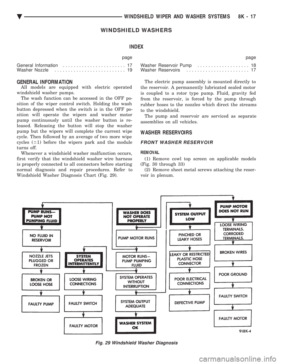
normal diagnosis and repair procedures. Refer to
Windshield Washer Diagnosis Chart (Fig. 29). The electric pump assembly is mounted directly to
the reservoir. A permanently lubricated sealed motor
is coupled to a rotor type pump. Fluid, gravity fed
from the reservoir, is forced by the pump through
rubber hoses to the nozzles which direct the streams
to the windshield. The pump and reservoir are serviced as separate
assemblies on all vehicles.
WASHER RESERVOIRS
FRONT WASHER RESERVOIR
REMOVAL
(1) Remove cowl top screen on applicable models
(Fig. 30 through 33) (2) Remove sheet metal screws attaching the reser-
voir in plenum.
Fig. 29 Windshield Washer Diagnosis
Ä WINDSHIELD WIPER AND WASHER SYSTEMS 8K - 17
Page 643 of 2438
LAMPS
CONTENTS
page page
BULB APPLICATION TABLE ............... 38
CONCEALED HEADLAMPS ................ 27
EXTERIOR LAMP SWITCHES AND HEADLAMP ALIGNMENT ........................... 3
EXTERIOR LAMP SYSTEMS .............. 25
EXTERIOR LAMPSÐAA BODY ............. 7
EXTERIOR LAMPSÐAC BODY ............ 10 EXTERIOR LAMPSÐAG BODY
............ 14
EXTERIOR LAMPSÐAJ BODY ............ 16
EXTERIOR LAMPSÐAP BODY ............ 19
EXTERIOR LAMPSÐAY-BODY ............ 22
GENERAL INFORMATION .................. 1
ILLUMINATED ENTRY SYSTEM ........... 33
GENERAL INFORMATION
Each vehicle is equipped with lamps used for illumi-
nating and indicating purposes. A circuit must have a
good ground to be complete. Circuit ground occurs
when the lamp socket makes contact with the metal
body. On vehicles with plastic lamps, a wire between
the socket and the body makes the grounds. When changing lamp bulbs, check the socket for
corrosion. If corrosion is present, clean contacts with a
wire brush and coat the inside of the socket with
Mopar tMulti-purpose Grease or equivalent.
CAUTION: Do not touch the glass of halogen bulbs
with fingers or any possibly oily surface, reduced
bulb life will result.
BODY IDENTIFICATION
Throughout this Group, references are made to the
vehicle family or body code. To decode the vehicle
identification plates, refer to the Introduction Section
at the front of this manual.
DIAGNOSTIC PROCEDURES
Begin electrical system failure diagnosis by testing
all related fuses and circuit breakers in the fuse block
and engine compartment. When a vehicle experiences problems with the head-
lamp system, verify the condition of the battery con-
nections, charging system, headlamp bulbs, wire con-
nectors, relay, high beam dimmer switch and headlamp
switch. Refer to Wiring Diagrams manual for compo-
nent locations and circuit information.
SYMPTOM
Headlamps are dim when engine is idling of
with ignition turned OFF. Canada cars must
have lamps ON. ACTION
² Clean battery terminal clamps and posts. Refer to
Group 8B, Battery/Starter/Generator Service for
proper procedures.
² Test charging system output. Refer to Group 8A,
Battery/Starting/Charging Systems Diagnostics for
proper testing procedures.
² Test for high resistance in headlamp circuits.
² Defective headlamp bulb.
SYMPTOM
Bulbs burn out frequently.
ACTION
² Test charging system output. Refer to Group 8A,
Battery/Starting/Charging Systems Diagnostics for
proper testing procedures.
² Check for loose or corroded connector terminals or
splices in headlamp circuits. Refer to Wiring Diagrams
manual for component and splice locations.
SYMPTOM
Headlamps are dim with engine running above
idle. Canada cars must have lamps ON.
ACTION
² Test charging system output. Refer to Group 8A,
Battery/Starting/Charging Systems Diagnostics for
proper testing procedures.
² Test for high resistance in headlamp circuits.
² Defective headlamp bulb.
SYMPTOM
Headlamps flash randomly.
ACTION
² Test for poor circuit ground.
² Test for high resistance in headlamp circuits.
Ä LAMPS 8L - 1