1993 CHEVROLET DYNASTY service
[x] Cancel search: servicePage 1654 of 2438
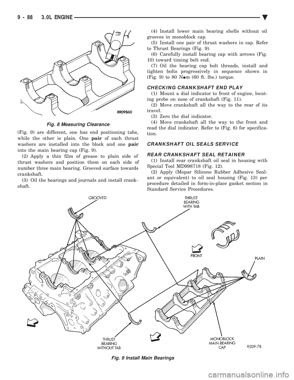
(Fig. 9) are different, one has end positioning tabs,
while the other is plain. One pairof each thrust
washers are installed into the block and one pair
into the main bearing cap (Fig. 9). (2) Apply a thin film of grease to plain side of
thrust washers and position them on each side of
number three main bearing. Grooved surface towards
crankshaft. (3) Oil the bearings and journals and install crank-
shaft. (4) Install lower main bearing shells without oil
grooves in monoblock cap. (5) Install one pair of thrust washers in cap. Refer
to Thrust Bearings (Fig. 9). (6) Carefully install bearing cap with arrows (Fig.
10) toward timing belt end. (7) Oil the bearing cap bolt threads, install and
tighten bolts progressively in sequence shown in
(Fig. 9) to 80 N Im (60 ft. lbs.) torque.
CHECKING CRANKSHAFT END PLAY
(1) Mount a dial indicator to front of engine, locat-
ing probe on nose of crankshaft (Fig. 11). (2) Move crankshaft all the way to the rear of its
travel. (3) Zero the dial indicator.
(4) Move crankshaft all the way to the front and
read the dial indicator. Refer to (Fig. 6) for specifica-
tion.
CRANKSHAFT OIL SEALS SERVICE
REAR CRANKSHAFT SEAL RETAINER
(1) Install rear crankshaft oil seal in housing with
Special Tool MD998718 (Fig. 12). (2) Apply (Mopar Silicone Rubber Adhesive Seal-
ant or equivalent) to oil seal housing (Fig. 13) per
procedure detailed in form-in-place gasket section in
Standard Service Procedures.
Fig. 9 Install Main Bearings
Fig. 8 Measuring Clearance
9 - 88 3.0L ENGINE Ä
Page 1656 of 2438
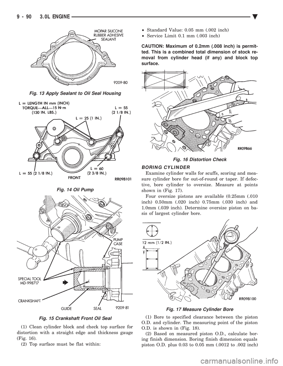
(1) Clean cylinder block and check top surface for
distortion with a straight edge and thickness gauge
(Fig. 16). (2) Top surface must be flat within: ²
Standard Value: 0.05 mm (.002 inch)
² Service Limit 0.1 mm (.003 inch)
CAUTION: Maximum of 0.2mm (.008 inch) is permit-
ted. This is a combined total dimension of stock re-
moval from cylinder head (if any) and block top
surface.
BORING CYLINDER
Examine cylinder walls for scuffs, scoring and mea-
sure cylinder bore for out-of-round or taper. If defec-
tive, bore cylinder to oversize. Measure at points
shown in (Fig. 17). Four oversize pistons are available (0.25mm (.010
inch) 0.50mm (.020 inch) 0.75mm (.030 inch) and
1.0mm (.039 inch). Determine oversize piston on ba-
sis of largest cylinder bore.
(1) Bore to specified clearance between the piston
O.D. and cylinder. The measuring point of the piston
O.D. is shown in (Fig. 18). (2) Based on measured piston O.D., calculate bor-
ing finish dimension. Boring finish dimension equals
piston O.D. plus 0.03 to 0.05 mm (.0012 to .002 inch)
Fig. 13 Apply Sealant to Oil Seal Housing
Fig. 14 Oil Pump
Fig. 15 Crankshaft Front Oil Seal
Fig. 16 Distortion Check
Fig. 17 Measure Cylinder Bore
9 - 90 3.0L ENGINE Ä
Page 1658 of 2438
OIL PAN
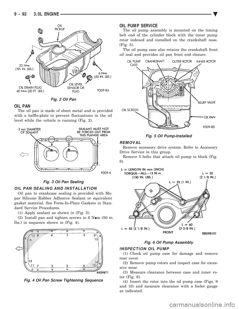
The oil pan is made of sheet metal and is provided
with a baffle-plate to prevent fluctuations in the oil
level while the vehicle is running (Fig. 2).
OIL PAN SEALING AND INSTALLATION
Oil pan to crankcase sealing is provided with Mo-
par Silicone Rubber Adhesive Sealant or equivalent
gasket material. See Form-In-Place Gaskets in Stan-
dard Service Procedures. (1) Apply sealant as shown in (Fig. 3).
(2) Install pan and tighten screws to 6 N Im (50 in.
lbs.) in sequence shown in (Fig. 4).
OIL PUMP SERVICE
The oil pump assembly is mounted on the timing
belt end of the cylinder block with the inner pump
rotor indexed and installed on the crankshaft nose.
(Fig. 5). The oil pump case also retains the crankshaft front
oil seal and provides oil pan front end closure.
REMOVAL
Remove accessory drive system. Refer to Accessory
Drive Service in this group. Remove 5 bolts that attach oil pump to block (Fig.
6).
INSPECTION OIL PUMP
(1) Check oil pump case for damage and remove
rear cover. (2) Remove pump rotors and inspect case for exces-
sive wear. (3) Measure clearance between case and inner ro-
tor (Fig. 8). (4) Insert the rotor into the oil pump case (Figs. 9
and 10) and measure clearance with a feeler gauge
as indicated.
Fig. 2 Oil Pan
Fig. 3 Oil Pan Sealing
Fig. 4 Oil Pan Screw Tightening Sequence
Fig. 5 Oil Pump-Installed
Fig. 6 Oil Pump Assembly
9 - 92 3.0L ENGINE Ä
Page 1664 of 2438
3.3/3.8L ENGINE INDEX
page page
Camshaft .............................. 112
Camshaft BearingsÐEngine Removed From Vehicle .............................. 113
Checking Engine Oil Pressure .............. 125
Connecting Rods ........................ 118
Crankshaft Oil Seals Service ............... 121
Crankshaft Service ...................... 118
Cylinder Block, Piston and Connecting Rod Assembly Service ...................... 114
Cylinder Heads ......................... 102
Engine Assembly ........................ 101
Engine Core Oil and Cam Plugs ............ 113
Engine Lubrication System ................ 122 Engine Mounts
.......................... 99
Engine Specifications ..................... 126
General Information ....................... 98
Hydraulic Tappets ....................... 108
Installing Piston and Connecting Rod Assembly . 117
Intake Manifold Sealing ................... 104
Oil Filter .............................. 125
Oil Pan Service ......................... 122
Oil Pump Service ....................... 123
Rocker Arms and Shaft Assembly ........... 102
Timing Chain Cover, Oil Seal and Chain ...... 109
Valve Service .......................... 104
Valve Timing ........................... 109
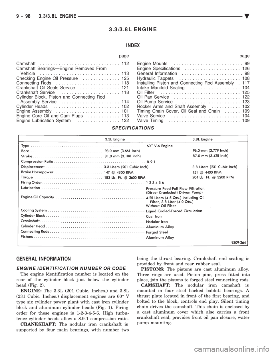
GENERAL INFORMATION
ENGINE IDENTIFICATION NUMBER OR CODE
The engine identification number is located on the
rear of the cylinder block just below the cylinder
head (Fig. 2). ENGINE: The 3.3L (201 Cubic. Inches.) and 3.8L
(231 Cubic. Inches.) displacement engines are 60É V
type six cylinder power plant with cast iron cylinder
block and aluminum cylinder heads (Fig. 1). Firing
order for these engines is 1-2-3-4-5-6. High turbu-
lence cylinder heads allow a 8.9-1 compression ratio. CRANKSHAFT: The nodular iron crankshaft is
supported by four main bearings, with number two being the thrust bearing. Crankshaft end sealing is
provided by front and rear rubber seal. PISTONS: The pistons are cast aluminum alloy.
Three rings are used. Piston pins, press fitted into
place, join the pistons to forged steel connecting rods. CAMSHAFT: The nodular iron camshaft is
mounted in four steel backed babbitt bearings. A
thrust plate located in front of the first bearing, and
bolted to the block, controls end play. Silent timing
chain drives the camshaft. This chain is enclosed by
a cast aluminum cover which also carries a front
crankshaft seal, provides front oil pan closure, water
pump mounting.
SPECIFICATIONS
9 - 98 3.3/3.8L ENGINE Ä
Page 1670 of 2438
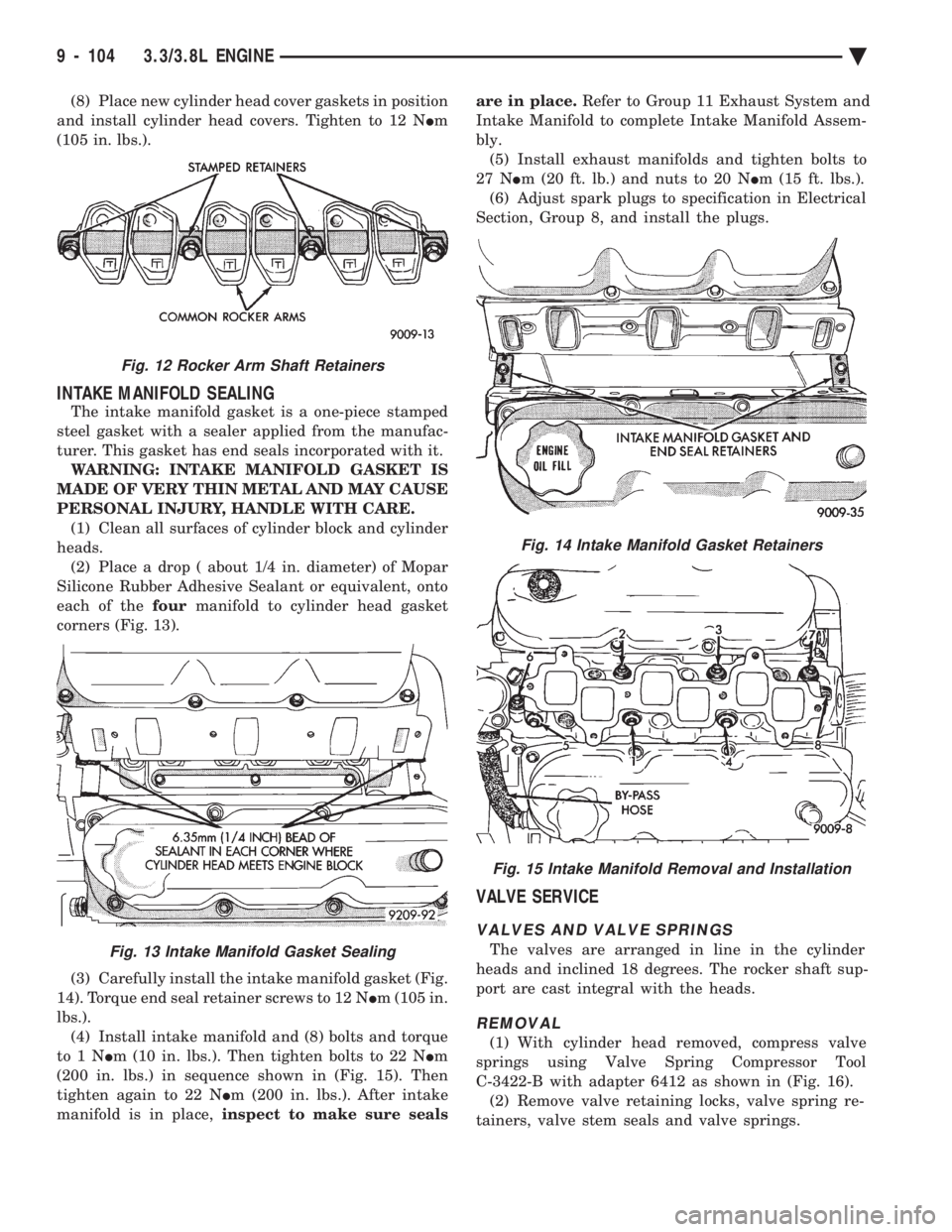
(8) Place new cylinder head cover gaskets in position
and install cylinder head covers. Tighten to 12 N Im
(105 in. lbs.).
INTAKE MANIFOLD SEALING
The intake manifold gasket is a one-piece stamped
steel gasket with a sealer applied from the manufac-
turer. This gasket has end seals incorporated with it. WARNING: INTAKE MANIFOLD GASKET IS
MADE OF VERY THIN METAL AND MAY CAUSE
PERSONAL INJURY, HANDLE WITH CARE. (1) Clean all surfaces of cylinder block and cylinder
heads. (2) Place a drop ( about 1/4 in. diameter) of Mopar
Silicone Rubber Adhesive Sealant or equivalent, onto
each of the fourmanifold to cylinder head gasket
corners (Fig. 13).
(3) Carefully install the intake manifold gasket (Fig.
14). Torque end seal retainer screws to 12 N Im (105 in.
lbs.). (4) Install intake manifold and (8) bolts and torque
to1N Im (10 in. lbs.). Then tighten bolts to 22 N Im
(200 in. lbs.) in sequence shown in (Fig. 15). Then
tighten again to 22 N Im (200 in. lbs.). After intake
manifold is in place, inspect to make sure seals are in place.
Refer to Group 11 Exhaust System and
Intake Manifold to complete Intake Manifold Assem-
bly. (5) Install exhaust manifolds and tighten bolts to
27 N Im (20 ft. lb.) and nuts to 20 N Im (15 ft. lbs.).
(6) Adjust spark plugs to specification in Electrical
Section, Group 8, and install the plugs.
VALVE SERVICE
VALVES AND VALVE SPRINGS
The valves are arranged in line in the cylinder
heads and inclined 18 degrees. The rocker shaft sup-
port are cast integral with the heads.
REMOVAL
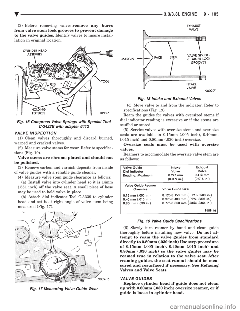
(1) With cylinder head removed, compress valve
springs using Valve Spring Compressor Tool
C-3422-B with adapter 6412 as shown in (Fig. 16). (2) Remove valve retaining locks, valve spring re-
tainers, valve stem seals and valve springs.
Fig. 14 Intake Manifold Gasket Retainers
Fig. 15 Intake Manifold Removal and Installation
Fig. 12 Rocker Arm Shaft Retainers
Fig. 13 Intake Manifold Gasket Sealing
9 - 104 3.3/3.8L ENGINE Ä
Page 1671 of 2438
(3) Before removing valves, remove any burrs
from valve stem lock grooves to prevent damage
to the valve guides. Identify valves to insure instal-
lation in original location.
VALVE INSPECTION
(1) Clean valves thoroughly and discard burned,
warped and cracked valves. (2) Measure valve stems for wear. Refer to specifica-
tions (Fig. 19). Valve stems are chrome plated and should not
be polished. (3) Remove carbon and varnish deposits from inside
of valve guides with a reliable guide cleaner. (4) Measure valve stem guide clearance as follows:(a) Install valve into cylinder head so it is 14mm
(.551 inch) off the valve seat. A small piece of hose
may be used to hold valve in place. (b) Attach dial indicator Tool C-3339 to cylinder
head and set it at right angle of valve stem being
measured (Fig. 17). (c) Move valve to and from the indicator. Refer to
specifications (Fig. 19).
Ream the guides for valves with oversized stems if
dial indicator reading is excessive or if the stems are
scuffed or scored. (5) Service valves with oversize stems and over size
seals are available in 0.15mm (.005 inch), 0.40mm,
(.015 inch) and 0.80mm (.030 inch) oversize. Oversize seals must be used with oversize
valves. Reamers to accommodate the oversize valve stem are
as follows:
(6) Slowly turn reamer by hand and clean guide
thoroughly before installing new valve. Do not at-
tempt to ream the valve guides from standard
directly to 0.80mm (.030 inch) Use step procedure
of 0.15mm (.005 inch), 0.40mm (.015 inch) and
0.80mm (.030 inch) so the valve guides may be
reamed true in relation to the valve seat. After
reaming guides, the seat runout should be mea-
sured and resurfaced if necessary. See Refacing
Valves and Valve Seats.
VALVE GUIDES
Replace cylinder head if guide does not clean
up with 0.80mm (.030 inch) oversize reamer, or if
guide is loose in cylinder head.
Fig. 18 Intake and Exhaust Valves
Fig. 19 Valve Guide Specifications
Fig. 16 Compress Valve Springs with Special Tool C-3422B with adapter 6412
Fig. 17 Measuring Valve Guide Wear
Ä 3.3/3.8L ENGINE 9 - 105
Page 1674 of 2438
(15) Install rocker arm covers tighten screws to 14
N Im (120 in. lbs.) and connector to ignition coils.
(16) Install Intake Manifold; Refer to Intake Mani-
fold Installation 3.3/3.8L Engine, Group 11 Exhaust
System and Intake Manifold.
HYDRAULIC TAPPETS
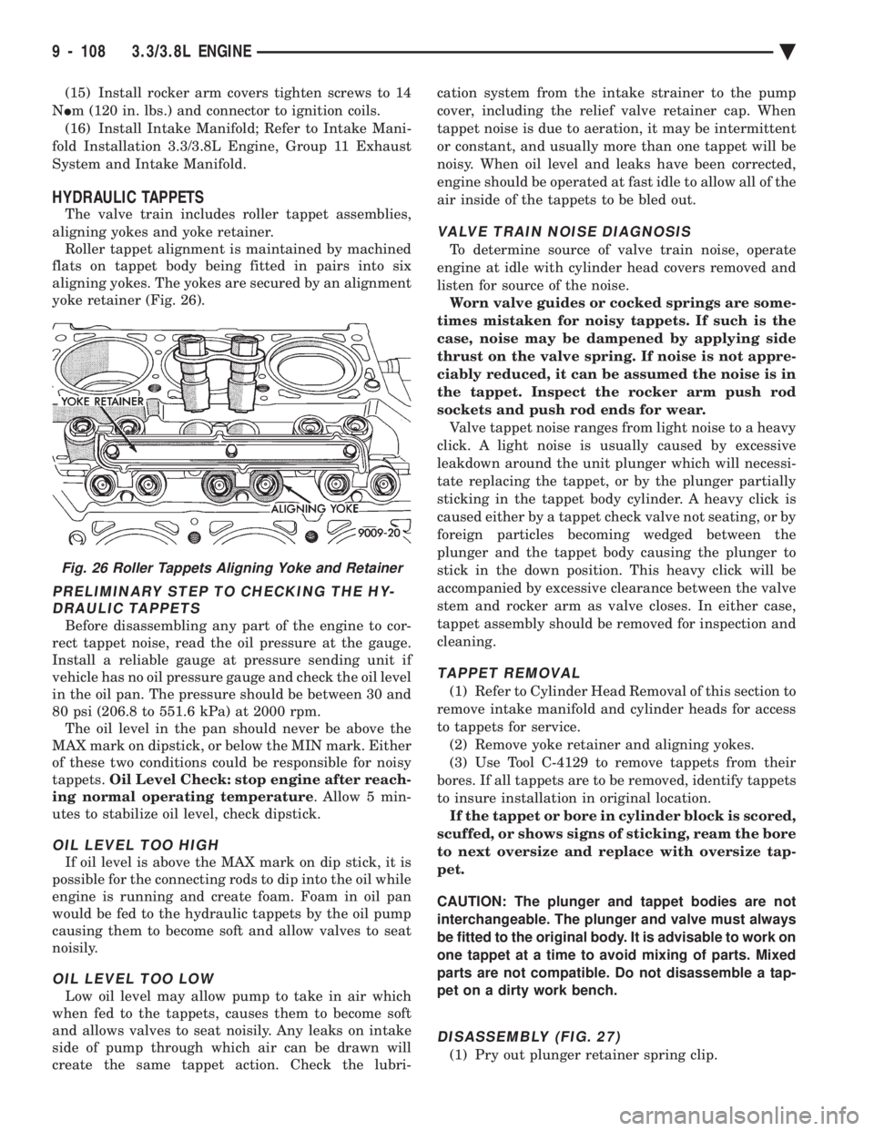
The valve train includes roller tappet assemblies,
aligning yokes and yoke retainer. Roller tappet alignment is maintained by machined
flats on tappet body being fitted in pairs into six
aligning yokes. The yokes are secured by an alignment
yoke retainer (Fig. 26).
PRELIMINARY STEP TO CHECKING THE HY- DRAULIC TAPPETS
Before disassembling any part of the engine to cor-
rect tappet noise, read the oil pressure at the gauge.
Install a reliable gauge at pressure sending unit if
vehicle has no oil pressure gauge and check the oil level
in the oil pan. The pressure should be between 30 and
80 psi (206.8 to 551.6 kPa) at 2000 rpm. The oil level in the pan should never be above the
MAX mark on dipstick, or below the MIN mark. Either
of these two conditions could be responsible for noisy
tappets. Oil Level Check: stop engine after reach-
ing normal operating temperature . Allow 5 min-
utes to stabilize oil level, check dipstick.
OIL LEVEL TOO HIGH
If oil level is above the MAX mark on dip stick, it is
possible for the connecting rods to dip into the oil while
engine is running and create foam. Foam in oil pan
would be fed to the hydraulic tappets by the oil pump
causing them to become soft and allow valves to seat
noisily.
OIL LEVEL TOO LOW
Low oil level may allow pump to take in air which
when fed to the tappets, causes them to become soft
and allows valves to seat noisily. Any leaks on intake
side of pump through which air can be drawn will
create the same tappet action. Check the lubri- cation system from the intake strainer to the pump
cover, including the relief valve retainer cap. When
tappet noise is due to aeration, it may be intermittent
or constant, and usually more than one tappet will be
noisy. When oil level and leaks have been corrected,
engine should be operated at fast idle to allow all of the
air inside of the tappets to be bled out.
VALVE TRAIN NOISE DIAGNOSIS
To determine source of valve train noise, operate
engine at idle with cylinder head covers removed and
listen for source of the noise. Worn valve guides or cocked springs are some-
times mistaken for noisy tappets. If such is the
case, noise may be dampened by applying side
thrust on the valve spring. If noise is not appre-
ciably reduced, it can be assumed the noise is in
the tappet. Inspect the rocker arm push rod
sockets and push rod ends for wear. Valve tappet noise ranges from light noise to a heavy
click. A light noise is usually caused by excessive
leakdown around the unit plunger which will necessi-
tate replacing the tappet, or by the plunger partially
sticking in the tappet body cylinder. A heavy click is
caused either by a tappet check valve not seating, or by
foreign particles becoming wedged between the
plunger and the tappet body causing the plunger to
stick in the down position. This heavy click will be
accompanied by excessive clearance between the valve
stem and rocker arm as valve closes. In either case,
tappet assembly should be removed for inspection and
cleaning.
TAPPET REMOVAL
(1) Refer to Cylinder Head Removal of this section to
remove intake manifold and cylinder heads for access
to tappets for service. (2) Remove yoke retainer and aligning yokes.
(3) Use Tool C-4129 to remove tappets from their
bores. If all tappets are to be removed, identify tappets
to insure installation in original location. If the tappet or bore in cylinder block is scored,
scuffed, or shows signs of sticking, ream the bore
to next oversize and replace with oversize tap-
pet.
CAUTION: The plunger and tappet bodies are not
interchangeable. The plunger and valve must always
be fitted to the original body. It is advisable to work on
one tappet at a time to avoid mixing of parts. Mixed
parts are not compatible. Do not disassemble a tap-
pet on a dirty work bench.
DISASSEMBLY (FIG. 27)
(1) Pry out plunger retainer spring clip.
Fig. 26 Roller Tappets Aligning Yoke and Retainer
9 - 108 3.3/3.8L ENGINE Ä
Page 1679 of 2438
(9) Measure camshaft end play. End Play should
measure .0127 to .304 mm (.005 to .012 inches.) .310
mm (.012 inch. Max.). If not within limits install a new
thrust plate. (10) Each tappet reused must be installed in the
same position from which it was removed. When
camshaft is replaced, all of the tappets must be
replaced .
CAMSHAFT BEARINGSÐENGINE REMOVED FROM
VEHICLE
REMOVAL
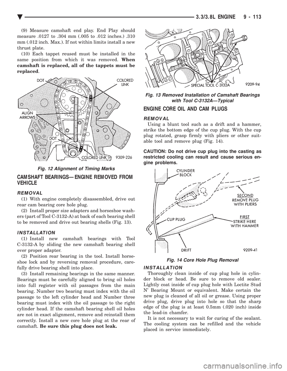
(1) With engine completely disassembled, drive out
rear cam bearing core hole plug. (2) Install proper size adapters and horseshoe wash-
ers (part of Tool C-3132-A) at back of each bearing shell
to be removed and drive out bearing shells (Fig. 13).
INSTALLATION
(1) Install new camshaft bearings with Tool
C-3132-A by sliding the new camshaft bearing shell
over proper adapter. (2) Position rear bearing in the tool. Install horse-
shoe lock and by reversing removal procedure, care-
fully drive bearing shell into place. (3) Install remaining bearings in the same manner.
Bearings must be carefully aligned to bring oil holes
into full register with oil passages from the main
bearing. Number two bearing must index with the oil
passage to the left cylinder head and Number three
bearing must index with the oil passage to the right
cylinder head. If the camshaft bearing shell oil holes
are not in exact alignment, remove and reinstall them
correctly. Install a new core hole plug at the rear of
camshaft. Be sure this plug does not leak.
ENGINE CORE OIL AND CAM PLUGS
REMOVAL
Using a blunt tool such as a drift and a hammer,
strike the bottom edge of the cup plug. With the cup
plug rotated, grasp firmly with pliers or other suit-
able tool and remove plug (Fig. 14).
CAUTION: Do not drive cup plug into the casting as
restricted cooling can result and cause serious en-
gine problems.
INSTALLATION
Thoroughly clean inside of cup plug hole in cylin-
der block or head. Be sure to remove old sealer.
Lightly coat inside of cup plug hole with Loctite Stud
N' Bearing Mount or equivalent. Make certain the
new plug is cleaned of all oil or grease. Using proper
drive plug, drive plug into hole so that the sharp
edge of the plug is at least 0.5mm (.020 inch) inside
the lead-in chamfer. It is not necessary to wait for curing of the sealant.
The cooling system can be refilled and the vehicle
placed in service immediately.
Fig. 13 Removed Installation of Camshaft Bearings with Tool C-3132AÐTypical
Fig. 14 Core Hole Plug Removal
Fig. 12 Alignment of Timing Marks
Ä 3.3/3.8L ENGINE 9 - 113