1993 CHEVROLET DYNASTY wheel
[x] Cancel search: wheelPage 1728 of 2438
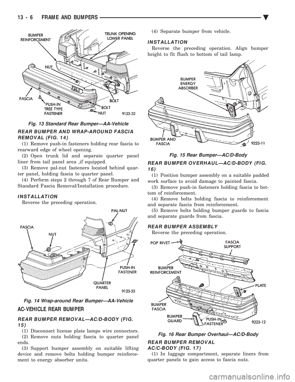
REAR BUMPER AND WRAP-AROUND FASCIA REMOVAL (FIG. 14)
(1) Remove push-in fasteners holding rear fascia to
rearward edge of wheel opening. (2) Open trunk lid and separate quarter panel
liner from tail panel area ,if equipped. (3) Remove pal-nut fasteners located behind quar-
ter panel, holding fascia to quarter panel. (4) Perform steps 2 through 7 of Rear Bumper and
Standard Fascia Removal/Installation procedure.
INSTALLATION
Reverse the preceding operation.
AC-VEHICLE REAR BUMPER
REAR BUMPER REMOVALÐAC/D-BODY (FIG. 15)
(1) Disconnect license plate lamps wire connectors.
(2) Remove nuts holding fascia to quarter panel
ends. (3) Support bumper assembly on suitable lifting
device and remove bolts holding bumper reinforce-
ment to energy absorber units. (4) Separate bumper from vehicle.
INSTALLATION
Reverse the preceding operation. Align bumper
height to fit flush to bottom of tail lamp.
REAR BUMPER OVERHAULÐAC/D-BODY (FIG. 16)
(1) Position bumper assembly on a suitable padded
work surface to avoid damage to painted fascia. (3) Remove push-in fasteners holding fascia to bot-
tom of reinforcement. (4) Remove bolts holding fascia to reinforcement
and separate fascia from reinforcement. (5) Remove bolts holding bumper guards to fascia
and separate guards from fascia.
REAR BUMPER ASSEMBLY
Reverse the preceding operation.
REAR BUMPER REMOVAL AC/C-BODY (FIG. 17)
(1) In luggage compartment, separate liners from
quarter panels to gain access to fascia nuts.
Fig. 13 Standard Rear BumperÐAA-Vehicle
Fig. 14 Wrap-around Rear BumperÐAA-Vehicle
Fig. 15 Rear BumperÐAC/D-Body
Fig. 16 Rear Bumper OverhaulÐAC/D-Body
13 - 6 FRAME AND BUMPERS Ä
Page 1729 of 2438
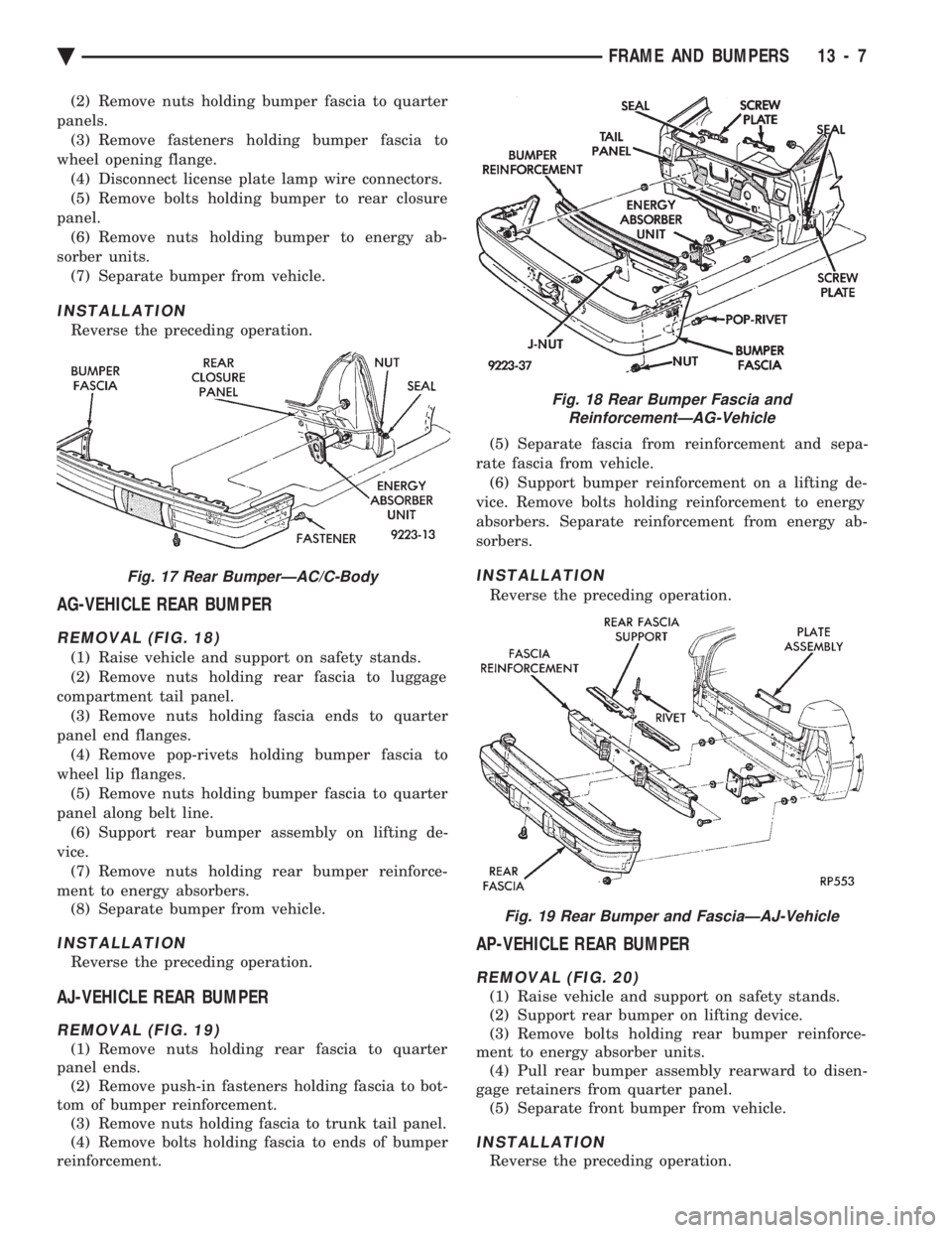
(2) Remove nuts holding bumper fascia to quarter
panels. (3) Remove fasteners holding bumper fascia to
wheel opening flange. (4) Disconnect license plate lamp wire connectors.
(5) Remove bolts holding bumper to rear closure
panel. (6) Remove nuts holding bumper to energy ab-
sorber units. (7) Separate bumper from vehicle.
INSTALLATION
Reverse the preceding operation.
AG-VEHICLE REAR BUMPER
REMOVAL (FIG. 18)
(1) Raise vehicle and support on safety stands.
(2) Remove nuts holding rear fascia to luggage
compartment tail panel. (3) Remove nuts holding fascia ends to quarter
panel end flanges. (4) Remove pop-rivets holding bumper fascia to
wheel lip flanges. (5) Remove nuts holding bumper fascia to quarter
panel along belt line. (6) Support rear bumper assembly on lifting de-
vice. (7) Remove nuts holding rear bumper reinforce-
ment to energy absorbers. (8) Separate bumper from vehicle.
INSTALLATION
Reverse the preceding operation.
AJ-VEHICLE REAR BUMPER
REMOVAL (FIG. 19)
(1) Remove nuts holding rear fascia to quarter
panel ends. (2) Remove push-in fasteners holding fascia to bot-
tom of bumper reinforcement. (3) Remove nuts holding fascia to trunk tail panel.
(4) Remove bolts holding fascia to ends of bumper
reinforcement. (5) Separate fascia from reinforcement and sepa-
rate fascia from vehicle. (6) Support bumper reinforcement on a lifting de-
vice. Remove bolts holding reinforcement to energy
absorbers. Separate reinforcement from energy ab-
sorbers.
INSTALLATION
Reverse the preceding operation.
AP-VEHICLE REAR BUMPER
REMOVAL (FIG. 20)
(1) Raise vehicle and support on safety stands.
(2) Support rear bumper on lifting device.
(3) Remove bolts holding rear bumper reinforce-
ment to energy absorber units. (4) Pull rear bumper assembly rearward to disen-
gage retainers from quarter panel. (5) Separate front bumper from vehicle.
INSTALLATION
Reverse the preceding operation.
Fig. 17 Rear BumperÐAC/C-Body
Fig. 18 Rear Bumper Fascia and ReinforcementÐAG-Vehicle
Fig. 19 Rear Bumper and FasciaÐAJ-Vehicle
Ä FRAME AND BUMPERS 13 - 7
Page 1730 of 2438
AY-VEHICLE REAR BUMPER
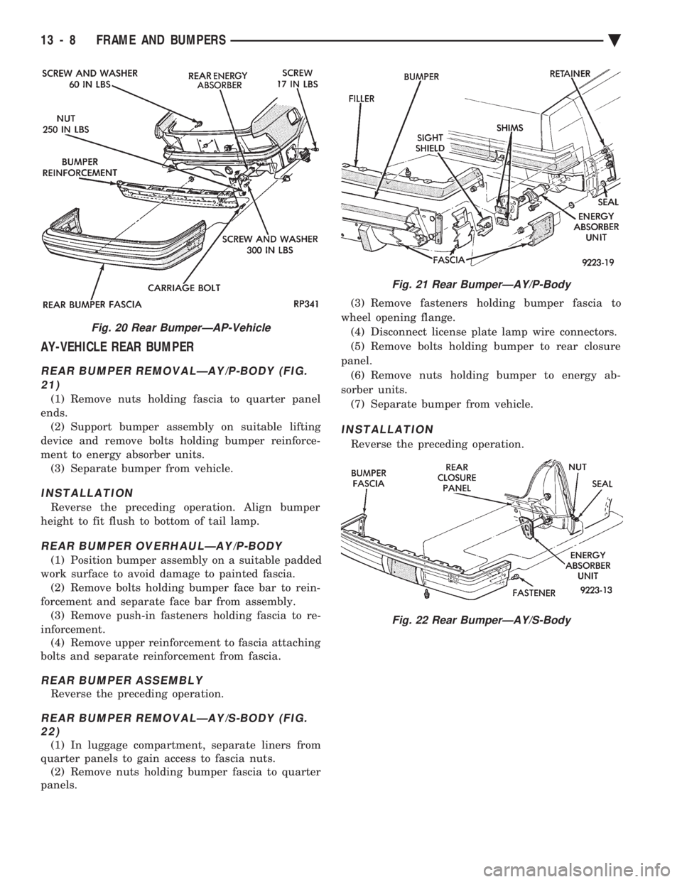
REAR BUMPER REMOVALÐAY/P-BODY (FIG. 21)
(1) Remove nuts holding fascia to quarter panel
ends. (2) Support bumper assembly on suitable lifting
device and remove bolts holding bumper reinforce-
ment to energy absorber units. (3) Separate bumper from vehicle.
INSTALLATION
Reverse the preceding operation. Align bumper
height to fit flush to bottom of tail lamp.
REAR BUMPER OVERHAULÐAY/P-BODY
(1) Position bumper assembly on a suitable padded
work surface to avoid damage to painted fascia. (2) Remove bolts holding bumper face bar to rein-
forcement and separate face bar from assembly. (3) Remove push-in fasteners holding fascia to re-
inforcement. (4) Remove upper reinforcement to fascia attaching
bolts and separate reinforcement from fascia.
REAR BUMPER ASSEMBLY
Reverse the preceding operation.
REAR BUMPER REMOVALÐAY/S-BODY (FIG. 22)
(1) In luggage compartment, separate liners from
quarter panels to gain access to fascia nuts. (2) Remove nuts holding bumper fascia to quarter
panels. (3) Remove fasteners holding bumper fascia to
wheel opening flange. (4) Disconnect license plate lamp wire connectors.
(5) Remove bolts holding bumper to rear closure
panel. (6) Remove nuts holding bumper to energy ab-
sorber units. (7) Separate bumper from vehicle.
INSTALLATION
Reverse the preceding operation.
Fig. 20 Rear BumperÐAP-Vehicle
Fig. 21 Rear BumperÐAY/P-Body
Fig. 22 Rear BumperÐAY/S-Body
13 - 8 FRAME AND BUMPERS Ä
Page 1739 of 2438
CROSSMEMBER
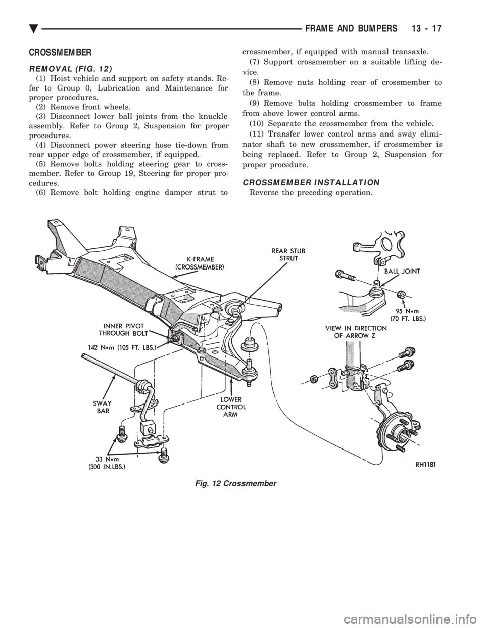
REMOVAL (FIG. 12)
(1) Hoist vehicle and support on safety stands. Re-
fer to Group 0, Lubrication and Maintenance for
proper procedures. (2) Remove front wheels.
(3) Disconnect lower ball joints from the knuckle
assembly. Refer to Group 2, Suspension for proper
procedures. (4) Disconnect power steering hose tie-down from
rear upper edge of crossmember, if equipped. (5) Remove bolts holding steering gear to cross-
member. Refer to Group 19, Steering for proper pro-
cedures. (6) Remove bolt holding engine damper strut to crossmember, if equipped with manual transaxle.
(7) Support crossmember on a suitable lifting de-
vice. (8) Remove nuts holding rear of crossmember to
the frame. (9) Remove bolts holding crossmember to frame
from above lower control arms. (10) Separate the crossmember from the vehicle.
(11) Transfer lower control arms and sway elimi-
nator shaft to new crossmember, if crossmember is
being replaced. Refer to Group 2, Suspension for
proper procedure.
CROSSMEMBER INSTALLATION
Reverse the preceding operation.
Fig. 12 Crossmember
Ä FRAME AND BUMPERS 13 - 17
Page 1745 of 2438
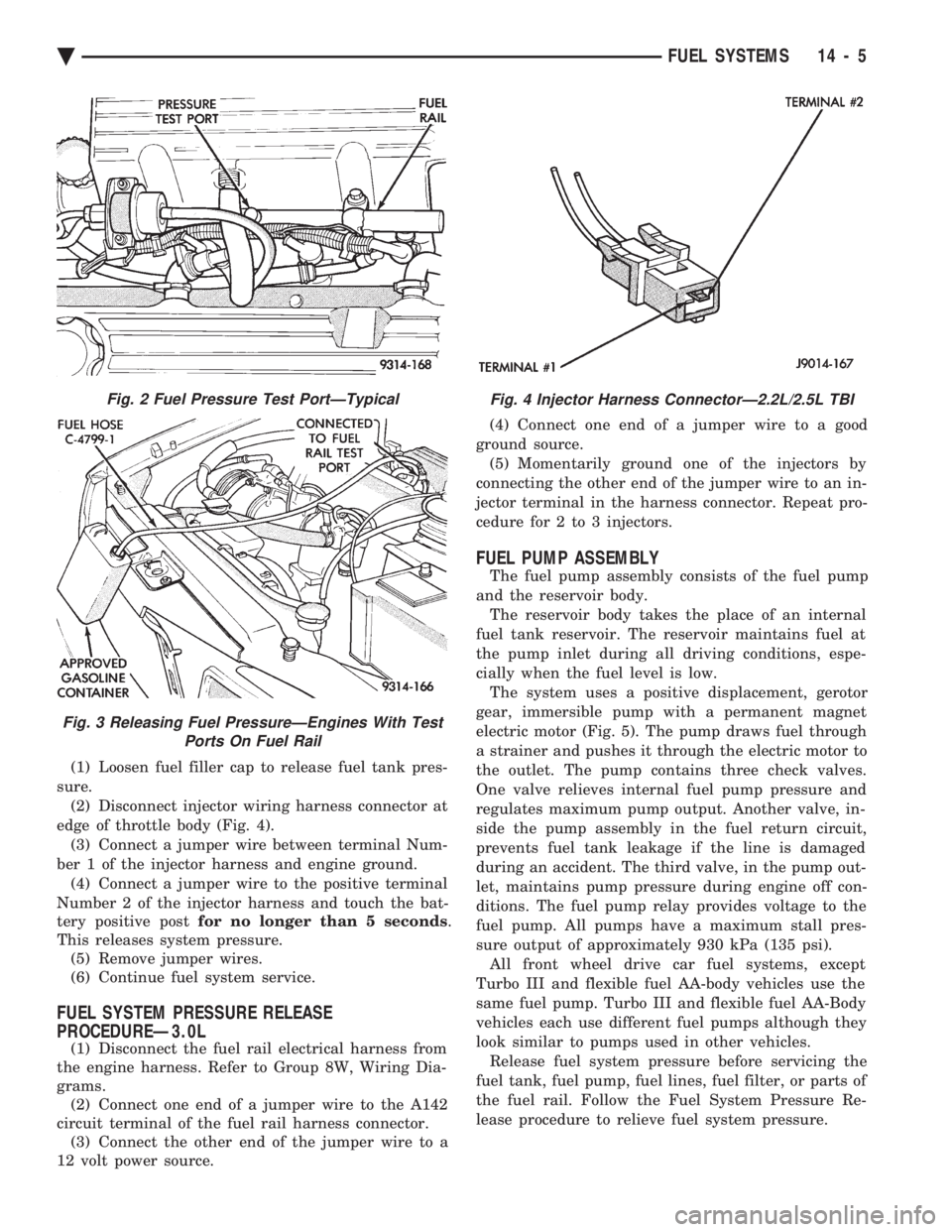
(1) Loosen fuel filler cap to release fuel tank pres-
sure. (2) Disconnect injector wiring harness connector at
edge of throttle body (Fig. 4). (3) Connect a jumper wire between terminal Num-
ber 1 of the injector harness and engine ground. (4) Connect a jumper wire to the positive terminal
Number 2 of the injector harness and touch the bat-
tery positive post for no longer than 5 seconds .
This releases system pressure. (5) Remove jumper wires.
(6) Continue fuel system service.
FUEL SYSTEM PRESSURE RELEASE
PROCEDUREÐ3.0L
(1) Disconnect the fuel rail electrical harness from
the engine harness. Refer to Group 8W, Wiring Dia-
grams. (2) Connect one end of a jumper wire to the A142
circuit terminal of the fuel rail harness connector. (3) Connect the other end of the jumper wire to a
12 volt power source. (4) Connect one end of a jumper wire to a good
ground source. (5) Momentarily ground one of the injectors by
connecting the other end of the jumper wire to an in-
jector terminal in the harness connector. Repeat pro-
cedure for 2 to 3 injectors.
FUEL PUMP ASSEMBLY
The fuel pump assembly consists of the fuel pump
and the reservoir body. The reservoir body takes the place of an internal
fuel tank reservoir. The reservoir maintains fuel at
the pump inlet during all driving conditions, espe-
cially when the fuel level is low. The system uses a positive displacement, gerotor
gear, immersible pump with a permanent magnet
electric motor (Fig. 5). The pump draws fuel through
a strainer and pushes it through the electric motor to
the outlet. The pump contains three check valves.
One valve relieves internal fuel pump pressure and
regulates maximum pump output. Another valve, in-
side the pump assembly in the fuel return circuit,
prevents fuel tank leakage if the line is damaged
during an accident. The third valve, in the pump out-
let, maintains pump pressure during engine off con-
ditions. The fuel pump relay provides voltage to the
fuel pump. All pumps have a maximum stall pres-
sure output of approximately 930 kPa (135 psi). All front wheel drive car fuel systems, except
Turbo III and flexible fuel AA-body vehicles use the
same fuel pump. Turbo III and flexible fuel AA-Body
vehicles each use different fuel pumps although they
look similar to pumps used in other vehicles. Release fuel system pressure before servicing the
fuel tank, fuel pump, fuel lines, fuel filter, or parts of
the fuel rail. Follow the Fuel System Pressure Re-
lease procedure to relieve fuel system pressure.
Fig. 2 Fuel Pressure Test PortÐTypical
Fig. 3 Releasing Fuel PressureÐEngines With Test Ports On Fuel Rail
Fig. 4 Injector Harness ConnectorÐ2.2L/2.5L TBI
Ä FUEL SYSTEMS 14 - 5
Page 1754 of 2438
FUEL TANKS INDEX
page page
Flexible Fuel Vehicles ..................... 14
Fuel Pump Module ....................... 18
Fuel Reservoir ........................... 18
Fuel System Pressure Release ProcedureÐ 2.2L/2.5L TBI .......................... 15
Fuel System Pressure Release ProcedureÐ3.0L . 15
Fuel System Pressure Release ProcedureÐ Except 2.2L/2.5L TBI and 3.0L ............. 15 Fuel Tank
.............................. 16
Fuel Tank Level Sensor ................... 18
Fuel Tank Pressure Relief and Roll-Over Valve . . 20
General Information ....................... 14
Identifying Flexible Fuel Components .......... 14
Methanol Concentration Sensor .............. 18
Pressure Vacuum Fuel Filler Tube Cap ........ 14
Service Precautions for Flexible Fuel Vehicles . . . 14
GENERAL INFORMATION
The fuel tanks of Chrysler Corporation built vehi-
cles are equipped with fuel and vapor controls that
allow the vehicle to pass a full 360É rollover. The fuel delivery system used on front wheel drive
vehicles contains a fuel tank pressure relief/rollover
valve. The valve mounts on the top of the fuel tank.
The valve functions as a pressure relief valve while
the vehicle is upright. The valve also contains a
check valve that prevents fuel from escaping the fuel
tank if the vehicle turns over. The fuel filler cap also acts as a pressure/vacuum
valve. When pressure inside the fuel tank gets too
high or too low, the fuel filler cap opens to relieve
the difference in air pressure. An evaporation control system restricts fuel evapo-
ration into the atmosphere and reduces unburned hy-
drocarbons. Vapors from the fuel tank are collected
in a charcoal filled canister. The vapors are held in
the canister until the engine is operating. When the
engine operates, vapors are drawn through the in-
take manifold into the combustion chambers.
FLEXIBLE FUEL VEHICLES
Beginning this model year, Chrysler began produc-
ing AA-Body vehicles designed to operate on a mix-
ture of gasoline and methanol. These automobiles are
referred to as Flexible Fuel Vehicles. Flexible fuel vehicles can operate on a mixture of
up to 85 percent methanol, 15 percent unleaded gas-
oline. These vehicles also operate on mixtures con-
taining a lower percentage of methanol or just pure
unleaded gasoline. In many cases, the procedures for servicing flexible
fuel components is identical to gasoline only compo-
nents. Refer to the particular Service Procedure in
this section. If the service procedure for flexible fuel
component differs from a gasoline only component,
the title of each service procedure identifies the ap-
plication.
IDENTIFYING FLEXIBLE FUEL COMPONENTS
Flexible Fuel vehicles have unique methanol com-
patible fuel system components. Chrysler identifies
methanol compatible components that could be phys-
ically interchanged with gasoline only parts by color-
ing them green or applying a green label or tag to
them. Even though they may appear physically iden-
tical, components for gasoline only AA-body vehicles
must not be used on flexible fuel vehicles.
SERVICE PRECAUTIONS FOR FLEXIBLE FUEL
VEHICLES
Methanol is more toxic than gasoline. Always re-
lease fuel system pressure before servicing fuel sys-
tem components and wear methanol resistant gloves
and eye protection. Avoid breathing methanol vapors or ingesting
methanol. Headaches, dizziness and even uncon-
sciousness could result from breathing these vapors.
Serious injury, blindness and even death could result
from ingesting methanol. Methanol vapors are extremely flammable and can
travel along the ground. Service vehicles in well ven-
tilated areas and avoid ignition sources. Never
smoke while servicing the vehicle. Do not allow methanol to contact skin. Prolonged
contact with methanol can cause dry skin or an al-
lergic skin reaction. Also, prolonged contact could re-
sult in absorption through the skin.
PRESSURE VACUUM FUEL FILLER TUBE CAP
WARNING: REMOVE FUEL FILLER TUBE CAP TO
RELIEVE TANK PRESSURE BEFORE REMOVING
OR REPAIRING FUEL SYSTEM COMPONENTS.
The loss of any fuel or vapor out of the filler tube
neck is prevented by the use of a safety filler cap.
The cap releases only under significant pressure 10.9
to 13.45 kPa (1.58 to 1.95 psi). The vacuum release
for all gas caps is between .97 and 2.0 kPa (.14 and
.29 psi). The cap must be replaced by a similar unit
in order for the system to remain effective.
14 - 14 FUEL SYSTEMS Ä
Page 1756 of 2438
jector terminal in the harness connector. Repeat pro-
cedure for 2 to 3 injectors.
FUEL TANK
DRAINING FUEL TANK
WARNING: RELEASE FUEL SYSTEM PRESSURE
BEFORE SERVICING FUEL SYSTEM COMPONENTS.
WHEN SERVICING FLEXIBLE FUEL VEHICLES,
WEAR METHANOL RESISTANT GLOVES AND EYE
PROTECTION AND AVOID BREATHING FUMES. DO
NOT ALLOW METHANOL/GASOLINE MIXTURES TO
CONTACT SKIN. SERVICE VEHICLES IN WELL VEN-
TILATED AREAS AND AVOID IGNITION SOURCES.
NEVER SMOKE WHILE SERVICING THE VEHICLE.
(1) Remove fuel filler cap.
(2) Perform the Fuel System Pressure Release pro-
cedure. (3) Remove ground cable from battery.
(4) Raise vehicle on hoist.
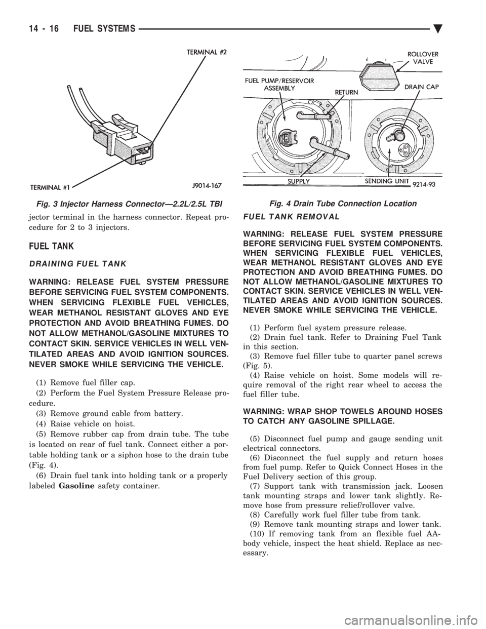
(5) Remove rubber cap from drain tube. The tube
is located on rear of fuel tank. Connect either a por-
table holding tank or a siphon hose to the drain tube
(Fig. 4). (6) Drain fuel tank into holding tank or a properly
labeled Gasoline safety container.
FUEL TANK REMOVAL
WARNING: RELEASE FUEL SYSTEM PRESSURE
BEFORE SERVICING FUEL SYSTEM COMPONENTS.
WHEN SERVICING FLEXIBLE FUEL VEHICLES,
WEAR METHANOL RESISTANT GLOVES AND EYE
PROTECTION AND AVOID BREATHING FUMES. DO
NOT ALLOW METHANOL/GASOLINE MIXTURES TO
CONTACT SKIN. SERVICE VEHICLES IN WELL VEN-
TILATED AREAS AND AVOID IGNITION SOURCES.
NEVER SMOKE WHILE SERVICING THE VEHICLE.
(1) Perform fuel system pressure release.
(2) Drain fuel tank. Refer to Draining Fuel Tank
in this section. (3) Remove fuel filler tube to quarter panel screws
(Fig. 5). (4) Raise vehicle on hoist. Some models will re-
quire removal of the right rear wheel to access the
fuel filler tube.
WARNING: WRAP SHOP TOWELS AROUND HOSES
TO CATCH ANY GASOLINE SPILLAGE.
(5) Disconnect fuel pump and gauge sending unit
electrical connectors. (6) Disconnect the fuel supply and return hoses
from fuel pump. Refer to Quick Connect Hoses in the
Fuel Delivery section of this group. (7) Support tank with transmission jack. Loosen
tank mounting straps and lower tank slightly. Re-
move hose from pressure relief/rollover valve. (8) Carefully work fuel filler tube from tank.
(9) Remove tank mounting straps and lower tank.
(10) If removing tank from an flexible fuel AA-
body vehicle, inspect the heat shield. Replace as nec-
essary.
Fig. 3 Injector Harness ConnectorÐ2.2L/2.5L TBIFig. 4 Drain Tube Connection Location
14 - 16 FUEL SYSTEMS Ä
Page 1785 of 2438
SYSTEMS TEST
WARNING: APPLY PARKING BRAKE AND/OR
BLOCK WHEELS BEFORE PERFORMING A TEST
WITH THE ENGINE OPERATING.
OBTAINING DIAGNOSTIC TROUBLE CODES
(1) Connect DRBII scan tool to the data link con-
nector located in the engine compartment near the
powertrain control module (PCM). (2) Start the engine if possible, cycle the transaxle
selector and the A/Cswitch if applicable. Shut off
the engine. (3) Turn the ignition switch on, access Read Fault
Screen. Record all the fault messages shown on the
DRBII scan tool. Observe the malfunction indicator
lamp (check engine lamp on the instrument panel).
The lamp should light for 3 seconds then go out (bulb
check).
STATE DISPLAY TEST MODE
The switch inputs used by the powertrain control
module (PCM) have only two recognized states,
HIGH and LOW. For this reason, the PCM cannot
recognize the difference between a selected switch po-
sition versus an open circuit, a short circuit, or a de-
fective switch. If the change is displayed, it can be
assumed that the entire switch circuit to the PCM is
functional. From the state display screen access ei-
ther State Display Inputs and Outputs or State Dis-
play Sensors.
STATE DISPLAY INPUTS AND OUTPUTS
Connect the DRBII scan tool to the vehicle and ac-
cess the State Display screen. Then access Inputs and
Outputs. The following is a list of the engine control
system functions accessible through the Inputs and
Outputs screen. Park/Neutral Switch (automatic transaxle only)
Speed Control Resume
Brake Switch
Speed Control On/Off
Speed Control Set
A/C Switch Sense
S/C (Speed Control) Vent Solenoid
S/C (Speed Control) Vacuum Solenoid
Torque Converter Clutch Solenoid (3 speed auto-
matic transaxle)
A/C Clutch Relay
EGR Solenoid
Auto Shutdown Relay
Radiator Fan Relay
Purge Solenoid
Malfunction Indicator (Check Engine) Lamp
STATE DISPLAY SENSORS
Connect the DRBII scan tool to the vehicle and ac-
cess the State Display screen. Then access Sensor
Display. The following is a list of the engine control
system functions accessible through the Sensor Dis-
play screen. Oxygen Sensor Signal
Coolant Temperature
Coolant Temp Sensor
Throttle Position
Minimum Throttle
Battery Voltage
MAP Sensor Reading
Idle Air Control Motor Position
Added Adaptive Fuel
Adaptive Fuel Factor
Barometric Pressure
Min Airflow Idl Spd
Engine Speed
Fault #1 Key-On Info
Module Spark Advance
Speed Control Target
Fault #2 Key-On Info
Fault #3 Key-On Info
Speed Control Status
Charging System Goal
Theft Alarm Status
Speed Control Switch Voltage
Map Sensor Voltage
Vehicle Speed
Oxygen Sensor State
MAP Gauge Reading
Throttle Opening (percentage)
Total Spark Advance
CIRCUIT ACTUATION TEST MODE
The circuit actuation test mode checks for proper
operation of output circuits or devices which the pow-
ertrain control module (PCM) cannot internally rec-
ognize. The PCM can attempt to activate these
outputs and allow an observer to verify proper oper-
ation. Most of the tests provide an audible or visual
indication of device operation (click of relay contacts,
spray fuel, etc.). With the exception of an intermit-
tent condition, if a device functions properly during
its test, it can be assumed that the device, its associ-
ated wiring, and its driver circuit are in working or-
der.
OBTAINING CIRCUIT ACTUATION TEST
Connect the DRBII scan tool to the vehicle and ac-
cess the Actuators screen. The following is a list of
the engine control system functions accessible
through Actuators screens. Stop All Tests
Ignition Coil #1
Fuel Injector #1
Idle Air Control Motor Open/Close
Ä FUEL SYSTEMS 14 - 45