1993 CHEVROLET DYNASTY wheel
[x] Cancel search: wheelPage 2365 of 2438
HEATER-A/C UNIT ASSEMBLYÐREMOVAL AND
INSTALLATION
AP, AC, AY BODY PROCEDURE
WARNING: IF EQUIPPED WITH A/C, THE REFRIG-
ERATION SYSTEM MUST BE COMPLETELY EMPTY
BEFORE PROCEEDING WITH THIS OPERATION.
(1) Disconnect battery NEGATIVE cable.
(2) Drain radiator and disconnect heater hoses at
unit. Tape heater tubes to keep from leaking during
removal. Refer to Group 7, Cooling System. (3) Remove A/C condensate drain and disconnect
vacuum lines. (4) Inside passenger compartment, perform as fol-
lows, according to body designation. (a) AC-body, remove right upper and lower un-
der-panel silencers. (b) AP & AC-bodies, remove steering column
cover. (c) AC-body, remove left under-panel silencer.
(5) Position front seat or right front seat full rear. (a) AP-body, remove right A-pillar trim.
(b) Remove right cowl side trim.
(6) Remove glove box. (a) AC-body, remove right instrument panel re-
inforcement.
(7) AP-body only: (a) Remove right instrument panel lower mount-
ing screw. (b) Remove center bezel.
(c) Remove lower center module cover.
(d) Remove floor console.
(e) Remove instrument panel support brace (from
steering column opening to right cowl side at bot-
tom of instrument panel). (f) Remove instrument panel to support bracket
(below glove box opening). (g) Remove ash receiver.
(h) Remove radio.
(i) Remove panel top cover.
(j) Remove three right side panel to fence (below
windshield) attaching screws.
(8) AC-body, remove ash receiver.
(9) AP body, pull right lower side of instrument
panel rearward. (10) Remove center distribution and defroster
adapter ducts. (11) AP and AC-bodies, disconnect relay module.
(12) AP-body, remove instrument panel to unit
bracket. (13) AP-body, remove lower air distribution duct.
(14) Disconnect blower motor wire connector.
(15) Disconnect demister hoses from top of unit.
(16) For Non-ATC equipped vehicles, disconnect
the temperature control cable flag from the bottom of
the heater-A/C unit. Then un-clip the cable from the
left side of the heat distribution duct. Swing the ca-
ble out of the way to the left. Disconnect the vacuum
lines at the unit. (17) For ATC equipped vehicles, disconnect the in-
strument panel wiring from the rear face of the ATC
control unit. (18) AC body, disconnect right 25-way connector
bracket and fuse block from panel. (19) Fold floor right side carpet back (except AC
body). (20) From engine compartment, remove four unit
attaching nuts. (21) Remove unit hanger strap lower screw, and
rotate strap. (22) Move heater-A/C unit rearward to clear
mounting studs, and lower unit. (23) AP-body, remove demister adapter from top of
unit. (24) While pulling the lower right of instrument
panel rearward: (a) Slide unit upright from under instrument
panel for AP-body. (b) Except for AP-body, rotate unit while pulling
from under instrument panel.
To install, reverse the preceding operation.
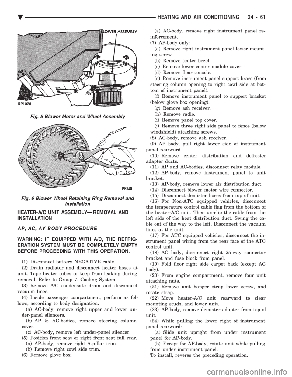
Fig. 5 Blower Motor and Wheel Assembly
Fig. 6 Blower Wheel Retaining Ring Removal and Installation
Ä HEATING AND AIR CONDITIONING 24 - 61
Page 2366 of 2438
AA BODY PROCEDURE
WARNING: IF EQUIPPED WITH A/C, THE REFRIG-
ERATION SYSTEM MUST BE COMPLETELY EMPTY
BEFORE PROCEEDING WITH THIS OPERATION. Refer to Group 8E and Group 23 for component re-
moval and installation when performing this opera-
tion. (1) Perform steps 1 through 7 of Blower Motor re-
moval and installation. (2) Remove relay panel above glove compartment
opening. (3) Disconnect the A/C vacuum line connector and
radio noise capacitor connectors. (4) Remove left windshield pillar trim cover.
(5) Remove left lower side cowl trim cover.
(6) Remove hood release handle mechanism attach-
ing screws. (7) Remove steering column trim covers.
(8) Disconnect parking brake release mechanism
connecting rod. Gain access through fuse panel open-
ing. (9) Remove lower left instrument panel silencer.
(10) Remove lower left instrument panel reinforce-
ment. (11) Remove instrument panel center (radio) bezel.
(12) Remove forward floor console.
(13) Remove the radio.
(14) Remove the heater-A/C control.
(15) Remove cigar lighter.
(16) Remove message center/trip computer, if
equipped. (17) Disconnect side window demister tubes from
top of heat A/C unit. (18) Remove steering column upper attaching bolts
and allow the steering wheel to rest on the driver
seat cushion. (19) Remove upper instrument panel (defroster
outlet) cover. (20) Remove upper instrument panel attaching
screws from below the windshield opening. (21) Loosen (do not remove) the left lower cowl in-
strument panel attaching screw. (22) Remove the right lower cowl instrument panel
attaching screw.
CAUTION: Protect the passenger seat cover from
soiling or damage using a suitable cover.
(23) Carefully pull the right side of the instrument
panel away from the vehicle. Allow the instrument
panel to rest on the passenger seat cushion.
CAUTION: Before proceeding with the next opera-
tion, review the Safety Precautions and Warnings at
the front of this Group. (24) From the engine compartment, drain the cool-
ing system and disconnect the heater hoses from the
heater core nipples. Plug the nipples to avoid spilling
coolant inside the vehicle. (25) Disconnect the refrigerant lines from the ex-
pansion-valve at the dash panel on the right side of
the vehicle. Seal the refrigerant lines to prevent con-
tamination. (26) Remove the expansion valve from the evapo-
rator plate. Seal the valve to avoid contamination. (27) Remove the condensate drain tube.
(28) Remove heater-A/C unit to dash panel attach-
ing nuts. (29) From inside the vehicle, pull rearward on the
heater-A/C unit to clear the dash panel silencer and
remove the unit from the vehicle. To install, reverse the preceding operation. Refill
cooling system and test for leaks. Evacuate and
charge the refrigerant system and test overall perfor-
mance.
AG, AJ BODY PROCEDURE
WARNING: IF EQUIPPED WITH A/C, THE REFRIG-
ERATION SYSTEM MUST BE COMPLETELY EMPTY
BEFORE PROCEEDING WITH THIS OPERATION.
(1) Disconnect the battery negative cable.
(2) Drain the coolant from cooling system. Refer to
Group 7, Cooling System. (3) Remove the air conditioner expansion valve (if
equipped). (4) Disconnect the heater hoses from heater core.
Then plug or cap the tubes on heater core. This will
prevent spilling coolant into the interior of vehicle
during unit removal. (5) Remove the condensate drain tube.
(6) Disconnect the A/C-heater vacuum supply line
from vacuum supply nipple (in the engine compart-
ment). (7) Remove the four A/C-heater assembly-to-dash
panel attaching nuts. (8) Remove the passenger side front seat. Refer to
Group 23, Body. (9) Remove the kick panel/sill cover at right door
opening. (10) Remove the body computer (Fig. 6) located at
the lower right section of the right front door pillar. (11) Remove the glove box assembly. Refer to
Group 8E, Instrument Panel. (12) Remove the carpeted panels from both sides of
the console. (13) Un-clip the radio antenna cable from the
metal support (Fig. 6) located behind and below the
glove box opening. (14) Instrument panel removal is not necessary to
remove the A/C-heater assembly from the vehicle.
24 - 62 HEATING AND AIR CONDITIONING Ä
Page 2377 of 2438
(b) Does the blower motor operate at its highest
speed ? (c) Feel the outlet temperature. Does it get hot
and then cycle cold ? (d) Does the air flow switch from DEFROST out-
lets and then cycle to PANEL outlets?
If you can answer NO to any of these questions,
proceed to step 4, otherwise proceed to step 5. (4) If you answered NO to:
SYMPTOM A
The display symbols and indicators do not illumi-
nate. Diagnostic Trouble Codes are not displayed.
TEST
After self-diagnostic test is complete, select a mode
that will display the malfunction.
ACTION
If the ATC system operates properly, and the dis-
play does not, replace ATC control panel computer.
SYMPTOM B
The blower motor does not operate.
CAUTION: Stay clear of blower motor and power
module (PM) heat sink. Do not run system for more
than 10 minutes with PM removed from A/C unit.
TEST Check all power module and blower motor connec-
tions. Use a voltmeter to test for 12 volts (ignition)
at both ends of the fuse with ignition ON. If fuse is
good, test the green wire at the blower motor connec-
tor for 12 volts (ignition) to body ground. Turn ignition to the ON position.
With the blower motor still connected, check for 12
volts to body ground on the black/tan wire of the
blower motor two way connector. Check for 12 volts at the Power Module pin #4
(BK/TN). Check for continuity from the Power Module pin
#3 (BK) to chassis ground. Replace the Power Module.
ACTION If 12 volts is not detected, repair feed circuit. Refer
to the Front Wheel Drive Car-Wiring Diagrams Ser-
vice Manual. If 12 volts is not detected, repair wires of the
blower motor or replace the blower motor. If 12 volts is not present, repair wire from the
blower motor connector to the Power Module. If circuit is open, repair ground circuit of the Power
Module. Replace the Power Module (power transistor open).
SYMPTOM C
The outlet air temperature does not become hot
and then cycle to cold during self-test operation. Di-
agnostic Trouble Codes are not displayed.
TEST/ACTION
Make sure the blend-air door is properly attached
to the actuator. If cold air is not discharged from the outlets, check
the base A/C refrigerant system. Make sure heating operation works correctly, (wa-
ter level, thermostat, heater hoses, heater core, etc.).
SYMPTOM D
Air does not flow from DEFROST outlets and then
cycle to PANEL outlets during self-test operation.
TEST/ACTION Check linkages from the mode door actuator for
binding. Check for proper door travel in the unit.
(5) The computer will do one of two things:
² Will return to the control settings that were se-
lected before the Diagnostic Test was started. This
means the test is over. If Diagnostic Trouble Codes
did not occur, and answers to questions (a), (b), (c),
and (d) were YES, the entire system is operating cor-
rectly.
² The blower motor will stop and the computer will
flash a Diagnostic Trouble Code number from 01
through 28. Record the number and then depress the
PANEL button to advance to the next test. If the
ATC control flashes one or more codes 23 to 28, the
digits on the display will flash alternating Zeros. If
you do nothing, these codes will remain stored within
the ATC control computer. After all repairs have
been made erase fault codes. Refer to Erasing Diag-
nostic Trouble Codes 23 through 28 from ATC Con-
trol in this section. Repair all Diagnostic Trouble Codes in the order
that they have been indicated, and then retest the
system. If any blend door test fails, all remaining
blend door tests will be skipped. IF any mode door
tests fail, all remaining mode door tests will be
skipped. Diagnostic Test can be stopped at any time by de-
pressing any button other than PANEL.
DIAGNOSTIC TROUBLE CODE DEFINITIONS
Non-computer aided diagnostics should be per-
formed first. Hood of vehicle should be closed during
the diagnostic test to keep engine heat from effecting
the ambient temperature sensor. Also refer to the wiring Pin out charts.
² DIAGNOSTIC TROUBLE CODE 1
Involves the wiring or the ATC control head.
² DIAGNOSTIC TROUBLE CODES 2, 13, 14, 15,
20, and 23
Ä HEATING AND AIR CONDITIONING 24 - 73
Page 2401 of 2438
EVAPORATION CONTROL SYSTEM
The evaporation control system prevents the emis-
sion of fuel tank vapors into the atmosphere. When fuel
evaporates in the fuel tank, the vapors pass through
vent hoses or tubes to a charcoal canister. The canister
temporarily holds the vapors. The powertrain control
module (PCM) allows intake manifold vacuum to draw
vapors into the combustion chambers during certain
operating conditions. The PCM uses the canister purge
solenoid to regulate vapor flow. On 2.2L and 2.5L TBI, 3.3L, and 3.8L engines,
manifold vacuum purges the vapors at idle as well as
off idle. These engines use a bi-level purge system. The
system uses 2 sources of vacuum remove fuel vapors
from the canister. Turbo III engines use a tri-level canister purge sys-
tem. In this system, fuel vapors are drawn into the
engine through the throttle body and air cleaner. Fuel
vapors are drawn in at closed throttle, part throttle,
and wide open throttle (in boost). The 2.5L MPI (flexible fuel AA-Body) and 3.0L have
a duty cycle purge system. The powertrain control
module PCM controls vapor flow by operating the duty
cycle EVAP purge solenoid. Refer to Duty Cycle EVAP
Purge Solenoid in this section. The evaporative system uses specially manu-
factured hoses. If they need replacement, only
use fuel resistant hose.
PRESSURE RELIEF/ROLLOVER VALVE
All vehicles have a combination pressure relief and
rollover valve. The dual function valve relieves fuel
tank pressure. The valve also prevents fuel flow
through the fuel tank vent valve hoses if the vehicle
accidentally rolls over. All vehicles pass a 360É rollover. The pressure relief valve opens at a certain pressure.
When fuel tank pressure increases above the cali-
brated pressure, the valve opens to release fuel tank
vapors pressure. The evaporative (charcoal) canister
stores the vapors. For pressure relief/rollover valve
service, refer to the Fuel Tank section of Group 14.
EVAPORATIVE CANISTER
All vehicles use a sealed, maintenance free, evapora-
tive (charcoal) canister. The canister mounts to the
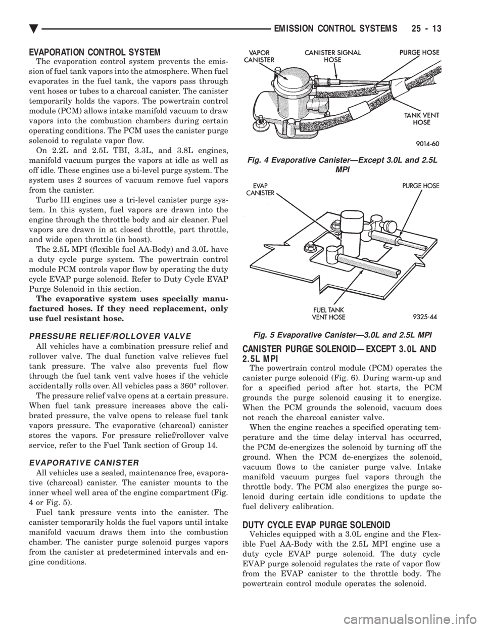
inner wheel well area of the engine compartment (Fig.
4 or Fig. 5). Fuel tank pressure vents into the canister. The
canister temporarily holds the fuel vapors until intake
manifold vacuum draws them into the combustion
chamber. The canister purge solenoid purges vapors
from the canister at predetermined intervals and en-
gine conditions.
CANISTER PURGE SOLENOIDÐEXCEPT 3.0L AND
2.5L MPI
The powertrain control module (PCM) operates the
canister purge solenoid (Fig. 6). During warm-up and
for a specified period after hot starts, the PCM
grounds the purge solenoid causing it to energize.
When the PCM grounds the solenoid, vacuum does
not reach the charcoal canister valve. When the engine reaches a specified operating tem-
perature and the time delay interval has occurred,
the PCM de-energizes the solenoid by turning off the
ground. When the PCM de-energizes the solenoid,
vacuum flows to the canister purge valve. Intake
manifold vacuum purges fuel vapors through the
throttle body. The PCM also energizes the purge so-
lenoid during certain idle conditions to update the
fuel delivery calibration.
DUTY CYCLE EVAP PURGE SOLENOID
Vehicles equipped with a 3.0L engine and the Flex-
ible Fuel AA-Body with the 2.5L MPI engine use a
duty cycle EVAP purge solenoid. The duty cycle
EVAP purge solenoid regulates the rate of vapor flow
from the EVAP canister to the throttle body. The
powertrain control module operates the solenoid.
Fig. 4 Evaporative CanisterÐExcept 3.0L and 2.5L MPI
Fig. 5 Evaporative CanisterÐ3.0L and 2.5L MPI
Ä EMISSION CONTROL SYSTEMS 25 - 13
Page 2403 of 2438
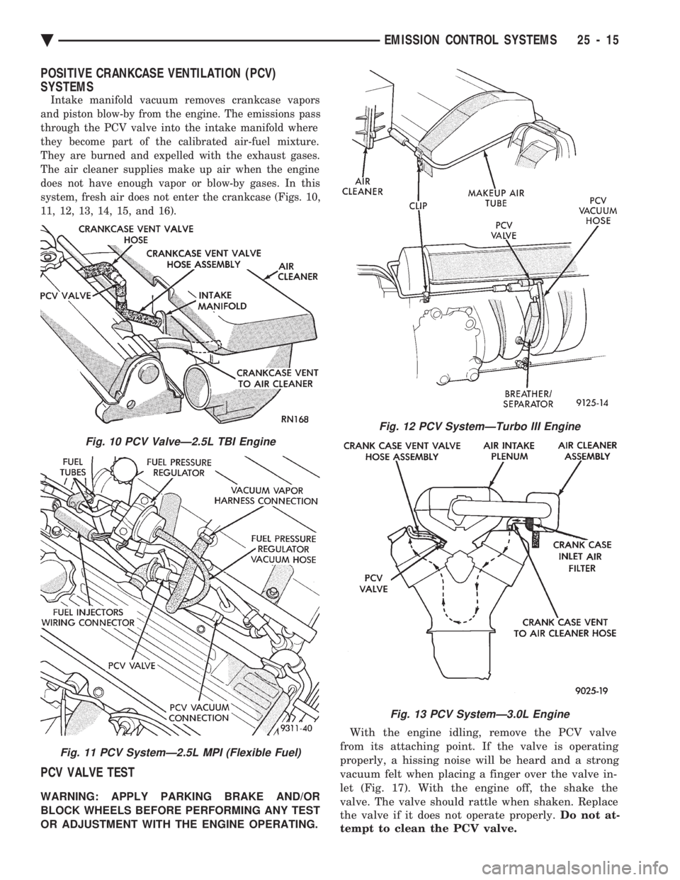
POSITIVE CRANKCASE VENTILATION (PCV)
SYSTEMS
Intake manifold vacuum removes crankcase vapors
and piston blow-by from the engine. The emissions pass
through the PCV valve into the intake manifold where
they become part of the calibrated air-fuel mixture.
They are burned and expelled with the exhaust gases.
The air cleaner supplies make up air when the engine
does not have enough vapor or blow-by gases. In this
system, fresh air does not enter the crankcase (Figs. 10,
11, 12, 13, 14, 15, and 16).
PCV VALVE TEST
WARNING: APPLY PARKING BRAKE AND/OR
BLOCK WHEELS BEFORE PERFORMING ANY TEST
OR ADJUSTMENT WITH THE ENGINE OPERATING. With the engine idling, remove the PCV valve
from its attaching point. If the valve is operating
properly, a hissing noise will be heard and a strong
vacuum felt when placing a finger over the valve in-
let (Fig. 17). With the engine off, the shake the
valve. The valve should rattle when shaken. Replace
the valve if it does not operate properly. Do not at-
tempt to clean the PCV valve.
Fig. 10 PCV ValveÐ2.5L TBI Engine
Fig. 11 PCV SystemÐ2.5L MPI (Flexible Fuel)
Fig. 12 PCV SystemÐTurbo III Engine
Fig. 13 PCV SystemÐ3.0L Engine
Ä EMISSION CONTROL SYSTEMS 25 - 15
Page 2409 of 2438
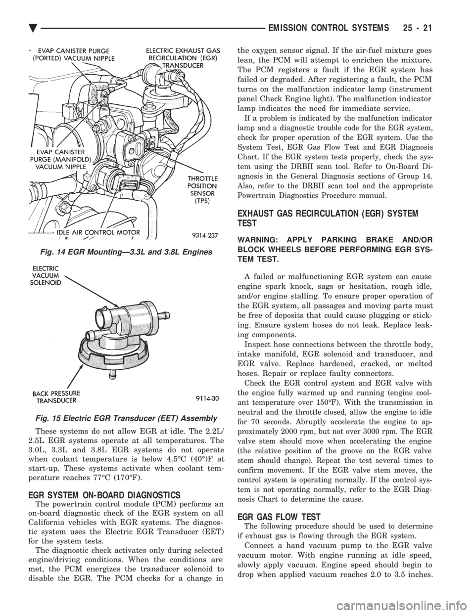
These systems do not allow EGR at idle. The 2.2L/
2.5L EGR systems operate at all temperatures. The
3.0L, 3.3L and 3.8L EGR systems do not operate
when coolant temperature is below 4.5ÉC (40É)F at
start-up. These systems activate when coolant tem-
perature reaches 77ÉC (170ÉF).
EGR SYSTEM ON-BOARD DIAGNOSTICS
The powertrain control module (PCM) performs an
on-board diagnostic check of the EGR system on all
California vehicles with EGR systems. The diagnos-
tic system uses the Electric EGR Transducer (EET)
for the system tests. The diagnostic check activates only during selected
engine/driving conditions. When the conditions are
met, the PCM energizes the transducer solenoid to
disable the EGR. The PCM checks for a change in the oxygen sensor signal. If the air-fuel mixture goes
lean, the PCM will attempt to enrichen the mixture.
The PCM registers a fault if the EGR system has
failed or degraded. After registering a fault, the PCM
turns on the malfunction indicator lamp (instrument
panel Check Engine light). The malfunction indicator
lamp indicates the need for immediate service.
If a problem is indicated by the malfunction indicator
lamp and a diagnostic trouble code for the EGR system,
check for proper operation of the EGR system. Use the
System Test, EGR Gas Flow Test and EGR Diagnosis
Chart. If the EGR system tests properly, check the sys-
tem using the DRBII scan tool. Refer to On-Board Di-
agnosis in the General Diagnosis sections of Group 14.
Also, refer to the DRBII scan tool and the appropriate
Powertrain Diagnostics Procedure manual.
EXHAUST GAS RECIRCULATION (EGR) SYSTEM
TEST
WARNING: APPLY PARKING BRAKE AND/OR
BLOCK WHEELS BEFORE PERFORMING EGR SYS-
TEM TEST.
A failed or malfunctioning EGR system can cause
engine spark knock, sags or hesitation, rough idle,
and/or engine stalling. To ensure proper operation of
the EGR system, all passages and moving parts must
be free of deposits that could cause plugging or stick-
ing. Ensure system hoses do not leak. Replace leak-
ing components. Inspect hose connections between the throttle body,
intake manifold, EGR solenoid and transducer, and
EGR valve. Replace hardened, cracked, or melted
hoses. Repair or replace faulty connectors.
Check the EGR control system and EGR valve with
the engine fully warmed up and running (engine cool-
ant temperature over 150ÉF). With the transmission in
neutral and the throttle closed, allow the engine to idle
for 70 seconds. Abruptly accelerate the engine to ap-
proximately 2000 rpm, but not over 3000 rpm. The EGR
valve stem should move when accelerating the engine
(the relative position of the groove on the EGR valve
stem should change). Repeat the test several times to
confirm movement. If the EGR valve stem moves, the
control system is operating normally. If the control sys-
tem is not operating normally, refer to the EGR Diag-
nosis Chart to determine the cause.
EGR GAS FLOW TEST
The following procedure should be used to determine
if exhaust gas is flowing through the EGR system.
Connect a hand vacuum pump to the EGR valve
vacuum motor. With engine running at idle speed,
slowly apply vacuum. Engine speed should begin to
drop when applied vacuum reaches 2.0 to 3.5 inches.
Fig. 14 EGR MountingÐ3.3L and 3.8L Engines
Fig. 15 Electric EGR Transducer (EET) Assembly
Ä EMISSION CONTROL SYSTEMS 25 - 21
Page 2413 of 2438
CHRYSLER
CORPORATION
SERVICE MANUAL and SUPPLEMENTS
1993 FRONT WHEEL DRIVE PASSENGER VEHICLES
To order the special service tools used and
illustrated, please refer to the instructions on
inside back cover.
NO PART OF THIS PUBLICATION MAY BE
REPRODUCED, STORED IN A RETRIEVAL
SYSTEM, OR TRANSMITTED, IN ANY FORM
OR BY ANY MEANS, ELECTRONIC, ME-
CHANICAL, PHOTOCOPYING, RECORDING,
OR OTHERWISE, WITHOUT THE PRIOR
WRITTEN PERMISSION OF CHRYSLER
CORPORATION.
Chrysler Corporation reserves the right to make changes in design or to make
additions to or improvements in its products without imposing any obligations
upon itself to install them on its products previously manufactured.
Litho in U.S.A. Copyright 1992 Chrysler Corporation 30M0792
NEXT PAGE ©