1993 CHEVROLET DYNASTY wheel
[x] Cancel search: wheelPage 2300 of 2438
(6) Pull trim panel forward and separate from ve-
hicle. (7) Remove bolt holding lap belt anchor to floor
and push end of belt through access hole in trim
panel.
INSTALLATION
Reverse the preceding operation.
REAR SHELF TRIM PANEL
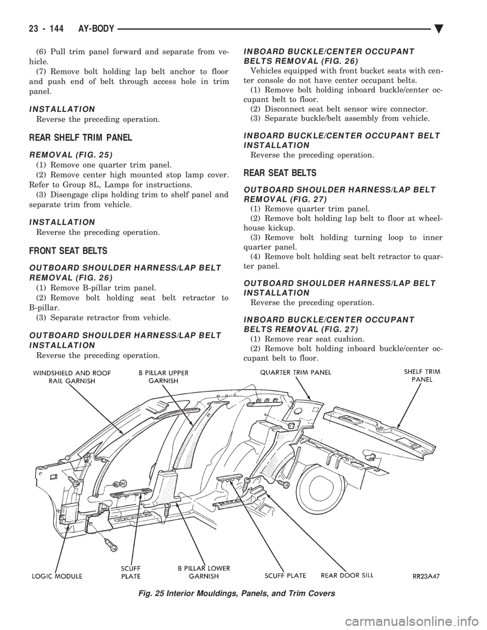
REMOVAL (FIG. 25)
(1) Remove one quarter trim panel.
(2) Remove center high mounted stop lamp cover.
Refer to Group 8L, Lamps for instructions. (3) Disengage clips holding trim to shelf panel and
separate trim from vehicle.
INSTALLATION
Reverse the preceding operation.
FRONT SEAT BELTS
OUTBOARD SHOULDER HARNESS/LAP BELT REMOVAL (FIG. 26)
(1) Remove B-pillar trim panel.
(2) Remove bolt holding seat belt retractor to
B-pillar. (3) Separate retractor from vehicle.
OUTBOARD SHOULDER HARNESS/LAP BELTINSTALLATION
Reverse the preceding operation.
INBOARD BUCKLE/CENTER OCCUPANT BELTS REMOVAL (FIG. 26)
Vehicles equipped with front bucket seats with cen-
ter console do not have center occupant belts. (1) Remove bolt holding inboard buckle/center oc-
cupant belt to floor. (2) Disconnect seat belt sensor wire connector.
(3) Separate buckle/belt assembly from vehicle.
INBOARD BUCKLE/CENTER OCCUPANT BELT INSTALLATION
Reverse the preceding operation.
REAR SEAT BELTS
OUTBOARD SHOULDER HARNESS/LAP BELTREMOVAL (FIG. 27)
(1) Remove quarter trim panel.
(2) Remove bolt holding lap belt to floor at wheel-
house kickup. (3) Remove bolt holding turning loop to inner
quarter panel. (4) Remove bolt holding seat belt retractor to quar-
ter panel.
OUTBOARD SHOULDER HARNESS/LAP BELT INSTALLATION
Reverse the preceding operation.
INBOARD BUCKLE/CENTER OCCUPANTBELTS REMOVAL (FIG. 27)
(1) Remove rear seat cushion.
(2) Remove bolt holding inboard buckle/center oc-
cupant belt to floor.
Fig. 25 Interior Mouldings, Panels, and Trim Covers
23 - 144 AY-BODY Ä
Page 2302 of 2438
(3) Remove cushion from vehicle.
REAR SEAT CUSHION INSTALLATION
Reverse the preceding operation.
REAR SEAT BACK REMOVAL
(1) Remove rear seat cushion assembly.
(2) Remove bolts holding seat back to rear floor
kick-up. (3) Lift seat back upward to disengage upper hooks
from shelf support panel. (4) Separate seat back from vehicle.
REAR SEAT BACK INSTALLATION
Reverse the preceding operation.
BODY MOULDINGS
STICK-ON BODY SIDE MOULDING REMOVALAND INSTALLATION
(1) Warm the effected stick-on moulding and body
metal to approximately 38ÉC (100ÉF) using a suitable
heat lamp or heat gun. (2) Pull stick-on moulding from painted surface.
(3) Remove adhesive tape residue from painted
surface of vehicle. (4) If moulding is to be reused, Remove tape resi-
due from moulding. Clean back of moulding with Mo-
par, Super Kleen solvent or equivalent. Wipe
moulding dry with lint free cloth. Apply new body
side moulding (two sided adhesive) tape to back of
moulding. (5) Clean body surface with Mopar, Super Kleen
solvent or equivalent. Wipe surface dry with lint free
cloth. (6) Apply a length of masking tape on the body,
parallel to the top edge of the moulding to use as a
guide, if necessary. (7) Remove protective cover from tape on back of
moulding. Apply moulding to body below the mask-
ing tape guide. (8) Remove masking tape guide and heat body and
moulding, see step one. Firmly press moulding to
body surface to assure adhesion.
FRONT WHEEL OPENING MOULDING REMOVAL
(1) Remove screws holding wheel opening mould-
ing to front fender. (2) Separate moulding from fender.
FRONT WHEEL OPENING MOULDINGINSTALLATION
(1) Position moulding in wheel opening and start
top center screw of wheel opening moulding. (2) Install screws around wheel opening.
REAR WHEEL OPENING MOULDING REMOVAL
(1) Remove screws holding wheel opening mould-
ing to quarter panel. (2) Separate wheel opening moulding from quarter
panel.
REAR WHEEL OPENING MOULDING INSTALLATION
(1) Position moulding in wheel opening and start
top center screw of wheel opening moulding. (2) Install screws around wheel opening.
VINYL ROOF BONNET
REMOVAL (FIG. 30)
(1) Remove quarter panel trim covers.
(2) Remove head lining.
(3) Remove nuts holding transverse roof moulding
to roof panel and separate moulding from vehicle. (4) Remove nuts holding vinyl top bonnet to roof.
(5) Remove rear deck filler panel.
(6) Remove screws holding rear window opening
lower valance to body. (7) Disengage clips holding vinyl top bonnet to
quarter panel. (8) Pull vinyl top bonnet away from top panel to
separate bonnet from anti-flutter sealer holding bon-
net to roof.
INSTALLATION
(1) Clean anti-flutter sealer from roof surface and
inside of vinyl roof bonnet. (2) Apply a 20 mm (0.75 in.) bead of anti-flutter
sealer across the roof panel at the mid point between
the front of the bonnet and rear of roof. (3) Apply a 20 mm (0.75 in.) by 150 mm (6 in.)
bead of anti-flutter sealer down each roof side panel
at mid point between the door opening and rear of
roof. (4) Place the bonnet into position on the roof panel
and align to proper fit. (5) Reverse the removal operation.
REAR DECK FILLER PANEL
REMOVAL (FIG. 31)
(1) Raise truck lid to full up position.
(2) Remove screws holding rear deck filler panel to
body in the front trunk opening gutter. (3) Close trunk lid, do not latch.
(4) Lift filler panel upward and separate from ve-
hicle.
INSTALLATION
Reverse the preceding operation.
23 - 146 AY-BODY Ä
Page 2312 of 2438
REFRIGERANT SERVICE PROCEDURES INDEX
page page
Adding Partial Refrigerant Charge ............ 10
Charging Refrigerant SystemÐEmpty System . . . 11
Discharging Refrigerant System .............. 11
Evacuating Refrigerant System .............. 11
Manifold Gauge Set Connections ............. 9 Oil Level
............................... 12
R-12 Refrigerant Equipment ................. 8
Refrigerant Recycling ...................... 9
Sight Glass Refrigerant Level Inspection ........ 8
Testing for Refrigerant Leaks ............... 10
SIGHT GLASS REFRIGERANT LEVEL INSPECTION
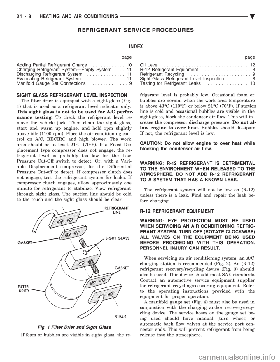
The filter-drier is equipped with a sight glass (Fig.
1) that is used as a refrigerant level indicator only.
This sight glass is not to be used for A/C perfor-
mance testing. To check the refrigerant level re-
move the vehicle jack. Then clean the sight glass,
start and warm up engine, and hold rpm slightly
above idle (1100 rpm). Place the air conditioning con-
trol on A/C, RECIRC and high blower. The work
area should be at least 21ÉC (70ÉF). If a Fixed Dis-
placement type compressor does not engage, the re-
frigerant level is probably too low for the Low
Pressure Cut-Off switch to detect. Or, with a Vari-
able Displacement compressor, for the Differential
Pressure Cut-off to detect. If compressor clutch does
not engage, test the refrigerant system for leaks. If
compressor clutch engages, allow approximately one
minute for refrigerant to stabilize. View refrigerant
through sight glass. The suction line should be cold
to the touch and the sight glass should be clear.
If foam or bubbles are visible in sight glass, the re- frigerant level is probably low. Occasional foam or
bubbles are normal when the work area temperature
is above 43ÉC (110ÉF) or below 21ÉC (70ÉF). If suction
line is cold and occasional bubbles are visible in the
sight glass, block the condenser air flow. This will in-
crease the compressor discharge pressure. Do not al-
low engine to over heat. Bubbles should dissipate.
If not, the refrigerant level is low.
CAUTION: Do not allow engine to over heat while
blocking the condenser air flow.
WARNING: R-12 REFRIGERANT IS DETRIMENTAL
TO THE ENVIRONMENT WHEN RELEASED TO THE
ATMOSPHERE. DO NOT ADD R-12 REFRIGERANT
TO A SYSTEM THAT HAS A KNOWN LEAK.
The refrigerant system will not be low on (R-12)
unless there is a leak. Find and repair the leak be-
fore charging.
R-12 REFRIGERANT EQUIPMENT
WARNING: EYE PROTECTION MUST BE USED
WHEN SERVICING AN AIR CONDITIONING REFRIG-
ERANT SYSTEM. TURN OFF (ROTATE CLOCKWISE)
ALL VALVES ON THE EQUIPMENT BEING USED
BEFORE PROCEEDING WITH THIS OPERATION.
PERSONNEL INJURY CAN RESULT.
When servicing an air conditioning system, an A/C
charging station is recommended (Fig. 2). An (R-12)
refrigerant recovery/recycling device (Fig. 3) should
also be used. This device should meet SAE standards.
Contact an automotive service equipment supplier
for refrigerant recycling/recovering equipment. Refer
to the operating instructions provided with the
equipment for proper operation. A manifold gauge set (Fig. 4) must also be used in
conjunction with the charging and/or recovery/recy-
cling device. The service hoses on the gauge set be-
ing used should have manual (turn wheel) or
automatic back flow valves at the service port con-
nector ends. This will prevent refrigerant from being
release into the atmosphere.
Fig. 1 Filter Drier and Sight Glass
24 - 8 HEATING AND AIR CONDITIONING Ä
Page 2342 of 2438
FIXED DISPLACEMENT COMPRESSORÐMODEL SD709P INDEX
page page
Compressor ............................. 38
Compressor Clutch/Coil Assembly ............ 38
Compressor Shaft Seal .................... 41 Cylinder Head/Valve Plate
.................. 44
Description ............................. 38
Refrigerant System Diagnosis ............... 45
DESCRIPTION
The Sanden compressor is a 7 piston design. Sys-
tem lubrication is provided by 135 ml 615 ml (4.6 oz.
6 0.5 oz.) of 500 viscosity refrigerant oil.
The clutch used on the compressor consists of 3 ba-
sic components:
² The pulley
² Front plate
² Field coil
The pulley and field coil are attached to the front
head of the compressor with tapered snap rings. The
hub is keyed to the compressor shaft and is retained
on the shaft with a self-locking nut. Special service
tools are required to remove and install the clutch
plate on the compressor shaft.
COMPRESSOR
The A/C compressor may be removed and posi-
tioned without discharging the refrigerant system.
Discharging is not necessary if removing the A/C
compressor clutch/coil assembly, engine, cylinder
head, or generator.
WARNING: REFRIGERANT PRESSURES REMAIN
HIGH EVEN THOUGH THE ENGINE MAY BE
TURNED OFF. BEFORE REMOVING A FULLY
CHARGED COMPRESSOR, REVIEW THE SAFETY
PRECAUTIONS AND WARNINGS SECTION IN THIS
GROUP. DO NOT TWIST OR KINK THE REFRIGER-
ANT LINES WHEN REMOVING A FULLY CHARGED
COMPRESSOR. SAFETY GLASSES MUST BE
WORN.
REMOVAL
(1) Disconnect negative cable from battery.
(2) Loosen and remove drive belts (refer to group
7, Cooling System) and disconnect compressor clutch
wire lead. (3) Remove refrigerant lines from compressor (if
necessary). (4) Remove compressor attaching nuts and bolts.
(5) Remove compressor. If refrigerant lines were
not removed, lift compressor/clutch assembly and tie
it to a suitable component. To install, reverse the removal procedure.
COMPRESSOR CLUTCH/COIL ASSEMBLY
The magnetic clutch consists of a stationary elec-
tro-magnetic coil and a rotating pulley and plate as-
sembly. The electromagnetic coil is retained on the com-
pressor with a snap ring and is dimpled to maintain
its position. The pulley and plate assembly are mounted on the
compressor shaft. When the compressor is not in operation, the pul-
ley free wheels on the clutch hub bearing. When the
coil is energized the plate is magnetically engaged
with the pulley and turns the compressor shaft.
REMOVAL
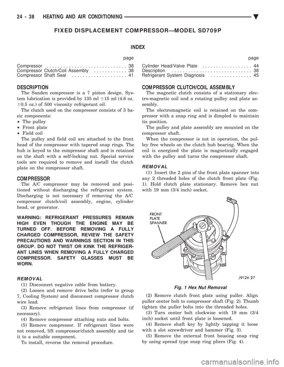
(1) Insert the 2 pins of the front plate spanner into
any 2 threaded holes of the clutch front plate (Fig.
1). Hold clutch plate stationary. Remove hex nut
with 19 mm (3/4 inch) socket.
(2) Remove clutch front plate using puller. Align
puller center bolt to compressor shaft (Fig. 2). Thumb
tighten the puller bolts into the threaded holes. (3) Turn center bolt clockwise with 19 mm (3/4
inch) socket until front plate is loosened. (4) Remove shaft key by lightly tapping it loose
with a slot screwdriver and hammer (Fig. 3). (5) Remove the external front housing snap ring
by using spread type snap ring pliers (Fig. 4).
Fig. 1 Hex Nut Removal
24 - 38 HEATING AND AIR CONDITIONING Ä
Page 2351 of 2438
COMPONENT SERVICE PROCEDURES INDEX
page page
Air Distribution Duct ...................... 50
Air Distribution Duct ...................... 52
Ambient Switch .......................... 47
Blend-Air Door .......................... 64
Blower Motor ............................ 58
Blower Motor Wheel Assembly .............. 58
Blower Resistor Block ..................... 49
Condensate Drain Tube ................... 64
Condenser Assembly ...................... 57
Condenser Fan Control Switch .............. 47
Defroster Duct ........................... 51
Defroster Duct Adapter .................... 51
Defroster Ducts/Demister Ducts and Hoses ..... 52
Differential Pressure Cut-Out Switch Diagnosis . . 48
Evaporator Coil .......................... 64 Expansion Valve
......................... 55
Filter-Drier Assembly ...................... 57
Fin-Sensing Cycling Clutch Switch ............ 53
Heater Core ............................ 64
Heater Hoses ........................... 51
Heater-A/C Unit AssemblyÐRemoval and Installation ............................ 61
Heater-A/C Unit Recondition ................ 63
Low or Differential Pressure Cut-Off Switch ..... 54
Temperature Control CableÐAA,AP,AG and AJ Models ............................ 49
Temperature Control CableÐAC/AY Models .... 48
Vacuum ActuatorÐFresh/Recirc Door ......... 50
Vacuum ActuatorsÐMode Doors ............. 52
AMBIENT SWITCH
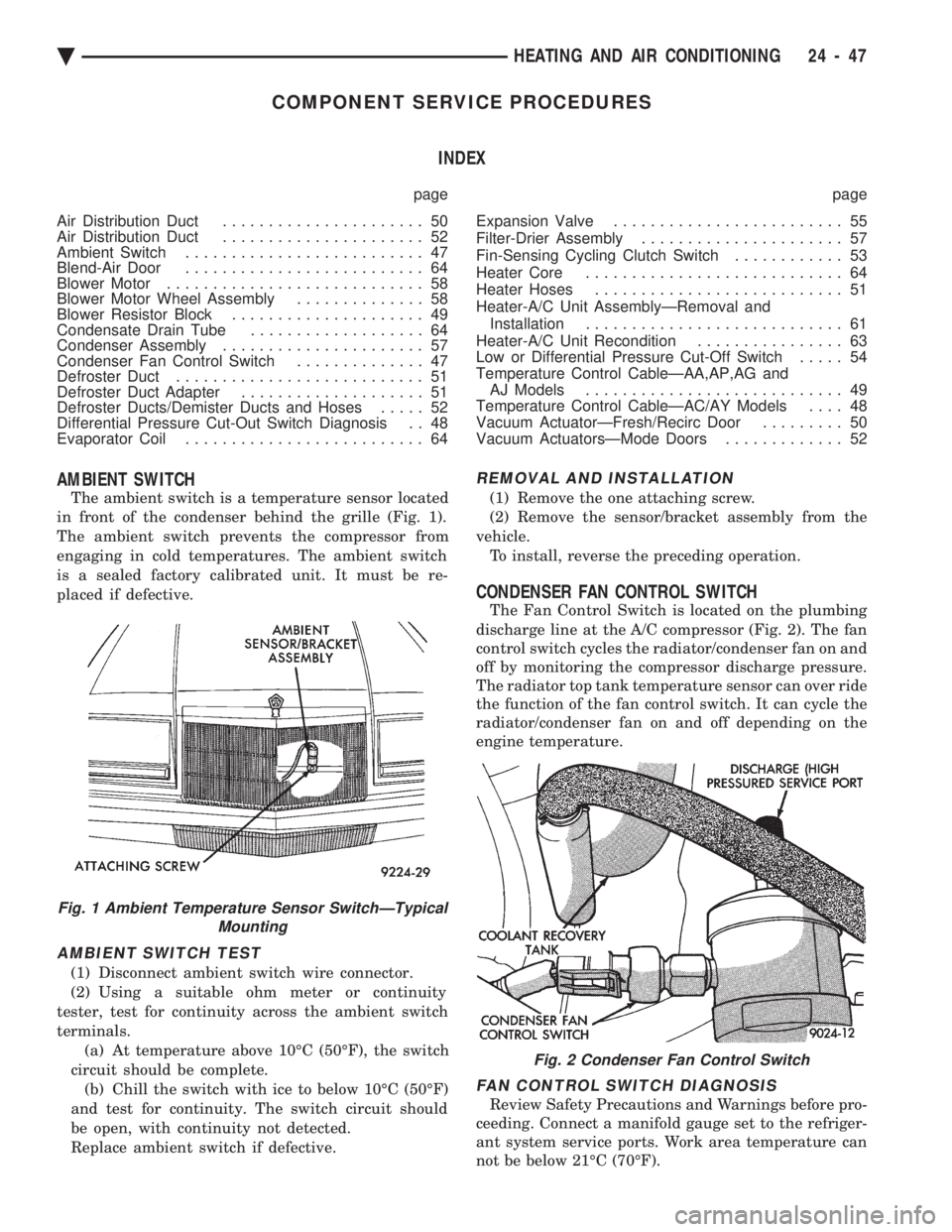
The ambient switch is a temperature sensor located
in front of the condenser behind the grille (Fig. 1).
The ambient switch prevents the compressor from
engaging in cold temperatures. The ambient switch
is a sealed factory calibrated unit. It must be re-
placed if defective.
AMBIENT SWITCH TEST
(1) Disconnect ambient switch wire connector.
(2) Using a suitable ohm meter or continuity
tester, test for continuity across the ambient switch
terminals. (a) At temperature above 10ÉC (50ÉF), the switch
circuit should be complete. (b) Chill the switch with ice to below 10ÉC (50ÉF)
and test for continuity. The switch circuit should
be open, with continuity not detected.
Replace ambient switch if defective.
REMOVAL AND INSTALLATION
(1) Remove the one attaching screw.
(2) Remove the sensor/bracket assembly from the
vehicle. To install, reverse the preceding operation.
CONDENSER FAN CONTROL SWITCH
The Fan Control Switch is located on the plumbing
discharge line at the A/C compressor (Fig. 2). The fan
control switch cycles the radiator/condenser fan on and
off by monitoring the compressor discharge pressure.
The radiator top tank temperature sensor can over ride
the function of the fan control switch. It can cycle the
radiator/condenser fan on and off depending on the
engine temperature.
FAN CONTROL SWITCH DIAGNOSIS
Review Safety Precautions and Warnings before pro-
ceeding. Connect a manifold gauge set to the refriger-
ant system service ports. Work area temperature can
not be below 21ÉC (70ÉF).
Fig. 1 Ambient Temperature Sensor SwitchÐTypical Mounting
Fig. 2 Condenser Fan Control Switch
Ä HEATING AND AIR CONDITIONING 24 - 47
Page 2357 of 2438
FIN-SENSING CYCLING CLUTCH SWITCH
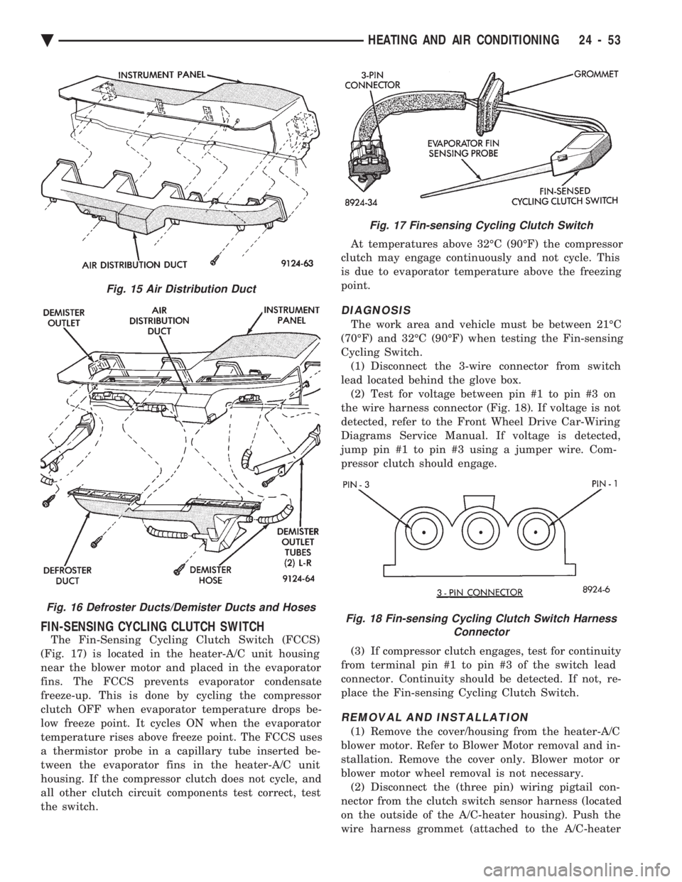
The Fin-Sensing Cycling Clutch Switch (FCCS)
(Fig. 17) is located in the heater-A/C unit housing
near the blower motor and placed in the evaporator
fins. The FCCS prevents evaporator condensate
freeze-up. This is done by cycling the compressor
clutch OFF when evaporator temperature drops be-
low freeze point. It cycles ON when the evaporator
temperature rises above freeze point. The FCCS uses
a thermistor probe in a capillary tube inserted be-
tween the evaporator fins in the heater-A/C unit
housing. If the compressor clutch does not cycle, and
all other clutch circuit components test correct, test
the switch. At temperatures above 32ÉC (90ÉF) the compressor
clutch may engage continuously and not cycle. This
is due to evaporator temperature above the freezing
point.
DIAGNOSIS
The work area and vehicle must be between 21ÉC
(70ÉF) and 32ÉC (90ÉF) when testing the Fin-sensing
Cycling Switch. (1) Disconnect the 3-wire connector from switch
lead located behind the glove box. (2) Test for voltage between pin #1 to pin #3 on
the wire harness connector (Fig. 18). If voltage is not
detected, refer to the Front Wheel Drive Car-Wiring
Diagrams Service Manual. If voltage is detected,
jump pin #1 to pin #3 using a jumper wire. Com-
pressor clutch should engage.
(3) If compressor clutch engages, test for continuity
from terminal pin #1 to pin #3 of the switch lead
connector. Continuity should be detected. If not, re-
place the Fin-sensing Cycling Clutch Switch.
REMOVAL AND INSTALLATION
(1) Remove the cover/housing from the heater-A/C
blower motor. Refer to Blower Motor removal and in-
stallation. Remove the cover only. Blower motor or
blower motor wheel removal is not necessary. (2) Disconnect the (three pin) wiring pigtail con-
nector from the clutch switch sensor harness (located
on the outside of the A/C-heater housing). Push the
wire harness grommet (attached to the A/C-heater
Fig. 15 Air Distribution Duct
Fig. 16 Defroster Ducts/Demister Ducts and Hoses
Fig. 17 Fin-sensing Cycling Clutch Switch
Fig. 18 Fin-sensing Cycling Clutch Switch Harness Connector
Ä HEATING AND AIR CONDITIONING 24 - 53
Page 2358 of 2438
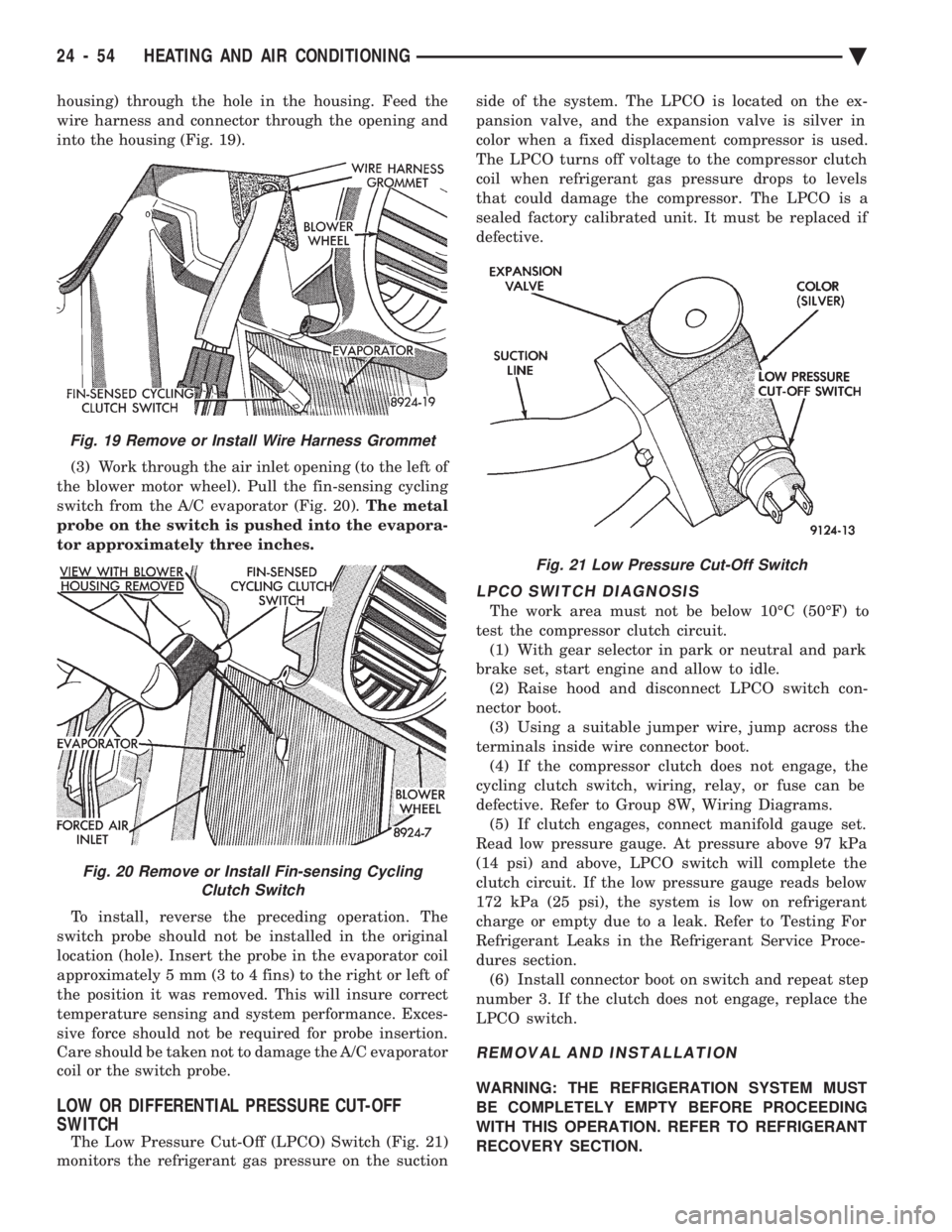
housing) through the hole in the housing. Feed the
wire harness and connector through the opening and
into the housing (Fig. 19). (3) Work through the air inlet opening (to the left of
the blower motor wheel). Pull the fin-sensing cycling
switch from the A/C evaporator (Fig. 20). The metal
probe on the switch is pushed into the evapora-
tor approximately three inches.
To install, reverse the preceding operation. The
switch probe should not be installed in the original
location (hole). Insert the probe in the evaporator coil
approximately 5 mm (3 to 4 fins) to the right or left of
the position it was removed. This will insure correct
temperature sensing and system performance. Exces-
sive force should not be required for probe insertion.
Care should be taken not to damage the A/C evaporator
coil or the switch probe.
LOW OR DIFFERENTIAL PRESSURE CUT-OFF
SWITCH
The Low Pressure Cut-Off (LPCO) Switch (Fig. 21)
monitors the refrigerant gas pressure on the suction side of the system. The LPCO is located on the ex-
pansion valve, and the expansion valve is silver in
color when a fixed displacement compressor is used.
The LPCO turns off voltage to the compressor clutch
coil when refrigerant gas pressure drops to levels
that could damage the compressor. The LPCO is a
sealed factory calibrated unit. It must be replaced if
defective.
LPCO SWITCH DIAGNOSIS
The work area must not be below 10ÉC (50ÉF) to
test the compressor clutch circuit. (1) With gear selector in park or neutral and park
brake set, start engine and allow to idle. (2) Raise hood and disconnect LPCO switch con-
nector boot. (3) Using a suitable jumper wire, jump across the
terminals inside wire connector boot. (4) If the compressor clutch does not engage, the
cycling clutch switch, wiring, relay, or fuse can be
defective. Refer to Group 8W, Wiring Diagrams. (5) If clutch engages, connect manifold gauge set.
Read low pressure gauge. At pressure above 97 kPa
(14 psi) and above, LPCO switch will complete the
clutch circuit. If the low pressure gauge reads below
172 kPa (25 psi), the system is low on refrigerant
charge or empty due to a leak. Refer to Testing For
Refrigerant Leaks in the Refrigerant Service Proce-
dures section. (6) Install connector boot on switch and repeat step
number 3. If the clutch does not engage, replace the
LPCO switch.
REMOVAL AND INSTALLATION
WARNING: THE REFRIGERATION SYSTEM MUST
BE COMPLETELY EMPTY BEFORE PROCEEDING
WITH THIS OPERATION. REFER TO REFRIGERANT
RECOVERY SECTION.
Fig. 21 Low Pressure Cut-Off Switch
Fig. 19 Remove or Install Wire Harness Grommet
Fig. 20 Remove or Install Fin-sensing Cycling Clutch Switch
24 - 54 HEATING AND AIR CONDITIONING Ä
Page 2362 of 2438
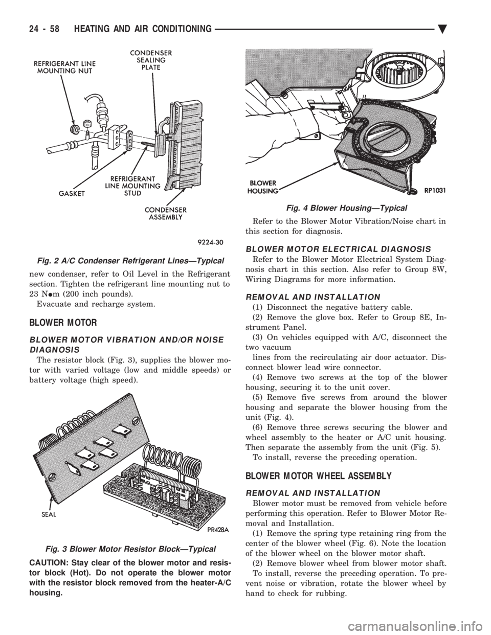
new condenser, refer to Oil Level in the Refrigerant
section. Tighten the refrigerant line mounting nut to
23 N Im (200 inch pounds).
Evacuate and recharge system.
BLOWER MOTOR
BLOWER MOTOR VIBRATION AND/OR NOISE DIAGNOSIS
The resistor block (Fig. 3), supplies the blower mo-
tor with varied voltage (low and middle speeds) or
battery voltage (high speed).
CAUTION: Stay clear of the blower motor and resis-
tor block (Hot). Do not operate the blower motor
with the resistor block removed from the heater-A/C
housing. Refer to the Blower Motor Vibration/Noise chart in
this section for diagnosis.
BLOWER MOTOR ELECTRICAL DIAGNOSIS
Refer to the Blower Motor Electrical System Diag-
nosis chart in this section. Also refer to Group 8W,
Wiring Diagrams for more information.
REMOVAL AND INSTALLATION
(1) Disconnect the negative battery cable.
(2) Remove the glove box. Refer to Group 8E, In-
strument Panel. (3) On vehicles equipped with A/C, disconnect the
two vacuum lines from the recirculating air door actuator. Dis-
connect blower lead wire connector. (4) Remove two screws at the top of the blower
housing, securing it to the unit cover. (5) Remove five screws from around the blower
housing and separate the blower housing from the
unit (Fig. 4). (6) Remove three screws securing the blower and
wheel assembly to the heater or A/C unit housing.
Then separate the assembly from the unit (Fig. 5). To install, reverse the preceding operation.
BLOWER MOTOR WHEEL ASSEMBLY
REMOVAL AND INSTALLATION
Blower motor must be removed from vehicle before
performing this operation. Refer to Blower Motor Re-
moval and Installation. (1) Remove the spring type retaining ring from the
center of the blower wheel (Fig. 6). Note the location
of the blower wheel on the blower motor shaft. (2) Remove blower wheel from blower motor shaft.
To install, reverse the preceding operation. To pre-
vent noise or vibration, rotate the blower wheel by
hand to check for rubbing.
Fig. 2 A/C Condenser Refrigerant LinesÐTypical
Fig. 3 Blower Motor Resistor BlockÐTypical
Fig. 4 Blower HousingÐTypical
24 - 58 HEATING AND AIR CONDITIONING Ä