1993 CHEVROLET DYNASTY wheel
[x] Cancel search: wheelPage 1677 of 2438
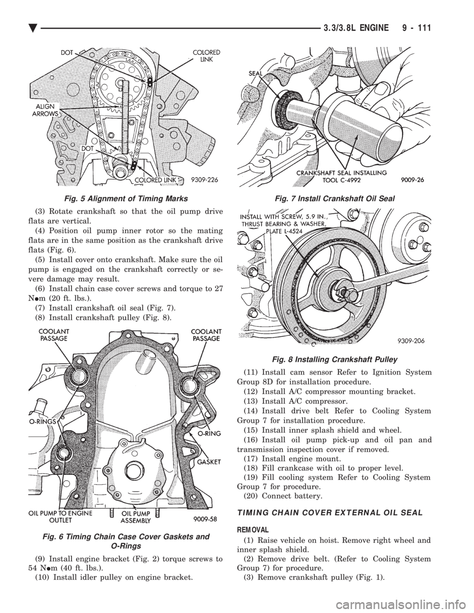
(3) Rotate crankshaft so that the oil pump drive
flats are vertical. (4) Position oil pump inner rotor so the mating
flats are in the same position as the crankshaft drive
flats (Fig. 6). (5) Install cover onto crankshaft. Make sure the oil
pump is engaged on the crankshaft correctly or se-
vere damage may result. (6) Install chain case cover screws and torque to 27
N Im (20 ft. lbs.).
(7) Install crankshaft oil seal (Fig. 7).
(8) Install crankshaft pulley (Fig. 8).
(9) Install engine bracket (Fig. 2) torque screws to
54 N Im (40 ft. lbs.).
(10) Install idler pulley on engine bracket. (11) Install cam sensor Refer to Ignition System
Group 8D for installation procedure. (12) Install A/C compressor mounting bracket.
(13) Install A/C compressor.
(14) Install drive belt Refer to Cooling System
Group 7 for installation procedure. (15) Install inner splash shield and wheel.
(16) Install oil pump pick-up and oil pan and
transmission inspection cover if removed. (17) Install engine mount.
(18) Fill crankcase with oil to proper level.
(19) Fill cooling system Refer to Cooling System
Group 7 for procedure. (20) Connect battery.
TIMING CHAIN COVER EXTERNAL OIL SEAL
REMOVAL
(1) Raise vehicle on hoist. Remove right wheel and
inner splash shield. (2) Remove drive belt. (Refer to Cooling System
Group 7) for procedure. (3) Remove crankshaft pulley (Fig. 1).
Fig. 5 Alignment of Timing Marks
Fig. 6 Timing Chain Case Cover Gaskets and O-Rings
Fig. 7 Install Crankshaft Oil Seal
Fig. 8 Installing Crankshaft Pulley
Ä 3.3/3.8L ENGINE 9 - 111
Page 1678 of 2438
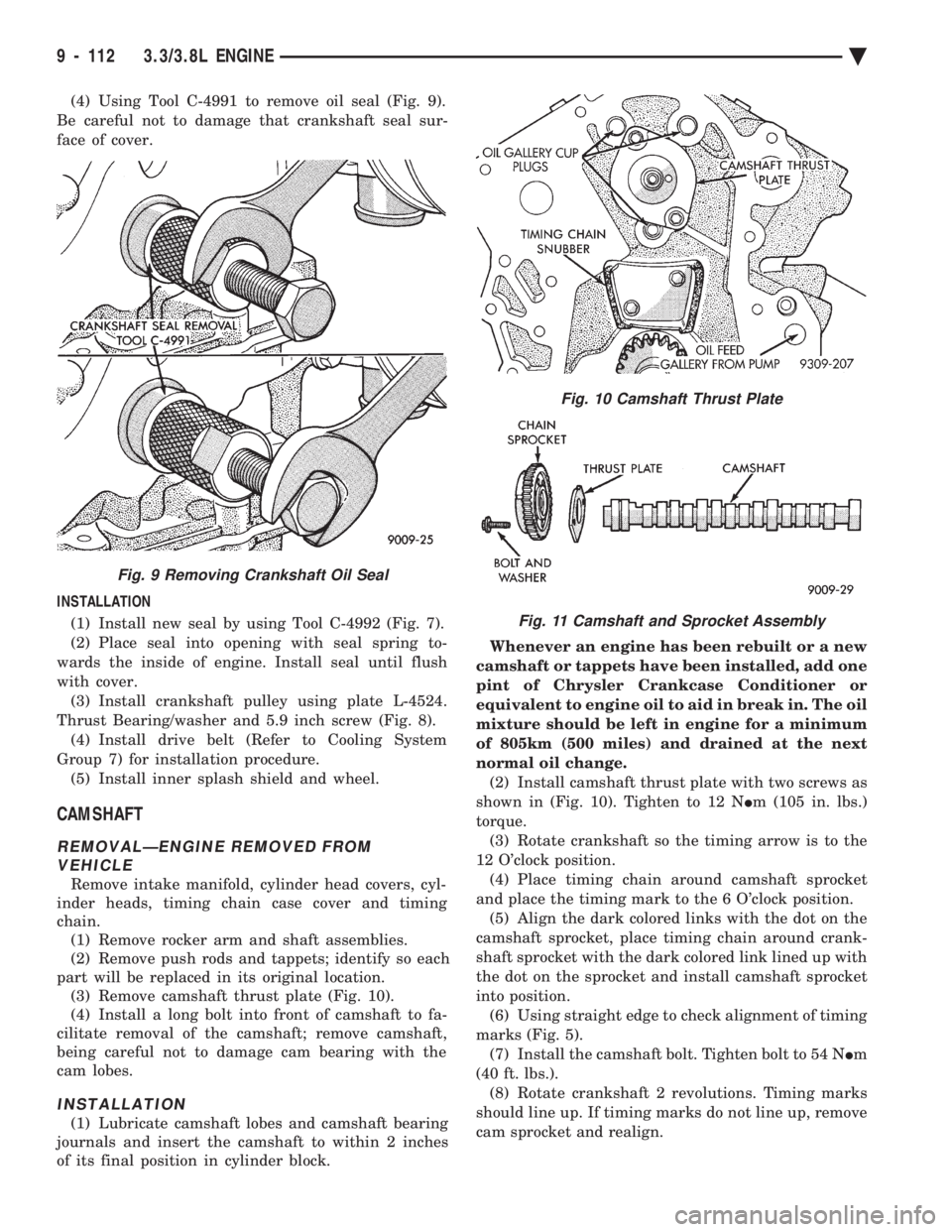
(4) Using Tool C-4991 to remove oil seal (Fig. 9).
Be careful not to damage that crankshaft seal sur-
face of cover.
INSTALLATION (1) Install new seal by using Tool C-4992 (Fig. 7).
(2) Place seal into opening with seal spring to-
wards the inside of engine. Install seal until flush
with cover. (3) Install crankshaft pulley using plate L-4524.
Thrust Bearing/washer and 5.9 inch screw (Fig. 8). (4) Install drive belt (Refer to Cooling System
Group 7) for installation procedure. (5) Install inner splash shield and wheel.
CAMSHAFT
REMOVALÐENGINE REMOVED FROM VEHICLE
Remove intake manifold, cylinder head covers, cyl-
inder heads, timing chain case cover and timing
chain. (1) Remove rocker arm and shaft assemblies.
(2) Remove push rods and tappets; identify so each
part will be replaced in its original location. (3) Remove camshaft thrust plate (Fig. 10).
(4) Install a long bolt into front of camshaft to fa-
cilitate removal of the camshaft; remove camshaft,
being careful not to damage cam bearing with the
cam lobes.
INSTALLATION
(1) Lubricate camshaft lobes and camshaft bearing
journals and insert the camshaft to within 2 inches
of its final position in cylinder block. Whenever an engine has been rebuilt or a new
camshaft or tappets have been installed, add one
pint of Chrysler Crankcase Conditioner or
equivalent to engine oil to aid in break in. The oil
mixture should be left in engine for a minimum
of 805km (500 miles) and drained at the next
normal oil change. (2) Install camshaft thrust plate with two screws as
shown in (Fig. 10). Tighten to 12 N Im (105 in. lbs.)
torque. (3) Rotate crankshaft so the timing arrow is to the
12 O'clock position. (4) Place timing chain around camshaft sprocket
and place the timing mark to the 6 O'clock position. (5) Align the dark colored links with the dot on the
camshaft sprocket, place timing chain around crank-
shaft sprocket with the dark colored link lined up with
the dot on the sprocket and install camshaft sprocket
into position. (6) Using straight edge to check alignment of timing
marks (Fig. 5). (7) Install the camshaft bolt. Tighten bolt to 54 N Im
(40 ft. lbs.). (8) Rotate crankshaft 2 revolutions. Timing marks
should line up. If timing marks do not line up, remove
cam sprocket and realign.
Fig. 9 Removing Crankshaft Oil Seal
Fig. 10 Camshaft Thrust Plate
Fig. 11 Camshaft and Sprocket Assembly
9 - 112 3.3/3.8L ENGINE Ä
Page 1708 of 2438
CAUTION: When using the ASD Fuel System Test,
the Auto Shutdown (ASD) relay will remain ener-
gized for 7 minutes or until the ignition switch is
turned to the OFF position, or Stop All Test is se-
lected.
TURBOCHARGER
REMOVAL
The turbocharger is removed from below the vehi-
cle. Cylinder head removal for component accessibil-
ity is not required. (1) Disconnect negative battery cable. Remove Air
Cleaner assembly (Fig. 1). (2) From Above: Remove front engine mount
through bolt and rotate engine (Top) forward away
from cowl. Refer to Engine Removal in Engine,
Group 9. (3) Remove Air Cleaner Support (Fig. 1).
(4) Disconnect Heated Oxygen sensor lead wire
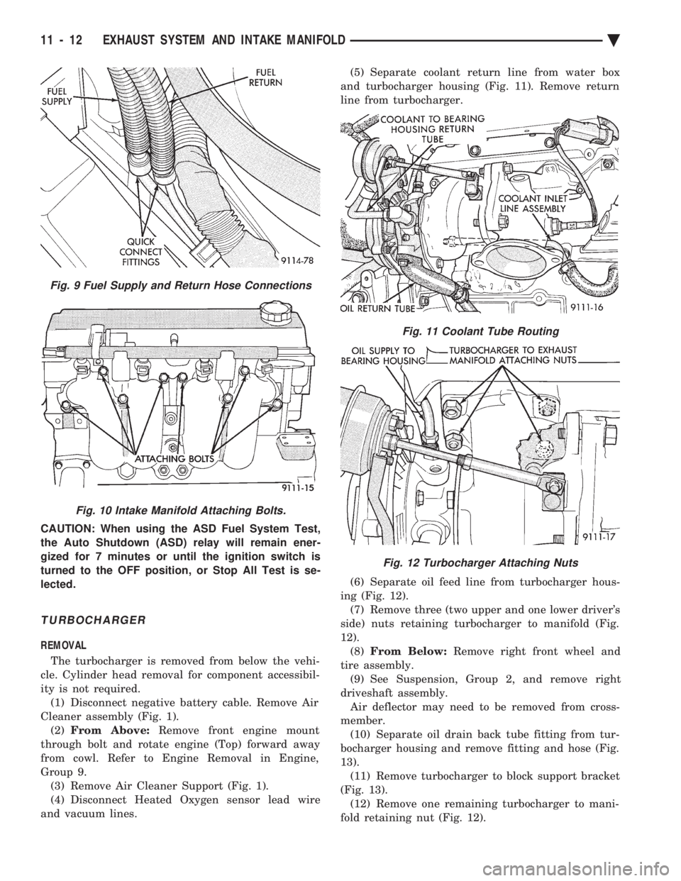
and vacuum lines. (5) Separate coolant return line from water box
and turbocharger housing (Fig. 11). Remove return
line from turbocharger.
(6) Separate oil feed line from turbocharger hous-
ing (Fig. 12). (7) Remove three (two upper and one lower driver's
side) nuts retaining turbocharger to manifold (Fig.
12). (8) From Below: Remove right front wheel and
tire assembly. (9) See Suspension, Group 2, and remove right
driveshaft assembly. Air deflector may need to be removed from cross-
member. (10) Separate oil drain back tube fitting from tur-
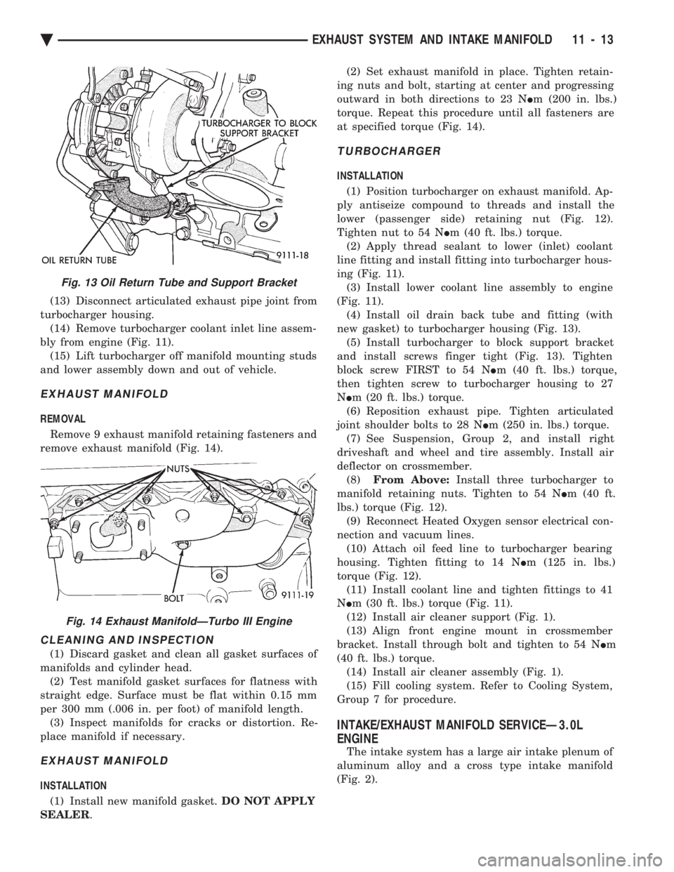
bocharger housing and remove fitting and hose (Fig.
13). (11) Remove turbocharger to block support bracket
(Fig. 13). (12) Remove one remaining turbocharger to mani-
fold retaining nut (Fig. 12).
Fig. 11 Coolant Tube Routing
Fig. 12 Turbocharger Attaching Nuts
Fig. 9 Fuel Supply and Return Hose Connections
Fig. 10 Intake Manifold Attaching Bolts.
11 - 12 EXHAUST SYSTEM AND INTAKE MANIFOLD Ä
Page 1709 of 2438
(13) Disconnect articulated exhaust pipe joint from
turbocharger housing. (14) Remove turbocharger coolant inlet line assem-
bly from engine (Fig. 11). (15) Lift turbocharger off manifold mounting studs
and lower assembly down and out of vehicle.
EXHAUST MANIFOLD
REMOVAL
Remove 9 exhaust manifold retaining fasteners and
remove exhaust manifold (Fig. 14).
CLEANING AND INSPECTION
(1) Discard gasket and clean all gasket surfaces of
manifolds and cylinder head. (2) Test manifold gasket surfaces for flatness with
straight edge. Surface must be flat within 0.15 mm
per 300 mm (.006 in. per foot) of manifold length. (3) Inspect manifolds for cracks or distortion. Re-
place manifold if necessary.
EXHAUST MANIFOLD
INSTALLATION
(1) Install new manifold gasket. DO NOT APPLY
SEALER . (2) Set exhaust manifold in place. Tighten retain-
ing nuts and bolt, starting at center and progressing
outward in both directions to 23 N Im (200 in. lbs.)
torque. Repeat this procedure until all fasteners are
at specified torque (Fig. 14).
TURBOCHARGER
INSTALLATION
(1) Position turbocharger on exhaust manifold. Ap-
ply antiseize compound to threads and install the
lower (passenger side) retaining nut (Fig. 12).
Tighten nut to 54 N Im (40 ft. lbs.) torque.
(2) Apply thread sealant to lower (inlet) coolant
line fitting and install fitting into turbocharger hous-
ing (Fig. 11). (3) Install lower coolant line assembly to engine
(Fig. 11). (4) Install oil drain back tube and fitting (with
new gasket) to turbocharger housing (Fig. 13). (5) Install turbocharger to block support bracket
and install screws finger tight (Fig. 13). Tighten
block screw FIRST to 54 N Im (40 ft. lbs.) torque,
then tighten screw to turbocharger housing to 27
N Im (20 ft. lbs.) torque.
(6) Reposition exhaust pipe. Tighten articulated
joint shoulder bolts to 28 N Im (250 in. lbs.) torque.
(7) See Suspension, Group 2, and install right
driveshaft and wheel and tire assembly. Install air
deflector on crossmember. (8) From Above: Install three turbocharger to
manifold retaining nuts. Tighten to 54 N Im (40 ft.
lbs.) torque (Fig. 12). (9) Reconnect Heated Oxygen sensor electrical con-
nection and vacuum lines. (10) Attach oil feed line to turbocharger bearing
housing. Tighten fitting to 14 N Im (125 in. lbs.)
torque (Fig. 12). (11) Install coolant line and tighten fittings to 41
N Im (30 ft. lbs.) torque (Fig. 11).
(12) Install air cleaner support (Fig. 1).
(13) Align front engine mount in crossmember
bracket. Install through bolt and tighten to 54 N Im
(40 ft. lbs.) torque. (14) Install air cleaner assembly (Fig. 1).
(15) Fill cooling system. Refer to Cooling System,
Group 7 for procedure.
INTAKE/EXHAUST MANIFOLD SERVICEÐ3.0L
ENGINE
The intake system has a large air intake plenum of
aluminum alloy and a cross type intake manifold
(Fig. 2).
Fig. 13 Oil Return Tube and Support Bracket
Fig. 14 Exhaust ManifoldÐTurbo III Engine
Ä EXHAUST SYSTEM AND INTAKE MANIFOLD 11 - 13
Page 1724 of 2438
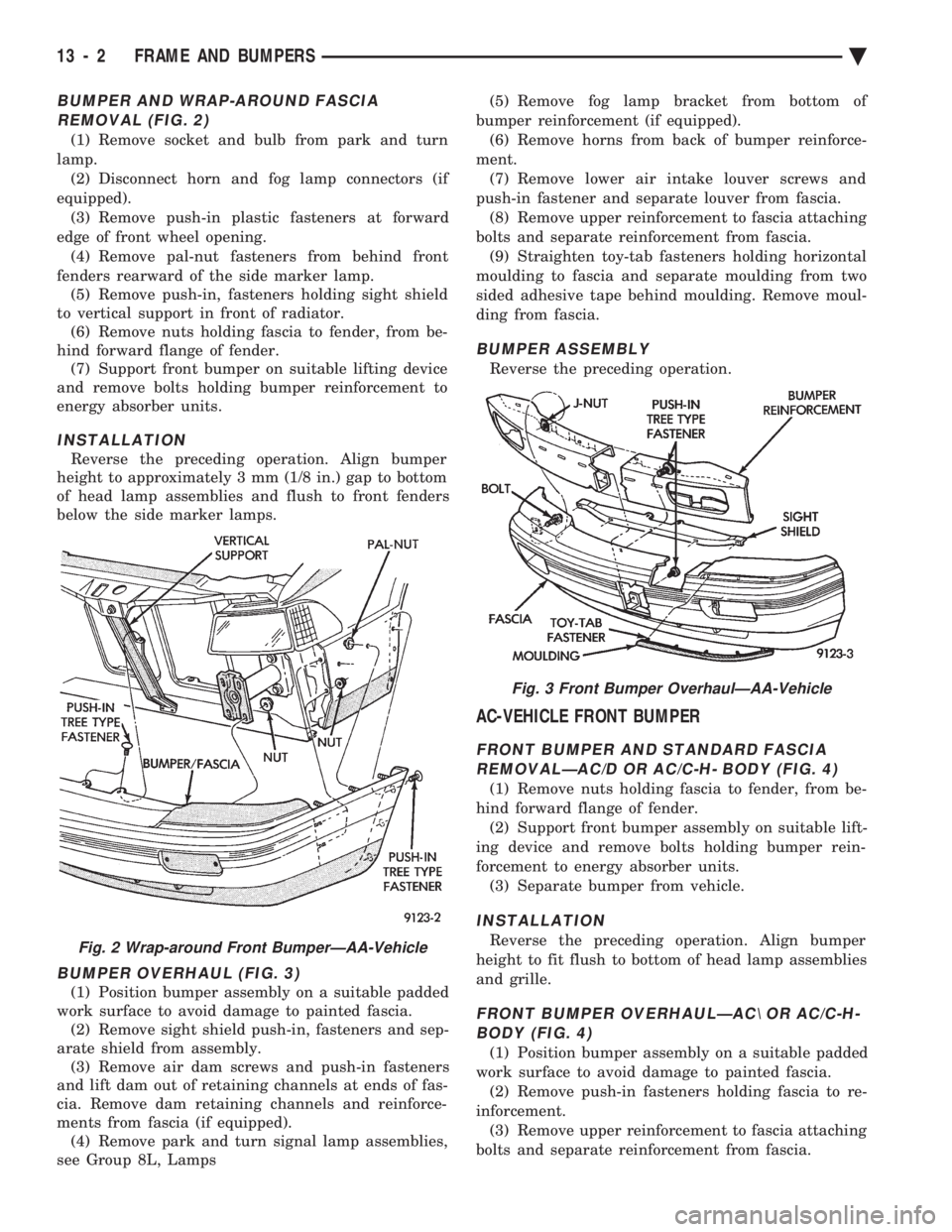
BUMPER AND WRAP-AROUND FASCIA REMOVAL (FIG. 2)
(1) Remove socket and bulb from park and turn
lamp. (2) Disconnect horn and fog lamp connectors (if
equipped). (3) Remove push-in plastic fasteners at forward
edge of front wheel opening. (4) Remove pal-nut fasteners from behind front
fenders rearward of the side marker lamp. (5) Remove push-in, fasteners holding sight shield
to vertical support in front of radiator. (6) Remove nuts holding fascia to fender, from be-
hind forward flange of fender. (7) Support front bumper on suitable lifting device
and remove bolts holding bumper reinforcement to
energy absorber units.
INSTALLATION
Reverse the preceding operation. Align bumper
height to approximately 3 mm (1/8 in.) gap to bottom
of head lamp assemblies and flush to front fenders
below the side marker lamps.
BUMPER OVERHAUL (FIG. 3)
(1) Position bumper assembly on a suitable padded
work surface to avoid damage to painted fascia. (2) Remove sight shield push-in, fasteners and sep-
arate shield from assembly. (3) Remove air dam screws and push-in fasteners
and lift dam out of retaining channels at ends of fas-
cia. Remove dam retaining channels and reinforce-
ments from fascia (if equipped). (4) Remove park and turn signal lamp assemblies,
see Group 8L, Lamps (5) Remove fog lamp bracket from bottom of
bumper reinforcement (if equipped). (6) Remove horns from back of bumper reinforce-
ment. (7) Remove lower air intake louver screws and
push-in fastener and separate louver from fascia. (8) Remove upper reinforcement to fascia attaching
bolts and separate reinforcement from fascia. (9) Straighten toy-tab fasteners holding horizontal
moulding to fascia and separate moulding from two
sided adhesive tape behind moulding. Remove moul-
ding from fascia.
BUMPER ASSEMBLY
Reverse the preceding operation.
AC-VEHICLE FRONT BUMPER
FRONT BUMPER AND STANDARD FASCIA REMOVALÐAC/D OR AC/C-H- BODY (FIG. 4)
(1) Remove nuts holding fascia to fender, from be-
hind forward flange of fender. (2) Support front bumper assembly on suitable lift-
ing device and remove bolts holding bumper rein-
forcement to energy absorber units. (3) Separate bumper from vehicle.
INSTALLATION
Reverse the preceding operation. Align bumper
height to fit flush to bottom of head lamp assemblies
and grille.
FRONT BUMPER OVERHAULÐAC\ OR AC/C-H- BODY (FIG. 4)
(1) Position bumper assembly on a suitable padded
work surface to avoid damage to painted fascia. (2) Remove push-in fasteners holding fascia to re-
inforcement. (3) Remove upper reinforcement to fascia attaching
bolts and separate reinforcement from fascia.
Fig. 2 Wrap-around Front BumperÐAA-Vehicle
Fig. 3 Front Bumper OverhaulÐAA-Vehicle
13 - 2 FRAME AND BUMPERS Ä
Page 1725 of 2438
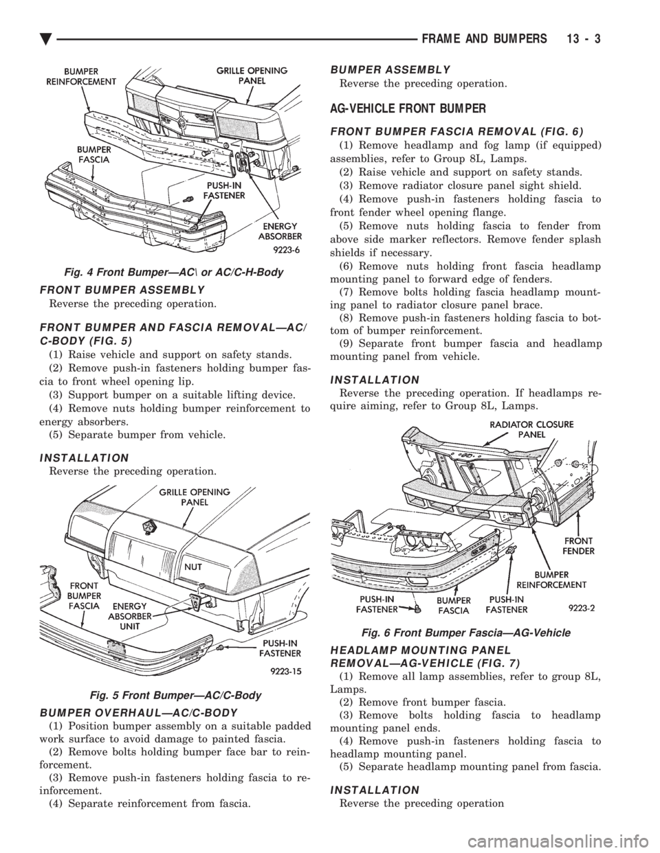
FRONT BUMPER ASSEMBLY
Reverse the preceding operation.
FRONT BUMPER AND FASCIA REMOVALÐAC/ C-BODY (FIG. 5)
(1) Raise vehicle and support on safety stands.
(2) Remove push-in fasteners holding bumper fas-
cia to front wheel opening lip. (3) Support bumper on a suitable lifting device.
(4) Remove nuts holding bumper reinforcement to
energy absorbers. (5) Separate bumper from vehicle.
INSTALLATION
Reverse the preceding operation.
BUMPER OVERHAULÐAC/C-BODY
(1) Position bumper assembly on a suitable padded
work surface to avoid damage to painted fascia. (2) Remove bolts holding bumper face bar to rein-
forcement. (3) Remove push-in fasteners holding fascia to re-
inforcement. (4) Separate reinforcement from fascia.
BUMPER ASSEMBLY
Reverse the preceding operation.
AG-VEHICLE FRONT BUMPER
FRONT BUMPER FASCIA REMOVAL (FIG. 6)
(1) Remove headlamp and fog lamp (if equipped)
assemblies, refer to Group 8L, Lamps. (2) Raise vehicle and support on safety stands.
(3) Remove radiator closure panel sight shield.
(4) Remove push-in fasteners holding fascia to
front fender wheel opening flange. (5) Remove nuts holding fascia to fender from
above side marker reflectors. Remove fender splash
shields if necessary. (6) Remove nuts holding front fascia headlamp
mounting panel to forward edge of fenders. (7) Remove bolts holding fascia headlamp mount-
ing panel to radiator closure panel brace. (8) Remove push-in fasteners holding fascia to bot-
tom of bumper reinforcement. (9) Separate front bumper fascia and headlamp
mounting panel from vehicle.
INSTALLATION
Reverse the preceding operation. If headlamps re-
quire aiming, refer to Group 8L, Lamps.
HEADLAMP MOUNTING PANEL REMOVALÐAG-VEHICLE (FIG. 7)
(1) Remove all lamp assemblies, refer to group 8L,
Lamps. (2) Remove front bumper fascia.
(3) Remove bolts holding fascia to headlamp
mounting panel ends. (4) Remove push-in fasteners holding fascia to
headlamp mounting panel. (5) Separate headlamp mounting panel from fascia.
INSTALLATION
Reverse the preceding operation
Fig. 4 Front BumperÐAC\ or AC/C-H-Body
Fig. 5 Front BumperÐAC/C-Body
Fig. 6 Front Bumper FasciaÐAG-Vehicle
Ä FRAME AND BUMPERS 13 - 3
Page 1726 of 2438
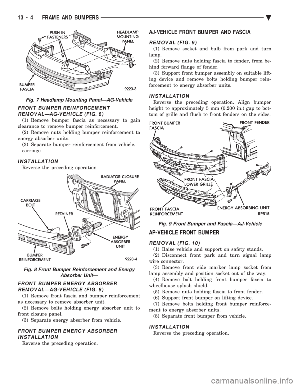
FRONT BUMPER REINFORCEMENT REMOVALÐAG-VEHICLE (FIG. 8)
(1) Remove bumper fascia as necessary to gain
clearance to remove bumper reinforcement. (2) Remove nuts holding bumper reinforcement to
energy absorber units. (3) Separate bumper reinforcement from vehicle.
carriage
INSTALLATION
Reverse the preceding operation
FRONT BUMPER ENERGY ABSORBERREMOVALÐAG-VEHICLE (FIG. 8)
(1) Remove front fascia and bumper reinforcement
as necessary to remove absorber unit. (2) Remove bolts holding energy absorber unit to
front closure panel. (3) Separate energy absorber from vehicle.
FRONT BUMPER ENERGY ABSORBERINSTALLATION
Reverse the preceding operation.
AJ-VEHICLE FRONT BUMPER AND FASCIA
REMOVAL (FIG. 9)
(1) Remove socket and bulb from park and turn
lamp. (2) Remove nuts holding fascia to fender, from be-
hind forward flange of fender. (3) Support front bumper assembly on suitable lift-
ing device and remove bolts holding bumper rein-
forcement to energy absorber units.
INSTALLATION
Reverse the preceding operation. Align bumper
height to approximately 5 mm (0.200 in.) gap to bot-
tom of grille and flush to front fenders on the sides.
AP-VEHICLE FRONT BUMPER
REMOVAL (FIG. 10)
(1) Raise vehicle and support on safety stands.
(2) Disconnect front park and turn signal lamp
wire connector. (3) Remove front side marker lamp socket from
lamp assembly and position socket out of the way. (4) Remove bolt holding front bumper fascia to
wheelhouse splash shield. (5) Remove nuts holding fascia to front fender.
(6) Support front bumper on lifting device.
(7) Remove bolts holding front bumper reinforce-
ment to energy absorber units. (8) Separate front bumper from vehicle.
INSTALLATION
Reverse the preceding operation.
Fig. 7 Headlamp Mounting PanelÐAG-Vehicle
Fig. 8 Front Bumper Reinforcement and Energy Absorber UnitÐ
Fig. 9 Front Bumper and FasciaÐAJ-Vehicle
13 - 4 FRAME AND BUMPERS Ä
Page 1727 of 2438
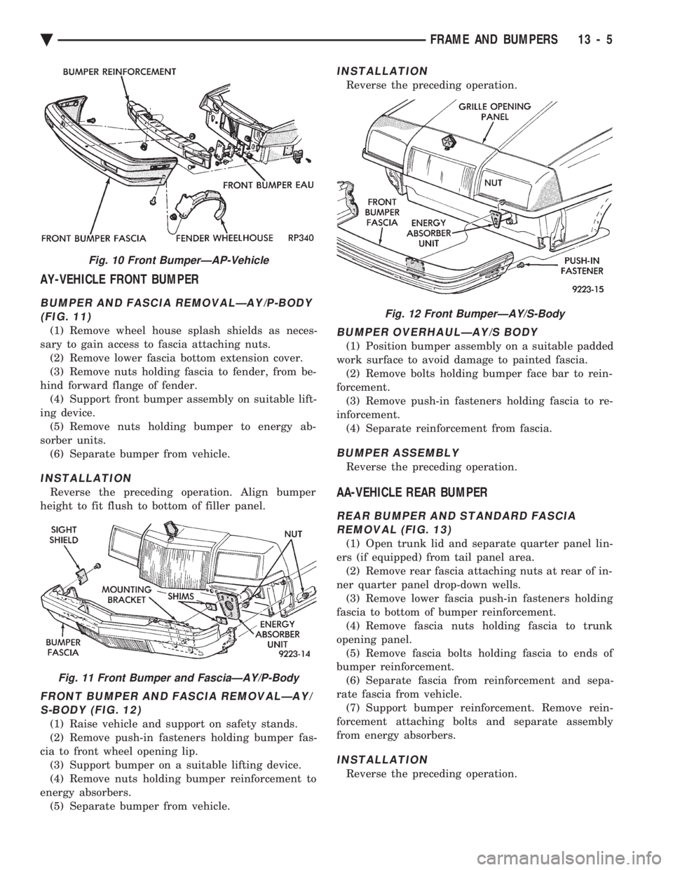
AY-VEHICLE FRONT BUMPER
BUMPER AND FASCIA REMOVALÐAY/P-BODY (FIG. 11)
(1) Remove wheel house splash shields as neces-
sary to gain access to fascia attaching nuts. (2) Remove lower fascia bottom extension cover.
(3) Remove nuts holding fascia to fender, from be-
hind forward flange of fender. (4) Support front bumper assembly on suitable lift-
ing device. (5) Remove nuts holding bumper to energy ab-
sorber units. (6) Separate bumper from vehicle.
INSTALLATION
Reverse the preceding operation. Align bumper
height to fit flush to bottom of filler panel.
FRONT BUMPER AND FASCIA REMOVALÐAY/ S-BODY (FIG. 12)
(1) Raise vehicle and support on safety stands.
(2) Remove push-in fasteners holding bumper fas-
cia to front wheel opening lip. (3) Support bumper on a suitable lifting device.
(4) Remove nuts holding bumper reinforcement to
energy absorbers. (5) Separate bumper from vehicle.
INSTALLATION
Reverse the preceding operation.
BUMPER OVERHAULÐAY/S BODY
(1) Position bumper assembly on a suitable padded
work surface to avoid damage to painted fascia. (2) Remove bolts holding bumper face bar to rein-
forcement. (3) Remove push-in fasteners holding fascia to re-
inforcement. (4) Separate reinforcement from fascia.
BUMPER ASSEMBLY
Reverse the preceding operation.
AA-VEHICLE REAR BUMPER
REAR BUMPER AND STANDARD FASCIAREMOVAL (FIG. 13)
(1) Open trunk lid and separate quarter panel lin-
ers (if equipped) from tail panel area. (2) Remove rear fascia attaching nuts at rear of in-
ner quarter panel drop-down wells. (3) Remove lower fascia push-in fasteners holding
fascia to bottom of bumper reinforcement. (4) Remove fascia nuts holding fascia to trunk
opening panel. (5) Remove fascia bolts holding fascia to ends of
bumper reinforcement. (6) Separate fascia from reinforcement and sepa-
rate fascia from vehicle. (7) Support bumper reinforcement. Remove rein-
forcement attaching bolts and separate assembly
from energy absorbers.
INSTALLATION
Reverse the preceding operation.
Fig. 10 Front BumperÐAP-Vehicle
Fig. 11 Front Bumper and FasciaÐAY/P-Body
Fig. 12 Front BumperÐAY/S-Body
Ä FRAME AND BUMPERS 13 - 5