1993 CHEVROLET DYNASTY wheel
[x] Cancel search: wheelPage 1811 of 2438
the PCM to store diagnostic trouble codes for other
systems. For example, a fuel pressure problem will not
register a fault directly, but could cause a rich or lean
condition. This could cause the PCM to store an oxygen
sensor diagnostic trouble code. Fuel Pressure - The vacuum assisted fuel pressure
regulator controls fuel system pressure. The PCM
cannot detect a clogged fuel pump inlet filter, clogged
in-line fuel filter, stuck open regulator, or a pinched
fuel supply or return line. However, these could result
in a rich or lean condition causing the PCM to store an
oxygen sensor diagnostic trouble code. Secondary Ignition Circuit - The PCM cannot
detect an inoperative ignition coil, fouled or worn spark
plugs, ignition cross firing, or open spark plug cables. Engine Timing - The PCM cannot detect an incor-
rectly indexed timing belt, camshaft sprocket and
crankshaft sprocket. However, these could result in a
rich or lean condition causing the PCM to store an
oxygen sensor diagnostic trouble code. Cylinder Compression - The PCM cannot detect
uneven, low, or high engine cylinder compression. Exhaust System - The PCM cannot detect a
plugged, restricted or leaking exhaust system. Fuel Injector Mechanical Malfunctions - The
PCM cannot determine if a fuel injector is clogged, the
needle is sticking or if the wrong injector is installed.
However, these could result in a rich or lean condition
causing the PCM to store an oxygen sensor diagnostic
trouble code. Excessive Oil Consumption - Although the PCM
monitors exhaust stream oxygen content when the
system is in closed loop, it cannot determine excessive
oil consumption. Throttle Body Air Flow - The PCM cannot detect a
clogged or restricted air cleaner inlet or filter element. Evaporative System - The PCM cannot detect a
disconnected (open vacuum line) restricted, plugged or
loaded evaporative purge canister. Vacuum Assist - The PCM cannot detect leaks or
restrictions in the vacuum circuits of vacuum assisted
engine control system devices. However, these could
cause the PCM to store a MAP sensor diagnostic
trouble code and cause a high idle condition. PCM System Ground - The PCM cannot determine
a poor system ground. However, one or more diagnostic
trouble codes may be generated as a result of this
condition. PCM Connector Engagement - The PCM may not
be able to determine spread or damaged connector
pins. However, it might store diagnostic trouble codes
as a result of spread connector pins.HIGH AND LOW LIMITS
The PCM compares input signal voltages from each
input device with established high and low limits for the
device. If the input voltage is not within limits and other
criteria are met, the PCM stores a diagnostic trouble code
in memory. Other diagnostic trouble code criteria might
include engine RPM limits or input voltages from other
sensors or switches that must be present before verifying
a diagnostic trouble code condition.
DIAGNOSTIC TROUBLE CODES
A diagnostic trouble code indicates the powertrain
control module (PCM) has recognized an abnormal
condition in the system. Abnormal conditions are usu-
ally shorted or open circuits.
The technician can display diagnostic trouble codes in
two ways. The first way is to cycle the ignition switch and
count the number of times the malfunction indicator lamp
(check engine lamp on the instrument panel) flashes on
and off. The DRBII scan tool provides the second method
of displaying diagnostic trouble codes. Diagnostic trouble
codes indicate the results of a circuit failure, but do not
directly identify the failed component.
For a list of Diagnostic Trouble Codes, refer to
the charts at the end of this section.
OBTAINING DIAGNOSTIC TROUBLE CODES
USING DRBII SCAN TOOL
WARNING: APPLY PARKING BRAKE AND/OR BLOCK
WHEELS BEFORE PERFORMING ANY TEST ON AN
OPERATING ENGINE. (1) Connect DRBII scan tool to the data link (diag-
nostic) connector located in the engine compartment,
next to the PCM (Fig. 1). (2) If possible, start the engine and cycle the A/C
switch if applicable. Shut off the engine. (3)
Turn the ignition switch on, access Read Fault
Screen. Record all the diagnostic trouble codes shown on
the DRBII scan tool. [Observe the malfunction indicator
lamp (check engine lamp) on the instrument panel. The
lamp should light for 2 seconds then go out (bulb check)].
To erase diagnostic trouble codes, use the Erase
Trouble Code data screen on the DRBII scan tool.
USING THE MALFUNCTION INDICATOR LAMP (1) Cycle the ignition key On - Off - On - Off - On
within 5 seconds. (2) Count the number of times the malfunction indi-
cator lamp (check engine lamp on the instrument
panel) flashes on and off. The number of flashes
represents the trouble code. There is a slight pause be-
Ä FUEL SYSTEMS 14 - 71
Page 1827 of 2438
CRANKSHAFT POSITION SENSORÐPCM INPUT
The crankshaft position sensor (Fig. 8) senses slots
cut into the flywheel. There ar e a 2 sets of slots.
Each set contains 4 slots, for a total of 8 slots (Fig.
9). Basic timing is set by the position of the last slot
in each group. Once the PCM senses the last slot, it
determines crankshaft position (which piston will
next be at TDC) from the camshaft position sensor
input. The 4 pulses generated by the crankshaft po-
sition sensor represent the 69É, 49É, 29É, and 9É BTDC
marks. It may take the PCM one engine revolution
to determine crankshaft position. The Turbo III en-
gine uses a fixed ignition system. Base timing is not
adjustable.
The PCM uses the crankshaft position sensor input
to determine injector sequence and ignition timing.
Once crankshaft position has been determined, the
PCM begins energizing the injectors in sequence. The crankshaft position sensor is located in the
transaxle housing, below the throttle body (Fig. 10).
The bottom of the sensor is positioned next to the
drive plate. The distance between the bottom of sensor and the drive plate is critical to the oper-
ation of the system. When servicing the crank-
shaft position sensor, refer to the 2.2L Turbo III
Multi-Port Fuel InjectionÐService Procedures
section in this Group.
KNOCK SENSORÐPCM INPUT
The knock sensor generates a signal when spark
knock occurs in the combustion chambers. The sensor
can detect detonation in the cylinders. The sensor
provides information used by the PCM to modify
spark advance and boost schedules in order to elimi-
nate detonation. The knock sensor is installed into the engine, be-
hind the PCV breather/separator (Fig. 11).
MANIFOLD ABSOLUTE PRESSURE (MAP)
SENSORÐPCM INPUT
The PCM supplies 5 volts to the MAP sensor. The
Map sensor converts intake manifold pressure into
voltage. The PCM monitors the MAP sensor output
voltage. As vacuum increases, MAP sensor voltage
decreases proportionately. Also, as vacuum decreases,
MAP sensor voltage increases proportionately.
Fig. 7 Coolant Temperature Sensor
Fig. 8 Crankshaft Position Sensor
Fig. 9 Timing Slots
Fig. 10 Crankshaft Position Sensor Location
Ä FUEL SYSTEMS 14 - 87
Page 1844 of 2438
SYSTEM TESTS
Apply parking brake and/or block wheels be-
fore performing idle check or adjustment, or any
engine running tests.
OBTAINING DIAGNOSTIC TROUBLE CODES
(1) Connect DRBII scan tool to the data link connec-
tor (Fig. 1). (2) Start the engine if possible, cycle the trans mis-
sion selector and the A/Cswitch if applicable. Shut off
the engine. (3) Turn the ignition switch on, access Read Fault
Screen. Record all the fault messages shown on the
DRBII scan tool. Observe the malfunction indicator
lamp (check engine lamp on the instrument panel). The
lamp should light for 2 seconds then go out (bulb
check). Diagnostic trouble code erasure: access erase
diagnostic trouble code data.
STATE DISPLAY TEST MODE
The switch inputs used by the powertrain control
module (PCM) have only two recognized states, HIGH
and LOW. For this reason, the PCM cannot recognize
the difference between a selected switch position ver-
sus an open circuit, a short circuit, or a defective
switch. If the display changes, assume the entire
switch circuit to the PCM is functional. From the state
display screen access either State Display Inputs and
Outputs or State Display Sensors.
STATE DISPLAY INPUTS AND OUTPUTS
Connect the DRBII scan tool to the vehicle and access
the State Display screen. Then access Inputs and
Outputs. The following is a list of the engine control
system functions accessible through the Inputs and
Outputs screen. Speed Control Resume
Brake Switch
Speed Control On/Off
Speed Control Set
A/C Switch Sense
S/C Vent Solenoid S/C Vacuum Solenoid
A/C Clutch Relay
Baro Read Solenoid
Wastegate Solenoid
Auto Shutdown Relay
Radiator Fan Relay
Purge Solenoid
Malfunction Indicator Lamp (Check Engine Lamp)
STATE DISPLAY SENSORS
Connect the DRBII scan tool to the vehicle and ac-
cess the State Display screen. Then access Sensor
Display. The following is a list of the engine control
system functions accessible through the Sensor Dis-
play screen. Oxygen Sensor Signal
Coolant Temperature
Coolant Temp Sensor
Throttle Position
Minimum Throttle
Knock Sensor Signal
Battery Voltage
MAP Sensor Reading
Idle Air Control Motor Position
Adaptive Fuel Factor
Barometric Pressure
Min Airflow Idle Spd (speed)
Engine Speed
DIS Sensor Status
Fault #1 Key-On Info
Module Spark Advance
Cyl 1 Knock Retard
Cyl 2 Knock Retard
Cyl 3 Knock Retard
Cyl 4 Knock Retard
Boost Pressure Goal
Charge Temperature
Charge Temp Sensor
Speed Control Target
Fault #2 Key-on Info
Fault #3 Key-on Info
Speed Control Status
Charging System Goal
Theft Alarm Status
DIAGNOSTIC TROUBLE CODE DESCRIPTION (CON'T)
14 - 104 FUEL SYSTEMS Ä
Page 1874 of 2438
SYSTEM TESTS
WARNING: APPLY PARKING BRAKE AND/OR BLOCK
WHEELS BEFORE PERFORMING ANY TEST ON AN
OPERATING ENGINE.
OBTAINING DIAGNOSTIC TROUBLE CODES
(1) Connect DRBII scan tool to the data link connec-
tor located in the engine compartment near the pow-
ertrain control module (PCM). (2) Start the engine if possible, cycle the transaxle
selector and the A/Cswitch if applicable. Shut off the
engine. (3) Turn the ignition switch on, access Read Fault
Screen. Record all the fault messages shown on the
DRBII scan tool. Observe the malfunction indicator
lamp (Check Engine lamp on the instrument panel).
The lamp should light for 3 seconds then go out (bulb
check). Diagnostic trouble code erasure; access erase
diagnostic trouble code data
STATE DISPLAY TEST MODE
The switch inputs used by the powertrain control
module (PCM) have only two recognized states, HIGH
and LOW. For this reason, the PCM cannot recognize
the difference between a selected switch position ver-
sus an open circuit, a short circuit, or a defective
switch. If the change is displayed, it can be assumed
that the entire switch circuit to the PCM is functional.
From the state display screen access either State
Display Inputs and Outputs or State Display Sensors.
STATE DISPLAY INPUTS AND OUTPUTS
Connect the DRBII scan tool to the vehicle. Access
the State Display screen. Then access Inputs and
Outputs. The following is a list of the engine control
system functions accessible through the Inputs and
Outputs screen. Park/Neutral Switch
Speed Control Resume
Brake Switch
Speed Control On/Off
Speed Control Set
A/C Switch Sense
S/C Vent Solenoid
S/C Vacuum Solenoid
A/C Clutch Relay
EGR Solenoid
Auto Shutdown Relay
Radiator Fan Relay
Purge Solenoid
Torque Converter Clutch Solenoid
Malfunction Indicator Lamp (Check Engine Lamp)
STATE DISPLAY SENSORS
Connect the DRBII scan tool to the vehicle and ac-
cess the State Display screen. Then access Sensor
Display. The following is a list of the engine control
system functions accessible through the Sensor Dis-
play screen. Battery Temperature
Oxygen Sensor Signal
Engine Coolant Temperature
Engine Coolant Temp Sensor
Throttle Position
Minimum Throttle
Battery Voltage
MAP Sensor Reading
Idle Air Control Motor Position
Adaptive Fuel Factor
Barometric Pressure
Min Airflow Idle Speed
Engine Speed
Fault #1 Key-On Info
Module Spark Advance
Speed Control Target
Fault #2 Key-on Info
Fault #3 Key-on Info
Speed Control Status
Speed Control Switch Voltage
Charging System Goal
Theft Alarm Status
Map Sensor Voltage
Vehicle Speed
Oxygen Sensor State
MAP Gauge Reading
Throttle Opening (percentage)
Total Spark Advance
CIRCUIT ACTUATION TEST MODE
The circuit actuation test mode checks for proper
operation of output circuits or devices which the pow-
ertrain control module (PCM) cannot internally rec-
ognize. The PCM can attempt to activate these
outputs and allow an observer to verify proper oper-
ation. Most of the tests provide an audible or visual
indication of device operation (click of relay contacts,
spray fuel, etc.). Except for intermittent conditions, if
a device functions properly during testing, assume
the device, its associated wiring, and driver circuit
working correctly.
OBTAINING CIRCUIT ACTUATION TEST
Connect the DRBII scan tool to the vehicle and ac-
cess the Actuators screen. The following is a list of
the engine control system functions accessible
through Actuators screens. Stop All Tests
Ignition Coil #1
Fuel Injector #1
Fuel Injector #2
Fuel Injector #3
14 - 134 FUEL SYSTEMS Ä
Page 1903 of 2438
line. However, these could result in a rich or lean
condition causing an oxygen sensor fault to be stored in
the PCM. Secondary Ignition Circuit - The PCM cannot
detect an inoperative ignition coil, fouled or worn spark
plugs, ignition cross firing, or open spark plug cables. Engine Timing - The PCM cannot detect an incor-
rectly indexed timing chain, camshaft sprocket and
crankshaft sprocket. However, these could result in a
rich or lean condition causing an oxygen sensor fault to
be stored in the PCM. Cylinder Compression - The PCM cannot detect
uneven, low, or high engine cylinder compression. Exhaust System - The PCM cannot detect a
plugged, restricted or leaking exhaust system. Fuel Injector Malfunctions - The PCM cannot
determine if a fuel injector is clogged, the needle is
sticking or the wrong injector is installed. However,
these could result in a rich or lean condition causing an
oxygen sensor fault to be stored in the PCM. Excessive Oil Consumption - Although the PCM
monitors exhaust stream oxygen content when the
system is in closed loop, it cannot determine excessive
oil consumption. Throttle Body Air Flow - The PCM cannot detect a
clogged or restricted air cleaner inlet or filter element. Evaporative System - The PCM will not detect a
restricted, plugged or loaded evaporative purge canis-
ter. Vacuum Assist - Leaks or restrictions in the
vacuum circuits of vacuum assisted engine control
system devices are not monitored by the PCM. How-
ever, these could result in a MAP sensor fault being
stored in the PCM. PCM System Ground - The PCM cannot determine
a poor system ground. However, a diagnostic trouble
code may be generated as a result of this condition. PCM Connector Engagement - The PCM cannot
determine spread or damaged connector pins. How-
ever, a diagnostic trouble code may be generated as a
result of this condition.
HIGH AND LOW LIMITS
The powertrain control module (PCM) compares in-
put signal voltages from each input device with estab-
lished high and low limits for the device. If the input
voltage is not within limits and other diagnostic
trouble code criteria are met, a diagnostic trouble code
will be stored in memory. Other diagnostic trouble code
criteria might include engine RPM limits or input
voltages from other sensors or switches that must be
present before a fault condition can be verified.
DIAGNOSTIC TROUBLE CODE DESCRIPTION
A diagnostic trouble code indicates that the power-
train control module (PCM) has recognized an abnor- mal condition in the system. Diagnostic trouble codes
can be obtained from the malfunction indicator lamp
(Check Engine lamp on the instrument panel) or from
the DRBII scan tool. Diagnostic trouble codes indicate
the results of a failure but do not identify the failed
component directly.
SYSTEM TESTS
WARNING: APPLY PARKING BRAKE AND/OR BLOCK
WHEELS BEFORE PERFORMING ANY TEST ON AN
OPERATING ENGINE.
OBTAINING DIAGNOSTIC TROUBLE CODES
(1) Connect the DRBII scan tool to the data link
connector located in the engine compartment near the
driver side strut tower (Fig. 1). (2) Start the engine if possible, cycle the transaxle
selector and the A/Cswitch if applicable. Shut off the
engine. (3) Turn the ignition switch on, access Read Fault
Screen. Record all the fault messages shown on the
DRBII scan tool. Observe the malfunction indicator
lamp (check engine lamp on the instrument panel). The
lamp should light for 2 seconds then go out (bulb
check). Diagnostic trouble code erasure; access erase
diagnostic trouble code data
STATE DISPLAY TEST MODE
The switch inputs used by the powertrain control
module (PCM) have only two recognized states, HIGH
and LOW. For this reason, the PCM cannot recognize
the difference between a selected switch position ver-
sus an open circuit, a short circuit, or a defective
switch. If the change is displayed, it can be assumed
that the entire switch circuit to the PCM is functional.
From the state display screen access either State
Display Inputs and Outputs or State Display Sensors.
STATE DISPLAY INPUTS AND OUTPUTS
Connect the DRBII scan tool to the vehicle and access
the State Display screen. Then access Inputs and
Outputs. The following is a list of the engine control
system functions accessible through the Inputs and
Outputs screen. Park/Neutral Switch
Speed Control Resume
Brake Switch
Speed Control On/Off
Speed Control Set
A/C Switch Sense
S/C Vent Solenoid
Ä FUEL SYSTEMS 14 - 163
Page 1919 of 2438
STEERING
CONTENTS
page page
ACUSTAR STANDARD AND TILT STEERING COLUMN ............................ 28
AUTOMATIC TRANSMISSION SHIFTER/IGNITION INTERLOCK .......................... 36
GENERAL INFORMATION .................. 1 POWER STEERING GEAR
................ 25
POWER STEERING PUMPS ................ 1
SPECIFICATIONS AND TIGHTENING REFERENCE .......................... 42
GENERAL INFORMATION
Safety goggles should be worn at all times
when working on any steering gear or pump. Throughout this group, references may be made to
a particular vehicle by letter or number designation.
A chart showing the breakdown of these designations
is included in the Introduction Section at the front of
this service manual. The power steering system consists of these four
major components. Power Steering Pump, Power
Steering Gear, Pressure Hose, and Return Line.
Turning of the steering wheel is converted into lin-
ear travel through the meshing of the helical pinion teeth with the rack teeth. Power assist steering is
provided by an open center, rotary type control valve.
It is used to direct oil from the power steering pump
to either side of the integral steering rack piston. Road feel is controlled by the diameter of a torsion
bar which initially steers the vehicle. As steering ef-
fort increases as in a turn, the torsion bar twists,
causing relative rotary motion between the rotary
valve body and valve spool. This movement directs
oil behind the integral rack piston, which in turn,
builds up hydraulic pressure and assists in the turn-
ing effort.
POWER STEERING PUMPS
INDEX
page page
Checking Power Steering Fluid Level .......... 9
Flow Control Valve Fitting O-Ring Seal ........ 23
General Information ........................ 1
Power Steering Hoses ..................... 11
Power Steering Pressure Switch ............. 10
Power Steering Pump Fluid Reservoirs ........ 22 Power Steering Pump Pressure Test
........... 9
Power Steering Pump Pulley Service .......... 20
Power Steering Pump Removal .............. 12
Power Steering Pump Service ................ 2
Power Steering PumpÐInitial Operation ....... 24
Steering Components Service Diagnosis ........ 2
GENERAL INFORMATION
Hydraulic pressure for operation of the power
steering gear is provided by a belt driven power
steering pump. The power steering pump is a con-
stant flow rate and displacement, vane type pump.
Different styles of Saginaw power steering pumps are
used depending on the engine application of the ve-
hicle. On all four cylinder and 3.0-liter V-6 applications
the Saginaw Ham Can power steering pump is used
(Fig. 1). On the 3.3 & 3.8-liter V-6 and Turbo III applica-
tions, different versions of the Saginaw T/C style
power steering pump is used (Fig. 2). The 3.3 & 3.8 liter V-6 engine application uses the T/C style power
steering pump with a remote mounted reservoir for
the power steering fluid. On the Turbo III application
of the T/C style power steering pump, the power
steering fluid reservoir is integral to the power steer-
ing pump. On the integral reservoir type pump (Fig. 1) the
pump housing and internal components are combined
with the reservoir to form a one-piece mechanism. The Saginaw T/C style power steering pump (Fig.
2), consists of the power steering pump internal com-
ponents and pump housing. The Saginaw T/C style
power steering pump though has no internal reser-
voir for the power steering fluid. Depending on vehi-
Ä STEERING 19 - 1
Page 1927 of 2438
When steering conditions exceed maximum pres-
sure requirements, such as when the wheels are
turned against the stops. The pressure built up in
the steering gear exerts pressure on the spring end of
the flow control valve. The high pressure lifts the re-
lief valve ball from its seat and allows oil to flow
through a trigger orifice located in the outlet fitting.
This reduces pressure on the spring end of the flow
control valve which then opens and allows the oil to
return to the intake side of the pump. This action
limits maximum pressure output of the pump to a
safe level. Under normal power steering pump operating con-
ditions, pressure requirements of the pump are below
maximum, causing the pressure relief valve to re-
main closed.
CHECKING POWER STEERING FLUID LEVEL
WARNING: FLUID LEVEL SHOULD BE CHECKED
WITH ENGINE OFF TO PREVENT INJURY FROM
MOVING PARTS. DO NOT USE AUTOMATIC TRANS-
MISSION FLUID IN THE POWER STEERING SYS-
TEM. DO NOT OVERFILL THE POWER STEERING
SYSTEM.
Wipe reservoir filler cap free of dirt, before check-
ing power steering fluid level. The dipstick should in- dicate FULL COLD when fluid is at normal ambient
temperature, approximately 21ÉC to 27ÉC (70ÉF to
80ÉF). In all pumps add fluid as necessary to obtain
proper level, using only MopartPower Steering
Fluid, or equivalent. DO NOT USE ANY TYPE
OF AUTOMATIC TRANSMISSION FLUID.
POWER STEERING PUMP PRESSURE TEST
The following procedure can be used to test the op-
eration of the power steering system on the vehicle. (1) Check power steering pump drive belt tension
and adjust as necessary. (2) Disconnect power steering fluid pressure hose,
at steering gear or power steering pump. Use a con-
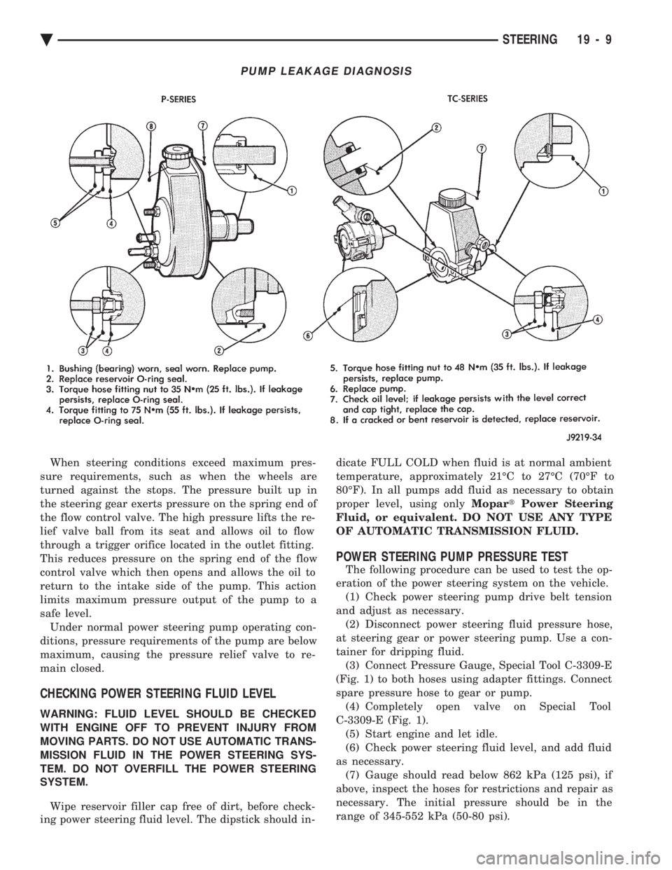
tainer for dripping fluid. (3) Connect Pressure Gauge, Special Tool C-3309-E
(Fig. 1) to both hoses using adapter fittings. Connect
spare pressure hose to gear or pump. (4) Completely open valve on Special Tool
C-3309-E (Fig. 1). (5) Start engine and let idle.
(6) Check power steering fluid level, and add fluid
as necessary. (7) Gauge should read below 862 kPa (125 psi), if
above, inspect the hoses for restrictions and repair as
necessary. The initial pressure should be in the
range of 345-552 kPa (50-80 psi).
PUMP LEAKAGE DIAGNOSIS
Ä STEERING 19 - 9
Page 1928 of 2438
CAUTION: The following test procedure involves test-
ing power steering pump maximum pressure output
and flow control valve operation. Do not leave valve
closed for more than 5 seconds as the pump could be
damaged.
(8) Close valve fully three times and record highest
pressure indicated each time. All three readings
must be above specifications and within 345 kPa
(50 psi) of each other. Power steering pump maximum relief pressure
is 8275 to 8975 kPa (1200 to 1300 psi.).
² Power steering pump pressures above specifications
but not within 345 kPa (50 psi) of each other, replace
pump.
² Pressures within 345 kPa (50 psi) of each other but
below specifications, replace pump.
CAUTION: Do not force the pump to operate against
the stops for more than 5 seconds at a time because,
pump damage will result.
(9) Open test valve. Turn steering wheel to the
extreme left and right positions until against the stops,
recording the highest indicated pressure at each posi-
tion. Compare pressure gauge readings to power steer-
ing pump specifications. If highest output pressures
are not the same against either stop, the steering gear
is leaking internally and must be replaced.
POWER STEERING PRESSURE SWITCH
New for 1993 M.Y., is the use of an idle quality power
steering pressure switch on some front wheel drive
passenger car applications. The purpose of this switch is to signal the power
train control module, that the power steering system is
putting additional load on the engine. This type of
condition exists when turning the front tires of the
vehicle, when the vehicle is stationary and the engine
is at idle speed. When this condition is sensed by the
power train control module, through a signal from the power steering pressure switch, engine idle
speed is increased. This increase in engine idle speed
compensates for the additional load, thus maintain-
ing the require engine idle speed and idle quality.
The power steering pressure switch is mounted to
the power steering pressure hose on the applications
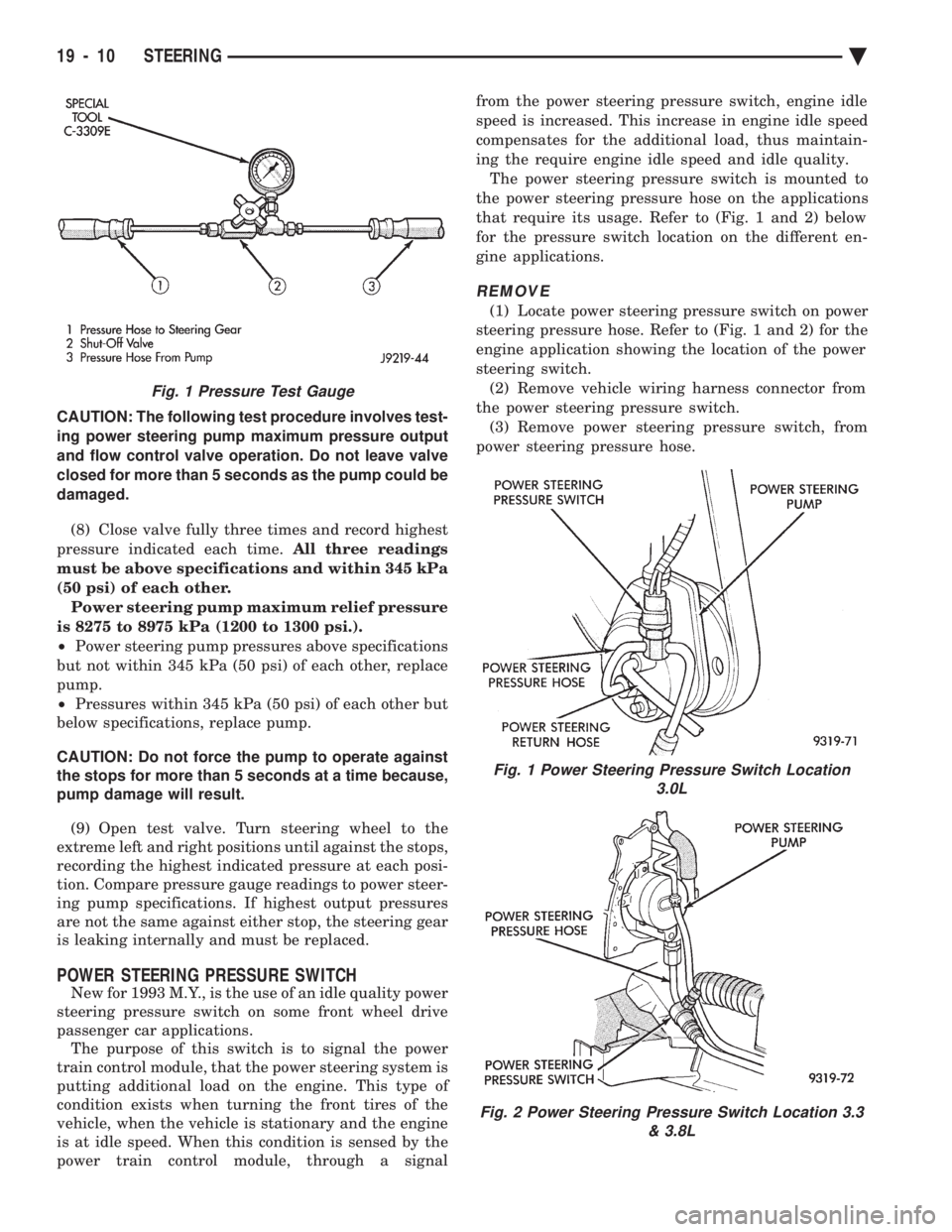
that require its usage. Refer to (Fig. 1 and 2) below
for the pressure switch location on the different en-
gine applications.
REMOVE
(1) Locate power steering pressure switch on power
steering pressure hose. Refer to (Fig. 1 and 2) for the
engine application showing the location of the power
steering switch. (2) Remove vehicle wiring harness connector from
the power steering pressure switch. (3) Remove power steering pressure switch, from
power steering pressure hose.
Fig. 1 Power Steering Pressure Switch Location 3.0L
Fig. 2 Power Steering Pressure Switch Location 3.3 & 3.8L
Fig. 1 Pressure Test Gauge
19 - 10 STEERING Ä