1993 CHEVROLET DYNASTY wheel
[x] Cancel search: wheelPage 745 of 2438
CHIME WARNING/REMINDER SYSTEM
CONTENTS
page page
BODY CONTROLLER REPLACEMENT ........ 5
CHIME MODULE REPLACEMENT AA and AP BODIES .............................. 5
CHIME SYSTEM DIAGNOSISÐAA AND AP BODIES .............................. 2
CHIME SYSTEM DIAGNOSISÐAC, AG, AJ AND AY BODIES ....................... 3
CHIME WARNING/REMINDER SYSTEM TEST . 1 GENERAL INFORMATION
.................. 1
HEADLAMP SWITCH REPLACEMENT ........ 5
KEY-IN SWITCH REPLACEMENT ............ 5
SEAT BELT BUCKLE REPLACEMENT ........ 5
SEAT BELT BUCKLE SWITCH TEST BUZZER SYSTEM .............................. 1
SERVICE PROCEDURES ................... 5
TIMED BUZZER-RELAY TESTÐAP BODY ..... 1
GENERAL INFORMATION
WARNING: ON VEHICLES EQUIPPED WITH AN AIR
BAG REFER TO THE AIR BAG PORTION OF THIS
SECTION FOR STEERING WHEEL OR SWITCH RE-
MOVAL AND INSTALLATION PROCEDURES.
BUZZER SYSTEM
The seat belt warning system uses both visual and
audible signals. A combined seat belt and key warn-
ing buzzer with a red light on the instrument panel. The system will always illuminate the seat belt
warning lamp for four to eight seconds when the ig-
nition switch is turned to the ON position. Also, only
if the driver does not fasten his seat belt, the buzzer
will sound during the same time interval. Passenger
belts are not connected to the system. A timed buzzer-relay is used to operate the system
for the time period. It consists of a time delay mech-
anism and buzzer assembly. Only the driver's seat
belt buckle has a switch that is connected to the sys-
tem.
CHIME WARNING/REMINDER SYSTEM
The chime warning/reminder system is similar in
operation to the buzzer system except for a more
pleasant sounding tone. This chime type tone sounds
for all three warning/reminder conditions; namely
headlamps left on, keys left in ignition and fasten
seat belt.
TIMED BUZZER-RELAY TESTÐAP BODY
PREPARATION
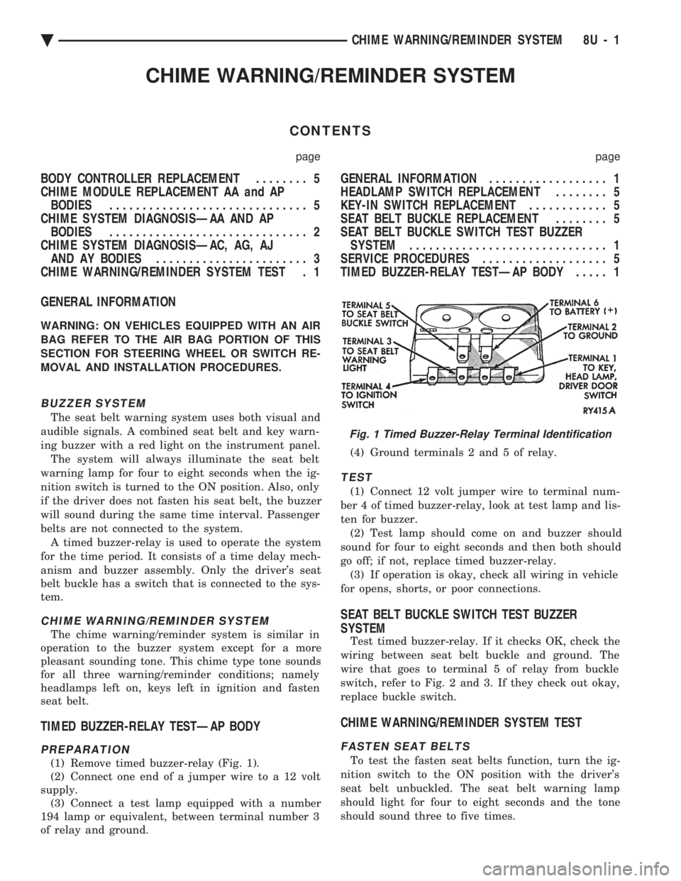
(1) Remove timed buzzer-relay (Fig. 1).
(2) Connect one end of a jumper wire to a 12 volt
supply. (3) Connect a test lamp equipped with a number
194 lamp or equivalent, between terminal number 3
of relay and ground. (4) Ground terminals 2 and 5 of relay.
TEST
(1) Connect 12 volt jumper wire to terminal num-
ber 4 of timed buzzer-relay, look at test lamp and lis-
ten for buzzer. (2) Test lamp should come on and buzzer should
sound for four to eight seconds and then both should
go off; if not, replace timed buzzer-relay. (3) If operation is okay, check all wiring in vehicle
for opens, shorts, or poor connections.
SEAT BELT BUCKLE SWITCH TEST BUZZER
SYSTEM
Test timed buzzer-relay. If it checks OK, check the
wiring between seat belt buckle and ground. The
wire that goes to terminal 5 of relay from buckle
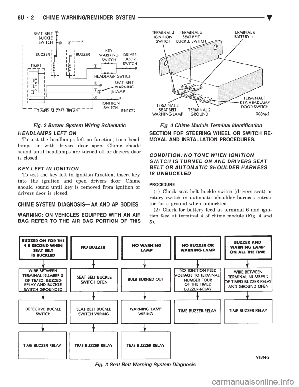
switch, refer to Fig. 2 and 3. If they check out okay,
replace buckle switch.
CHIME WARNING/REMINDER SYSTEM TEST
FASTEN SEAT BELTS
To test the fasten seat belts function, turn the ig-
nition switch to the ON position with the driver's
seat belt unbuckled. The seat belt warning lamp
should light for four to eight seconds and the tone
should sound three to five times.
Fig. 1 Timed Buzzer-Relay Terminal Identification
Ä CHIME WARNING/REMINDER SYSTEM 8U - 1
Page 746 of 2438
HEADLAMPS LEFT ON
To test the headlamps left on function, turn head-
lamps on with drivers door open. Chime should
sound until headlamps are turned off or drivers door
is closed.
KEY LEFT IN IGNITION
To test the key left in ignition function, insert key
into the ignition and open drivers door. Chime
should sound until key is removed from ignition or
drivers door is closed.
CHIME SYSTEM DIAGNOSISÐAA AND AP BODIES
WARNING: ON VEHICLES EQUIPPED WITH AN AIR
BAG REFER TO THE AIR BAG PORTION OF THIS SECTION FOR STEERING WHEEL OR SWITCH RE-
MOVAL AND INSTALLATION PROCEDURES.
CONDITION: NO TONE WHEN IGNITION
SWITCH IS TURNED ON AND DRIVERS SEATBELT OR AUTOMATIC SHOULDER HARNESSIS UNBUCKLED
PROCEDURE
(1) Check seat belt buckle switch (drivers seat) or
rotary switch in automatic shoulder harness retrac-
tor for a ground when unbuckled. (2) Check for battery feed at terminal 6 and igni-
tion feed at terminal 4 of chime module (Fig. 4 and
5).
Fig. 3 Seat Belt Warning System Diagnosis
Fig. 4 Chime Module Terminal IdentificationFig. 2 Buzzer System Wiring Schematic
8U - 2 CHIME WARNING/REMINDER SYSTEM Ä
Page 931 of 2438

WIRING DIAGRAMS AA-BODY
INDEX
Wiring Diagram
Name Sheet Number
Airbag System ...............................47
Clockspring ...............................47
Diagnostic Module ..........................47
Interface Grommet ..........................47
Sensor-Left ...............................47
Sensor-Right ..............................47
Squibb ..................................47
Air Conditioning Compressor ...................32, 33
Air Conditioning System (2.5L Engine) ...............71
A/C Cycling Switch ..........................71
Blower Motor ..............................71
Blower Switch .............................71
Control Switch .............................71
Damped Pressure Switch ......................71
Defrost Switch .............................71
Illumination Lamp ...........................71
Resistor .................................71
Air Conditioning System (3.0L Engine) ...............72
A/C Switch ...............................72
Blower Motor ..............................72
Blower Switch .............................72
Control Switch .............................72
Damped Pressure Switch ......................72
Defrost Switch .............................72
High Pressure Switch ........................72
Illumination Lamp ...........................72
Resistor .................................72
Anti-Lock Brake System .................41, 42, 43, 44
ABS Pump Motor Relay .......................41
ABS System Relay ..........................43
ABS Warning Lamp Relay ......................43
Brake Switch ..............................44
Controller ....................... .41, 42, 43, 44
Hydraulic Modulator .........................41
Ignition Switch .............................44
Park Brake Switch ...........................44
Wheel Sensors .............................42
Ash Receiver Lamp ...........................52
Automatic Shut-down Relay .................14, 20, 28
Automatic Transmission Park/Neutral Position and Back-Up Lamp Switch ...............................9
Back-Up Lamp Switch ..........................9
Battery ............................1,5,7,39,40
Blower Motor-A/C ............................71
Blower Motor-Heater ...........................71
Brake Switch ...............................44
Brake Warning Lamp Switch ......................11
Bulkhead Disconnect (50-Way) ................112, 113
Center High Mounted Stop Lamp ..........94, 98, 102, 105
Charging System (2.5L) ........................5,6
Battery ...................................5
Generator .................................6Wiring Diagram
Name Sheet Number
Heated Rear Window Switch .....................5
Charging System (3.0L) ........................7,8
Battery ....................................7
Generator .................................8
Ignition Off-Draw Connector .....................7
Cigar Lighter ................................45
Cigar Lighter Lamp ............................52
Circuit Breaker (30 Amp) Fuseblock Cavity #10 .......67, 82
Circuit Breaker (30 Amp) Fuseblock Cavity #13 . . .2, 66, 67, 86
Clockspring ............................. .47, 59
Cluster Printed Circuit Board .................119, 120
Cluster Printed Circuit Board Connectors .............118
Courtesy Lamps .............................76
Daytime Running Light Module ....................57
Deck Lid Ajar Switch ..........................78
Dimmer Switch-Headlamp .....................1,50
Distributor ......................... .15, 21, 22, 27
EGR Solenoid ...............................24
Electrically Heated Rear Window ...................84
Heated Rear Window .........................84
Switch ..................................84
Timer ...................................84
Electronically Tuned Stereo Radio without Name Brand Speakers ................................87
Electronically Tuned Stereo Radio with Name Brand Speakers ................................89
Speaker Choke .............................89
Speaker Relay .............................89
Electronic Cluster ........................... .121
Engine Coolant Sensor ................... .15, 21, 27
Engine Oil and Temperature Warning System (2.5L) .......39
Engine Oil and Temperature Warning System (3.0L) .......40
Engine Oil Pressure Switch/Sending Unit ...........39, 40
Engine Temperature Sending Unit ................39, 40
Engine Starter System (2.5L Engine & 3.0L ATX) .......9,10
Automatic Transmission Park/Neutral Position Switch .....9
Backup Lamp Switch ..........................9
EMCC Solenoid .............................9
Engine Starter Relay ..........................9
Manual Transmission Back-Up Lamp Switch ...........9
Permanent Magnet Engine Starter Motor .............9
Engine Temperature Sending Unit ................39, 40
Exhaust Gas Recirculation Diagnostic Solenoid ........13, 24
Fan Control System with A/C and Heater System (2.5L) ....32
A/C Compressor ............................32
A/C Compressor Clutch Relay ...................32
A/C High Pressure Switch ......................32
Fan Control Relay ...........................32
Radiator Fan Motor ..........................32
Fan Control System with A/C and Heater System (3.0L) ....33
A/C Conditioning Compressor ...................33
A/C Compressor Clutch Relay ...................33
Ä WIRING DIAGRAMS AA-BODY 8W - 181
Page 935 of 2438

Wiring Diagram
Name Sheet Number
Seat Belt Switch ............................46
Seat Belt Warning Chime ......................45
Seat Belt Warning Lamp .......................45
Sensors Airbag Sensor .............................47
Ambient Temperature Sensor ....................75
Engine Coolant Sensor .................. .15, 21, 27
Fuel Sensor ...............................17
Heated Oxygen Sensor .................. .12, 18, 24
Left Front Wheel Sensor .......................42
Left Rear Wheel Sensor .......................42
MAP Sensor ........................ .13, 19, 30
Output Speed Sensor .........................38
Right Front Wheel Sensor ......................42
Right Rear Wheel Sensor ......................42
Throttle Position (Sensor) .................12, 18, 24
Turbine Speed Sensor ........................38
Vehicle Speed Sensor .................. .15, 21, 28
Windshield Washer Low Fluid Sensor ..............63
Solenoids EMCC Solenoid .............................9
EVAP/Purge Solenoid ................... .13, 19, 23
Exhaust Gas Recirculation Diagnostic Solenoid ......13, 24
Transmission Solenoid ........................35
Speakers-Front Door and Rear w/o Name Brand Speakers . . .88 Left Front Door Speaker .......................88
Left Rear Door Speaker .......................88
Right Front Door Speaker ......................88
Right Rear Door Speaker ......................88
Speaker Choke ..............................89
Speakers-Front Door and Rear w/Name Brand Speakers ............................. .90, 91
Left Front Door Speakers ......................90
Left Rear Door Speaker .......................91
Right Front Door Speaker ......................90
Right Rear Door Speaker ......................91
Splices Splice A0 .....................1,2,4,6,8,39,40
Splice A1 .................................6
Splice A3 .......................... .48, 59, 67
Splice A4 ......................4,5,8,34,39,40
Splice A14 ..............................6,8
Splice A15 ..............................5,7
Splice A15-1 ...........................1,5,7
Splice A20 ............................6,8,43
Splice A21 ...............................??
Splice A21-1 ........................ .13, 19, 23
Splice A21-2 ...................... .13, 19, 23, 44
Splice A21-3 ..............................37
Splice A41 ...............................10
Splice A61 ...............................17
Splice A142 ......................6,8,14,20,24
Splice A142-1 .........................8,14,20
Splice A142-2 .............................26
Splice A142-4 .............................26
Splice B47 ...............................43
Splice B120 ...............................41Wiring Diagram
Name Sheet Number
Splice C7 .......................... .68, 71, 72
Splice D1 ................................34
Splice D2 ................................34
Splice E2-1 ............... .51, 68, 71, 72, 84, 87, 89
Splice E2-2 ............... .52, 68, 71, 72, 84, 87, 89
Splice E17 ...............................49
Splice F20 .................9,16,22,37,47,60,84
Splice F30 ...................... .45, 47, 48, 106
Splice F35 .......................... .66, 67, 85
Splice G5 ........................ .44, 45, 47, 77
Splice G7-1 ......................... .15, 21, 27
Splice G16 ...............................46
Splice G26 ........................... .45, 106
Splice K4 ................................24
Splice K4-1 ........................... .15, 21
Splice K4-2 ......................... .15, 21, 27
Splice K6 .......................... .13, 19, 25
Splice K7 .......................... .16, 22, 27
Splice K7-1 ...............................22
Splice K22 ...............................25
Splice K24 ...............................27
Splice L1 ...................... .93, 97, 101, 103
Splice L3 ................................55
Splice L7 ........................ .50, 56, 95, 99
Splice L7-1 ...............................56
Splice L7-2 ...............................55
Splice L7-3 ..................... .92, 97, 101, 103
Splice L20 ..............................1,49
Splice L39 ...............................55
Splice L43 ...............................56
Splice L60 ...............................55
Splice L61 ...............................56
Splice M1 ................................73
Splice M1-2 ................... .53, 74, 80, 87, 89
Splice M1-3 ........................ .39, 40, 53
Splice M1-4 ........................ .58, 76, 80
Splice M1-5 ........................... .58, 74
Splice M2-3 ........................... .54, 74
Splice M2-4 ........................... .58, 76
Splice M2-5 ........................... .58, 74
Splice P33 ...............................86
Splice P34 ...............................86
Splice Q1-1 ...............................82
Splice T13 ...............................38
Splice T16 ...............................35
Splice T41 ............................ .10, 37
Splice V6 ............................. .11, 64
Splice X13 ...............................90
Splice X15 ...............................90
Splice Z0 ..........................5,7,29,36
Splice Z1 ..............5,43,63,93,94,98, 102, 103
Splice Z1-1 ............... .32, 33, 49, 51, 56, 59, 84
Splice Z1-2 ................. .43, 52, 55, 68, 71, 72
Splice Z1-3 ........................... .41, 56
Splice Z1-4 .......46, 66, 69, 79, 82, 85, 92, 97, 101, 103
Splice Z1-5 ................. .46, 66, 69, 79, 82, 85
Splice Z1-7 ...............................98
Ä WIRING DIAGRAMS AA-BODY 8W - 185
Page 937 of 2438

Wiring Diagram
Name Sheet Number
Vehicle Speed Control Switch ...................59
Visor Vanity Mirror Lamp ........................73
Visual Message Center and Door Ajar Switches .......77, 78
Cluster Lamp ..............................77
Deck Lid Ajar Courtesy Lamp Switch ...............78
Headlamp Out Lamp .........................77
Left Front Door Ajar Lamp .....................77
Left Front Door Ajar Switch .....................78
Left Rear Door Ajar Lamp ......................77
Left Rear Door Ajar Switch .....................78Wiring Diagram
Name Sheet Number
Liftgate Ajar Lamp ..........................77
Low Washer Fluid Lamp .......................77
Right Front Door Ajar Lamp ....................77
Right Front Door Ajar Switch ....................78
Right Rear Door Ajar Lamp .....................77
Right Rear Door Ajar Switch ....................78
Stop Lamp Out Lamp ........................77
Tail Lamp Out Lamp .........................77
Visual Message Center Connector ..................117
Wheel Sensors ..............................42
Ä WIRING DIAGRAMS AA-BODY 8W - 187
Page 1001 of 2438
1993 Front Wheel Drive Car
Publication No. 81-270-3103
TSB 08-69-94 December 9, 1994
Page 1063 of 2438
WIRING DIAGRAMS AC-AY BODY INDEX
Wiring Diagram
Name Sheet Number
ABS Data Link Connector ........................49
Airbag System ........................... .57, 58
Clockspring ...............................57
Diagnostic Module ..........................57
Interface Grommet ..........................58
Sensor-Left ...............................58
Sensor-Right ..............................58
Squib (Airbag Igniter) ........................57
Air Conditioning and Heater System (2.5L) .............53
A/C Switch ...............................53
Blower Motor ..............................53
Compressor ...............................53
Defrost Switch .............................53
Diode ...................................53
Illumination Lamps ..........................53
Low Pressure Switch .........................53
Resistor .................................53
Switch-Blower .............................53
Air Conditioning Variable Output Compressor ..........113
Air Exhaust Solenoid-Automatic Air Load Leveling ........40
Air Suspension System .................41, 42, 43, 44
Air Exhaust Solenoid .........................42
Air Suspension Relay .........................42
Air Suspension System Control Module .......41, 43, 176
Compressor Assembly ........................42
Compressor Motor ..........................42
Height Sensors ............................44
Shock Absorber ............................43
Solenoids ............................ .41, 44
Air Suspension System Control Module .........41, 43, 176
Antennas ............................. .118, 126
Anti-Lock Brake System ............45, 46, 47, 48, 49, 50
ABS System Relay ..........................47
Controller .................. .45, 46, 47, 48, 49, 50
Data Link Connector .........................49
Left Front Wheel Sensor .......................50
Left Rear Wheel Sensor .......................50
Modulator ............................ .45, 48
Pump Motor ..............................46
Pump and Motor Relay .......................46
Right Front Wheel Sensor ......................50
Right Rear Wheel Sensor ......................50
Yellow Lamp Relay ..........................49
Anti-Lock Brake System Controller .....45, 46, 47, 48, 49, 50
Anti-Lock Brake System Modulator Connectors .........172
Anti-Lock Brake System Controller Connector ..........175
Anti-Lock Brake System Modulator ...............45, 48
ATC In-line Connector ........................ .117
Automatic Air Load Leveling System ..............39, 40
Air Exhaust Solenoid .........................40
Compressor Assembly ........................40
Compressor Motor ..........................40Wiring Diagram
Name Sheet Number
Load Leveling Relay .........................40
Shock Absorber ............................40
Automatic Day/Night Mirror .................... .124
Automatic Temperature Control .............115, 116, 117
A/C Blower Motor ......................... .115
Ambient Sensor .......................... .117
ATC Control Switch ........................ .116
ATC In Line Connector ...................... .117
ATC Power Module ........................ .115
In Car Senso r............................ .115
In Car Sensor Motor ....................... .115
Sun Sensor ............................. .115
Water Sensor ............................ .117
Automatic Temperature Control (Radiator and
Compressor 3.3L & 3.8L) .................. .113, 114
A/C Ambient Temperature Switch ................114
A/C Compressor Clutch Relay ...................113
A/C Fan Cutout Switch ...................... .114
A/C High Pressure Cutout Switch ................114
A/C Low Pressure Switch .................... .114
A/C Variable Output Compressor .................113
Diode ................................. .113
Radiator Fan Motor ........................ .113
Radiator Fan Relay ........................ .114
Automatic Shutdown Relay .......................29
Automatic Temperature Control In-line Connector ........206
Automatic Temperature Control Module Connector .......200
Back-Up Lamp Relay ..........................33
Battery ...............................2,5,7,9
Body Computer 2 (Electronic Cluster) .........101, 102, 194
25-Pin Connector ...................... .101, 102
Body Computer 1 (Electronic Cluster) .........103, 104, 195
25-Pin Connector ...................... .103, 104
Data Link Connector ....................... .103
Halo Lamp .............................. .104
Relay ................................. .103
Body Computer (Mechanical Cluster w/Visual Message Ctr) ......................... .196, 197
Body Computer (Mechanical Cluster w/o Visual Message Ctr) ......................... .198, 199
Body Computer 1 (Mechanical Cluster w/o Visual Message Ctr) ..................... .108, 109, 110
25-Pin Connector ................... .108, 109, 110
Data Link Connector ....................... .110
Halo Lamp .............................. .108
Key-In Switch ............................ .109
Relay Bank ............................. .108
Body Computer 2 (Mechanical Cluster with Visual Message Ctr) ..................... .105, 106, 107
25-Pin Connector ................... .105, 106, 107
Data Link Connector ....................... .106
Halo Lamp .............................. .106
Key-In Switch ............................ .107
Ä WIRING DIAGRAMS AC-AY BODY 8W - 313
Page 1069 of 2438
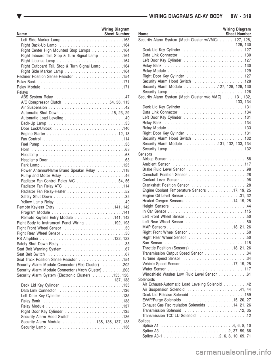
Wiring Diagram
Name Sheet Number
Left Side Marker Lamp ...................... .163
Right Back-Up Lamp ....................... .164
Right Center High Mounted Stop Lamps ............164
Right Inboard Tail, Stop & Turn Signal Lamp .........164
Right License Lamp ........................ .164
Right Outboard Tail, Stop & Turn Signal Lamp ........164
Right Side Marker Lamp ..................... .164
Recliner Position Sense Resistor ..................154
Relay Bank ............................... .171
Relay Module ............................. .171
Relays ABS System Relay ..........................47
A/C Compressor Clutch .................54, 56, 113
Air Suspension .............................42
Automatic Shut Down .................. .15, 23, 29
Automatic Load Leveling .......................40
Back-Up Lamp .............................33
Door Lock/Unlock ......................... .140
Engine Starter .......................... .12, 13
Fan Control ............................. .114
Fuel Pump ...............................36
Horn ...................................63
Headlamp ................................68
Headlamp Door ............................68
Park Lamp .............................. .125
Power Antenna/Name Brand Speaker Relay ..........118
Pump and Motor Relay .......................46
Radiator Fan Control Relay A/C ................54, 56
Radiator Fan Relay ATC ..................... .114
Radiator Fan Relay-Heater ......................52
Safety Shut Down ...........................35
Yellow Lamp Relay ..........................49
Remote Keyless Entry ..................... .141, 142
Program Module .......................... .141
Remote Keyless Entry Module ...............141, 142
Right Body to Instrument Panel Wiring ...........192, 193
Right Front Wheel Sensor .......................50
Right Rear Wheel Sensor ........................50
RS Amplifier ........................... .122, 123
Safety Shut Down Relay ........................35
Seat Belt Warning System .......................67
Seat Belt Switch .............................67
Seat Track Position Sense Resistor .................154
Security Alarm Module Connector (Elec Cluster) ........202
Security Alarm Module Connector (Mech Cluster) ........203
Security Alarm System (Electronic Cluster) ........135, 136,
137, 138
Deck Lid Key Cylinder ...................... .135
Data Link Connector ....................... .136
Left Door Key Cylinder ...................... .135
Relay Bank ............................. .138
Relay Module ............................ .137
Right Door Key Cylinder ..................... .135
Security Alarm Hood Switch ...................136
Security Alarm Module .............135, 136, 137, 138
Security Lamp ........................... .136Wiring Diagram
Name Sheet Number
Security Alarm System (Mech Cluster w/VMC) ......127, 128,
129, 130
Deck Lid Key Cylinder ...................... .127
Data Link Connector ....................... .130
Left Door Key Cylinder ...................... .127
Relay Bank ............................. .130
Relay Module ............................ .129
Right Door Key Cylinder ..................... .127
Security Alarm Hood Switch ...................128
Security Alarm Module .............127, 128, 129, 130
Security Lamp ........................... .128
Security Alarm System (Mech Cluster w/o VMC) . . . .131, 132,
133, 134
Deck Lid Key Cylinder ...................... .131
Data Link Connector ....................... .134
Left Door Key Cylinder ...................... .131
Relay Bank ............................. .134
Relay Module ............................ .133
Right Door Key Cylinder ..................... .131
Security Alarm Hood Switch ...................132
Security Alarm Module .............131, 132, 133, 134
Security Lamp ........................... .132
Sensors Airbag Sensor .............................58
Ambient Sensor .......................... .117
Brake Fluid Level Sensor ......................98
Camshaft Position Sensor ......................28
Coolant Level Sensor .........................98
Crankshaft Position Sensor .....................28
Engine Coolant Temperature Sensors ..........17, 19, 25
Engine Oil Level Sensor .................... .31, 32
Heated Oxygen Sensors ................. .14, 19, 25
Height Sensors ............................44
In Car Senso r............................ .115
Left Front Wheel Sensor .......................50
Left Rear Wheel Sensor .......................50
MAP Sensors ........................ .18, 21, 26
Right Front Wheel Sensor ......................50
Right Rear Wheel Sensor ......................50
Sun Sensor ............................. .115
Throttle Position (Sensors) ................18, 21, 26
Transmission Output Speed Sensor ................34
Turbine Speed Sensor ........................34
Vehicle Speed Sensor .................. .17, 19, 25
Water Sensor ............................ .117
Windshield Washer Low Fluid Level Sensor ...........61
Solenoids Air Exhaust-Automatic Load Leveling Solenoid .........42
Air Suspension Solenoid ................... .41, 44
Deck Lid Release Solenoid ................... .159
EVAP/Purge Solenoids .................. .15, 20, 27
Exhaust Gas Recirculation Solenoids ..........14, 21, 26
Transmission Solenoid .................... .12, 35
Transmission TCC LU Solenoid ..................12
Splices Splice A1 ...........................4,6,8,10
Splice A3 .........................2,37,59,66
Splice A3-1 .....................2,6,8,10,69,71
Ä WIRING DIAGRAMS AC-AY BODY 8W - 319