1993 CHEVROLET DYNASTY wheel
[x] Cancel search: wheelPage 552 of 2438
CLUSTER BEZEL REPLACEMENT
(1) Remove four screws holding bezel to instru-
ment panel (Fig. 7). (2) Remove bezel over steering wheel. (3) For installation reverse above procedures.
CLUSTER MASK AND LENS
REMOVAL
(1) Remove instrument cluster bezel.
(2) Remove five screws holding mask and lens to
cluster. (3) Remove mask and lens.
(4) For installation reverse above procedures.
CLUSTER ASSEMBLY REPLACEMENT
(1) Disconnect battery to assure no Air Bag Sys-
tem fault codes are stored. (2) Remove cluster bezel (Fig. 7).
(3) Remove the upper steering column cover.
(4) Remove the four screws attaching cluster hous-
ing to the base panel. (5) Pull cluster rearward, reach behind cluster and
disconnect the two wiring harnesses. (6) Remove cluster assembly.
INSTALLATION (1) Connect wiring harnesses.
(2) Position cluster and secure to base panel with
four screws. (3) Install upper and lower steering column cover.
(4) Install cluster bezel.
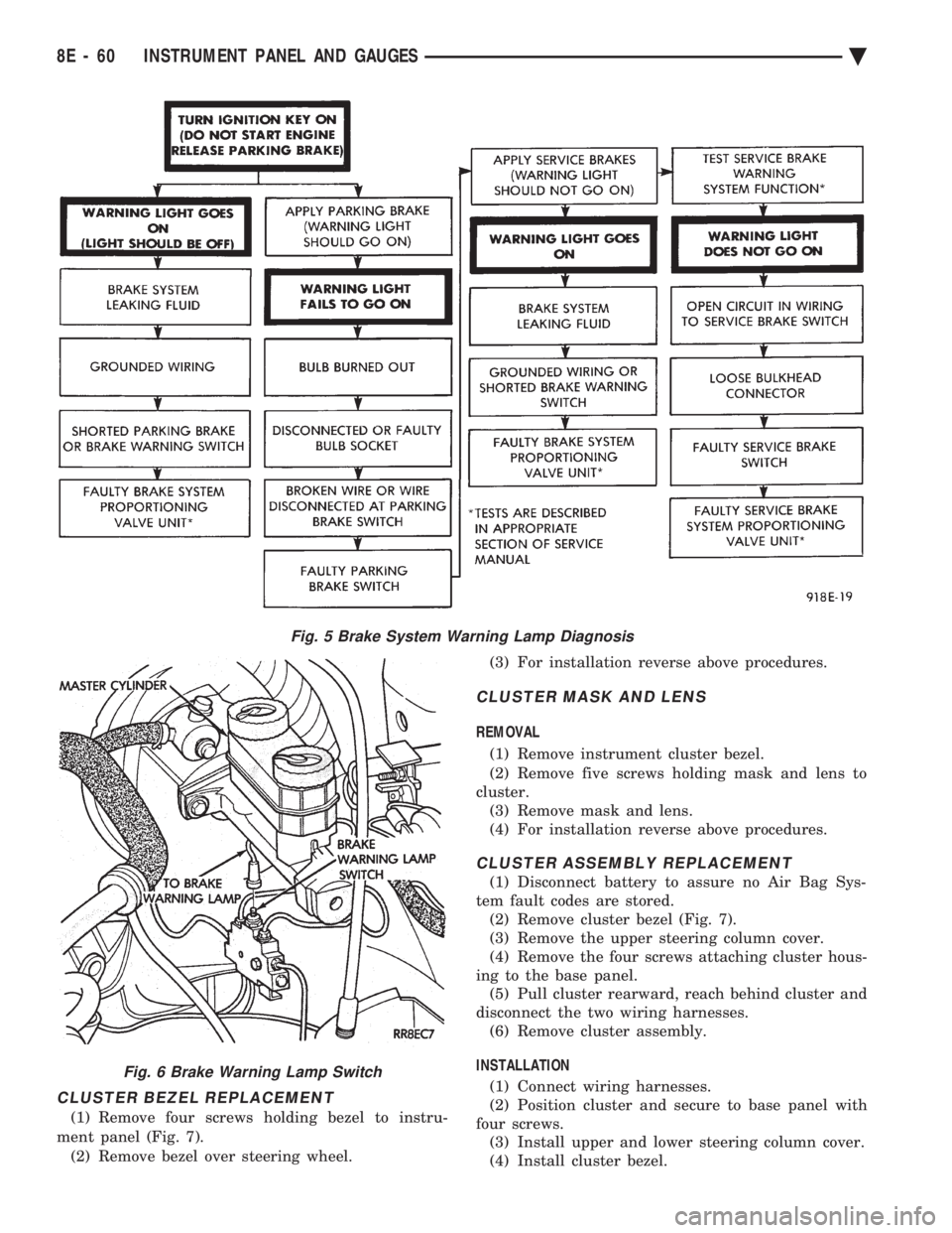
Fig. 5 Brake System Warning Lamp Diagnosis
Fig. 6 Brake Warning Lamp Switch
8E - 60 INSTRUMENT PANEL AND GAUGES Ä
Page 589 of 2438
(8) Upon establishing that the fault is in the an-
tenna assembly, it may be traced to one or more of
the following conditions: (a) Broken lead-in wire or shielding.
(b) Grounded lead-in wire or mast assembly.
(c) Moisture in support tube or lead-in assembly.
(d) Poor connection at antenna lead-in assembly
or shielding ground.
REMOVAL
(1) Disconnect battery negative cable.
(2) Remove the right front fender splash shield fas-
teners and pull shield away from the wheel housing.
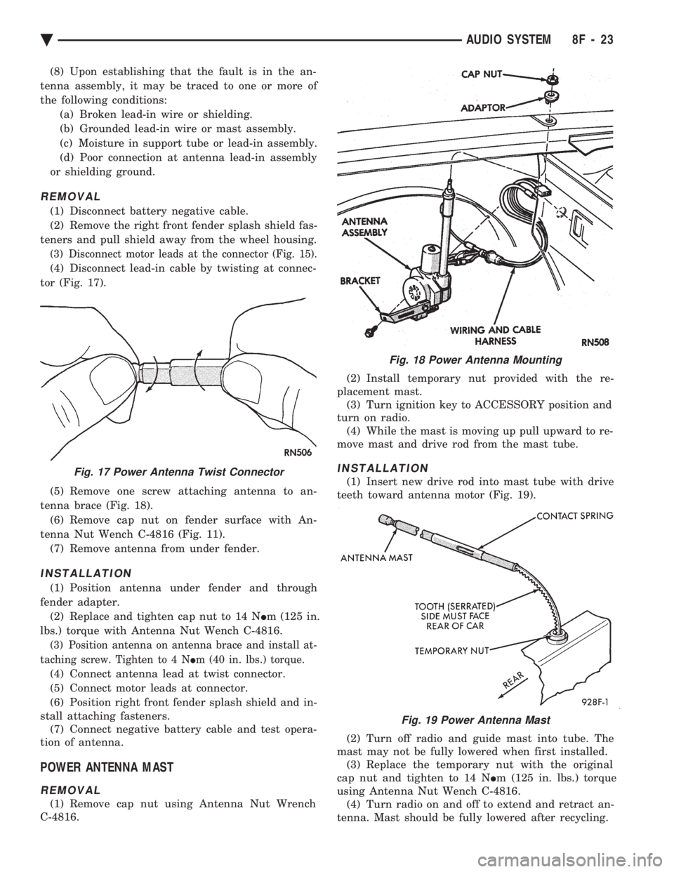
(3) Disconnect motor leads at the connector (Fig. 15).
(4) Disconnect lead-in cable by twisting at connec-
tor (Fig. 17).
(5) Remove one screw attaching antenna to an-
tenna brace (Fig. 18). (6) Remove cap nut on fender surface with An-
tenna Nut Wench C-4816 (Fig. 11). (7) Remove antenna from under fender.
INSTALLATION
(1) Position antenna under fender and through
fender adapter. (2) Replace and tighten cap nut to 14 N Im (125 in.
lbs.) torque with Antenna Nut Wench C-4816.
(3) Position antenna on antenna brace and install at-
taching screw. Tighten to 4 N Im (40 in. lbs.) torque.
(4) Connect antenna lead at twist connector.
(5) Connect motor leads at connector.
(6) Position right front fender splash shield and in-
stall attaching fasteners. (7) Connect negative battery cable and test opera-
tion of antenna.
POWER ANTENNA MAST
REMOVAL
(1) Remove cap nut using Antenna Nut Wrench
C-4816. (2) Install temporary nut provided with the re-
placement mast. (3) Turn ignition key to ACCESSORY position and
turn on radio. (4) While the mast is moving up pull upward to re-
move mast and drive rod from the mast tube.
INSTALLATION
(1) Insert new drive rod into mast tube with drive
teeth toward antenna motor (Fig. 19).
(2) Turn off radio and guide mast into tube. The
mast may not be fully lowered when first installed. (3) Replace the temporary nut with the original
cap nut and tighten to 14 N Im (125 in. lbs.) torque
using Antenna Nut Wench C-4816. (4) Turn radio on and off to extend and retract an-
tenna. Mast should be fully lowered after recycling.
Fig. 18 Power Antenna Mounting
Fig. 17 Power Antenna Twist Connector
Fig. 19 Power Antenna Mast
Ä AUDIO SYSTEM 8F - 23
Page 594 of 2438
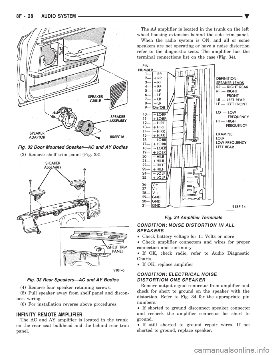
(3) Remove shelf trim panel (Fig. 33).
(4) Remove four speaker retaining screws.
(5) Pull speaker away from shelf panel and discon-
nect wiring. (6) For installation reverse above procedures.
INFINITY REMOTE AMPLIFIER
The AC and AY amplifier is located in the trunk
on the rear seat bulkhead and the behind rear trim
panel. The AJ amplifier is located in the trunk on the left
wheel housing extension behind the side trim panel. When the radio system is ON, and all or some
speakers are not operating or have a noise distortion
refer to the diagnostic tests. The amplifier has the
terminal connections list on the case (Fig. 34).
CONDITION: NOISE DISTORTION IN ALL SPEAKERS
² Check battery voltage for 11 Volts or more
² Check amplifier connectors and wires for proper
connection and continuity
² If OK, check radio, refer to Audio Diagnostic
Charts.
² If OK, replace amplifier
CONDITION: ELECTRICAL NOISE
DISTORTION ONE SPEAKER
Remove output signal connector from amplifier and
check for short to ground on the speaker with the
distortion. Refer to Fig. 34 for the appropriate pin
numbers.
² If shorted to ground disconnect speaker connector
and recheck the amplifier connector for short to
ground.
² If still shorted to ground repair wires. If not
shorted to ground, replace speaker.
Fig. 32 Door Mounted SpeakerÐAC and AY Bodies
Fig. 33 Rear SpeakersÐAC and AY Bodies
Fig. 34 Amplifier Terminals
8F - 28 AUDIO SYSTEM Ä
Page 597 of 2438
HORNS
CONTENTS
page page
GENERAL INFORMATION .................. 1
HORN SWITCH REPLACEMENT ............ 3 TESTING HORN SYSTEM
................. 1
GENERAL INFORMATION
WARNING: ON VEHICLES EQUIPPED WITH AIR
BAG, SEE GROUP 8M, RESTRAINT SYSTEMS FOR
STEERING WHEEL OR COLUMN REMOVAL PROCE-
DURES.
The horn circuit consists of a horn switch, horn re-
lay, and horns. The horn circuit feed is from the fuse
box to the number 1 terminal on the horn relay.
When the horn switch is depressed, this completes
the circuit to ground. This activates the horn relay
and an set of contacts in the relay to close, which al-
lows current to flow to the horn(s). The horn ground
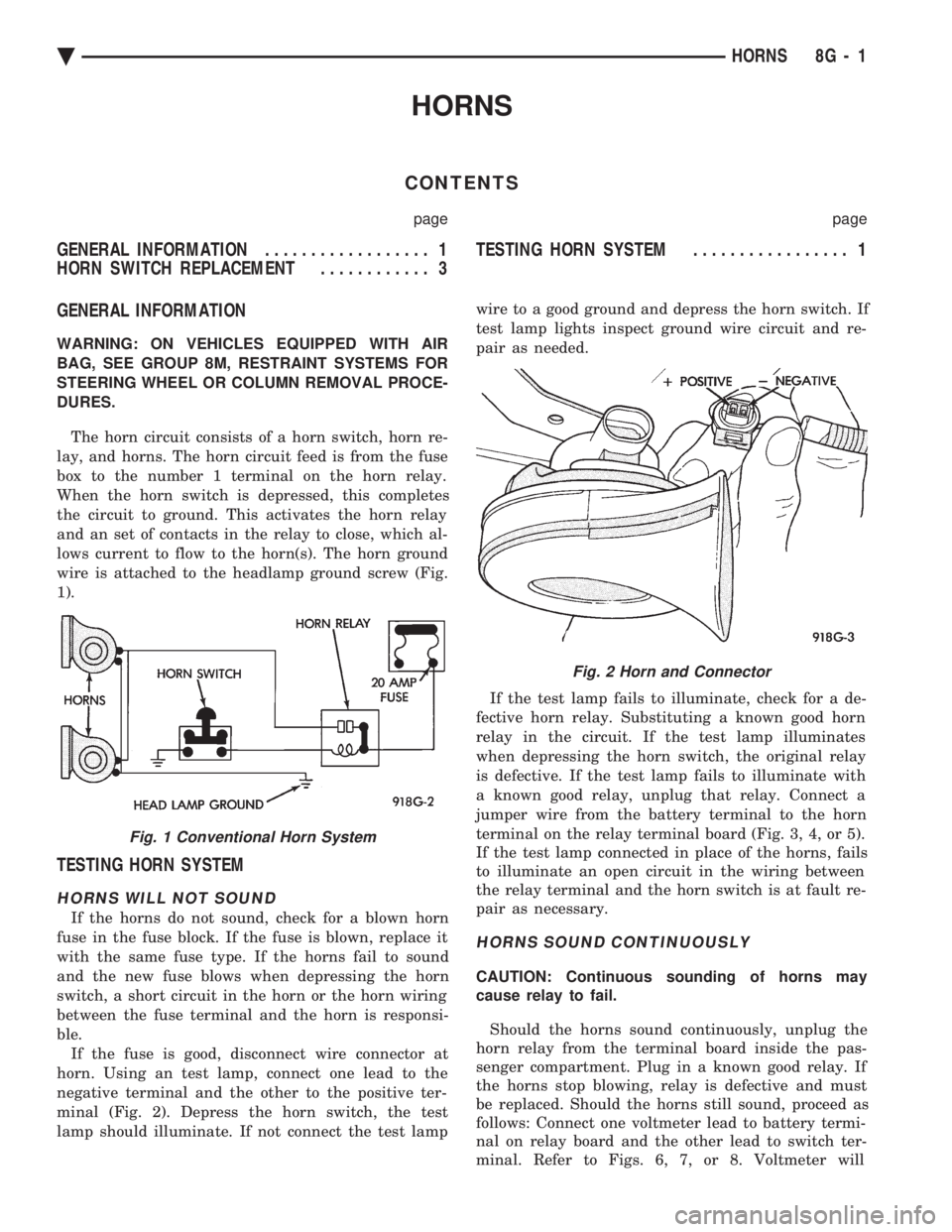
wire is attached to the headlamp ground screw (Fig.
1).
TESTING HORN SYSTEM
HORNS WILL NOT SOUND
If the horns do not sound, check for a blown horn
fuse in the fuse block. If the fuse is blown, replace it
with the same fuse type. If the horns fail to sound
and the new fuse blows when depressing the horn
switch, a short circuit in the horn or the horn wiring
between the fuse terminal and the horn is responsi-
ble. If the fuse is good, disconnect wire connector at
horn. Using an test lamp, connect one lead to the
negative terminal and the other to the positive ter-
minal (Fig. 2). Depress the horn switch, the test
lamp should illuminate. If not connect the test lamp wire to a good ground and depress the horn switch. If
test lamp lights inspect ground wire circuit and re-
pair as needed.
If the test lamp fails to illuminate, check for a de-
fective horn relay. Substituting a known good horn
relay in the circuit. If the test lamp illuminates
when depressing the horn switch, the original relay
is defective. If the test lamp fails to illuminate with
a known good relay, unplug that relay. Connect a
jumper wire from the battery terminal to the horn
terminal on the relay terminal board (Fig. 3, 4, or 5).
If the test lamp connected in place of the horns, fails
to illuminate an open circuit in the wiring between
the relay terminal and the horn switch is at fault re-
pair as necessary.
HORNS SOUND CONTINUOUSLY
CAUTION: Continuous sounding of horns may
cause relay to fail.
Should the horns sound continuously, unplug the
horn relay from the terminal board inside the pas-
senger compartment. Plug in a known good relay. If
the horns stop blowing, relay is defective and must
be replaced. Should the horns still sound, proceed as
follows: Connect one voltmeter lead to battery termi-
nal on relay board and the other lead to switch ter-
minal. Refer to Figs. 6, 7, or 8. Voltmeter will
Fig. 1 Conventional Horn System
Fig. 2 Horn and Connector
Ä HORNS 8G - 1
Page 599 of 2438
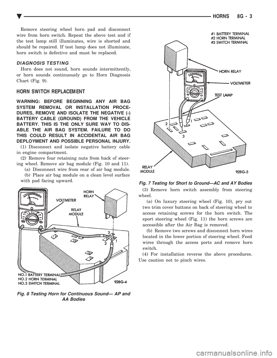
Remove steering wheel horn pad and disconnect
wire from horn switch. Repeat the above test and if
the test lamp still illuminates, wire is shorted and
should be repaired. If test lamp does not illuminate,
horn switch is defective and must be replaced.
DIAGNOSIS TESTING
Horn does not sound, horn sounds intermittently,
or horn sounds continuously go to Horn Diagnosis
Chart (Fig. 9).
HORN SWITCH REPLACEMENT
WARNING: BEFORE BEGINNING ANY AIR BAG
SYSTEM REMOVAL OR INSTALLATION PROCE-
DURES, REMOVE AND ISOLATE THE NEGATIVE (-)
BATTERY CABLE (GROUND) FROM THE VEHICLE
BATTERY. THIS IS THE ONLY SURE WAY TO DIS-
ABLE THE AIR BAG SYSTEM. FAILURE TO DO
THIS COULD RESULT IN ACCIDENTAL AIR BAG
DEPLOYMENT AND POSSIBLE PERSONAL INJURY. (1) Disconnect and isolate negative battery cable
in engine compartment. (2) Remove four retaining nuts from back of steer-
ing wheel. Remove air bag module (Fig. 10 and 11). (a) Disconnect wire from rear of air bag module.
(b) Place air bag module on a clean level surface
with pad facing upward.
(3) Remove horn switch assembly from steering
wheel. (a) On luxury steering wheel (Fig. 10), pry out
two trim cover buttons on back of steering wheel to
access retaining screws for the horn switch. The
sport steering wheel (Fig. 11) the horn screws are
accessible after the Air Bag is removed. (b) Remove two screws and disconnect horn wires
located in the lower portion of steering wheel. Feed
wires through the access ports and remove horn
switch.
(4) For installation reverse the above procedures.
Use caution not to pinch wires.
Fig. 8 Testing Horn for Continuous SoundÐ AP and AA Bodies
Fig. 7 Testing for Short to GroundÐAC and AY Bodies
Ä HORNS 8G - 3
Page 601 of 2438
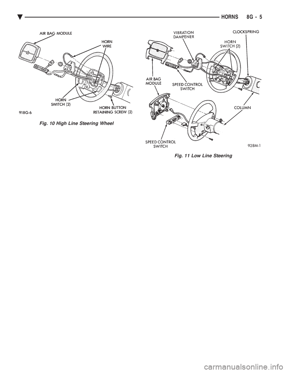
Fig. 10 High Line Steering Wheel
Fig. 11 Low Line Steering
Ä HORNS 8G - 5
Page 603 of 2438
VEHICLE SPEED CONTROL
CONTENTS
page page
CHECKING FOR FAULT CODE .............. 3
DIAGNOSIS PROCEDURES ................ 2
GENERAL INFORMATION .................. 1
INOPERATIVE SYSTEM ................... 3
POWERTRAIN CONTROL MODULE ELECTRICAL TEST ................................ 5
ROAD TEST ............................ 2
SERVO ELECTRICAL TESTS ............... 4
SERVO UNIT ............................ 9 SERVO VACUUM TEST
................... 9
STOP LAMP VEHICLE SPEED CONTROL SWITCH TEST ......................... 8
VACUUM SUPPLY TEST .................. 9
VEHICLE SPEED CONTROL SWITCH REMOVAL ........................... 10
VEHICLE SPEED CONTROL SWITCH TEST . . . 8
VEHICLE SPEED CONTROL ELECTRICAL TESTS ............................... 3
GENERAL INFORMATION
The vehicle speed control is electronically con-
trolled and vacuum operated. The electronic control
is integrated into the powertrain control module, lo-
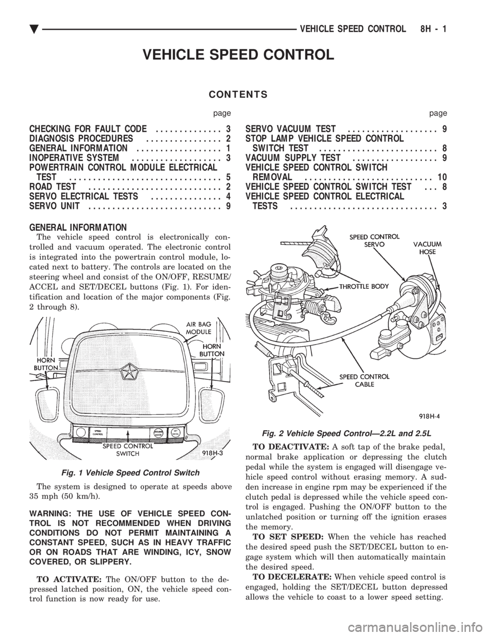
cated next to battery. The controls are located on the
steering wheel and consist of the ON/OFF, RESUME/
ACCEL and SET/DECEL buttons (Fig. 1). For iden-
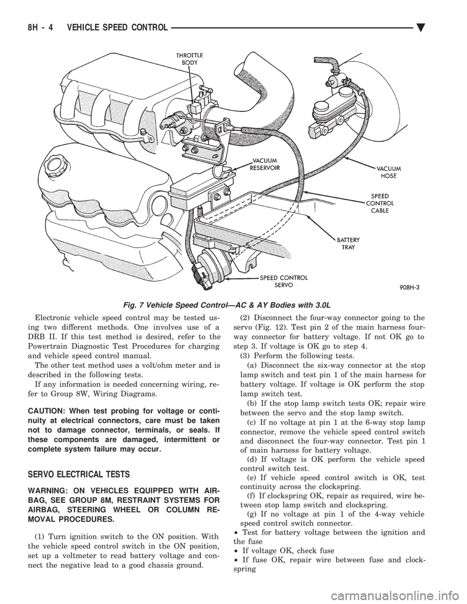
tification and location of the major components (Fig.
2 through 8).
The system is designed to operate at speeds above
35 mph (50 km/h).
WARNING: THE USE OF VEHICLE SPEED CON-
TROL IS NOT RECOMMENDED WHEN DRIVING
CONDITIONS DO NOT PERMIT MAINTAINING A
CONSTANT SPEED, SUCH AS IN HEAVY TRAFFIC
OR ON ROADS THAT ARE WINDING, ICY, SNOW
COVERED, OR SLIPPERY.
TO ACTIVATE: The ON/OFF button to the de-
pressed latched position, ON, the vehicle speed con-
trol function is now ready for use. TO DEACTIVATE:
A soft tap of the brake pedal,
normal brake application or depressing the clutch
pedal while the system is engaged will disengage ve-
hicle speed control without erasing memory. A sud-
den increase in engine rpm may be experienced if the
clutch pedal is depressed while the vehicle speed con-
trol is engaged. Pushing the ON/OFF button to the
unlatched position or turning off the ignition erases
the memory. TO SET SPEED: When the vehicle has reached
the desired speed push the SET/DECEL button to en-
gage system which will then automatically maintain
the desired speed. TO DECELERATE: When vehicle speed control is
engaged, holding the SET/DECEL button depressed
allows the vehicle to coast to a lower speed setting.
Fig. 1 Vehicle Speed Control Switch
Fig. 2 Vehicle Speed ControlÐ2.2L and 2.5L
Ä VEHICLE SPEED CONTROL 8H - 1
Page 606 of 2438
Electronic vehicle speed control may be tested us-
ing two different methods. One involves use of a
DRB II. If this test method is desired, refer to the
Powertrain Diagnostic Test Procedures for charging
and vehicle speed control manual. The other test method uses a volt/ohm meter and is
described in the following tests. If any information is needed concerning wiring, re-
fer to Group 8W, Wiring Diagrams.
CAUTION: When test probing for voltage or conti-
nuity at electrical connectors, care must be taken
not to damage connector, terminals, or seals. If
these components are damaged, intermittent or
complete system failure may occur.
SERVO ELECTRICAL TESTS
WARNING: ON VEHICLES EQUIPPED WITH AIR-
BAG, SEE GROUP 8M, RESTRAINT SYSTEMS FOR
AIRBAG, STEERING WHEEL OR COLUMN RE-
MOVAL PROCEDURES.
(1) Turn ignition switch to the ON position. With
the vehicle speed control switch in the ON position,
set up a voltmeter to read battery voltage and con-
nect the negative lead to a good chassis ground. (2) Disconnect the four-way connector going to the
servo (Fig. 12). Test pin 2 of the main harness four-
way connector for battery voltage. If not OK go to
step 3. If voltage is OK go to step 4. (3) Perform the following tests.(a) Disconnect the six-way connector at the stop
lamp switch and test pin 1 of the main harness for
battery voltage. If voltage is OK perform the stop
lamp switch test. (b) If the stop lamp switch tests OK; repair wire
between the servo and the stop lamp switch. (c) If no voltage at pin 1 at the 6-way stop lamp
connector, remove the vehicle speed control switch
and disconnect the four-way connector. Test pin 1
of main harness for battery voltage. (d) If voltage is OK perform the vehicle speed
control switch test. (e) If vehicle speed control switch is OK, test
continuity across the clockspring. (f) If clockspring OK, repair as required, wire be-
tween stop lamp switch and clockspring. (g) If no voltage at pin 1 of the 4-way vehicle
speed control switch connector.
² Test for battery voltage between the ignition and
the fuse
² If voltage OK, check fuse
² If fuse OK, repair wire between fuse and clock-
spring
Fig. 7 Vehicle Speed ControlÐAC & AY Bodies with 3.0L
8H - 4 VEHICLE SPEED CONTROL Ä