Page 73 of 279

F3 FUEL SYSTEM
t 3EoF3-344
1
FUEL SYSTEM
FUEL PUMP
inspection
Fuel pump operation
1. Connect the diagnosis connector F/P and GND terminals
by using a jumper wire.
2. Remove the fuel filler cap.
3. Turn ON the ignition switch.
4.
Listen at the filler inlet for the operational sou.nd of the fuel
pump.
5. Install the fuel filler cap.
6. If no sound is heard, measure the voltage between the fuel
pump connector (G/R) to a ground.
Voltage: 8attey vo kage
7. If not as specified, check the circuit opening relay and circuit.
8. ff as specified, check fur continuity between fuel pump con-
nector (G/R) and (B).
9. If there is continuity, reptace the fuel pump.
10. If there is no continuity, repair the ground circuit.
f3EOF3.345
13EOF3-346 FUEL PUMP RESlSTORlRELAY
System Operation
1. Remove the rear seat cushion.
2. Measure the voltage at the fuel pump connector terminal
A (G/R).
Voltage
I
Cranking
1 Battery voltage
Ignition switch ON ov 3. If not as specified, perform the following inspections, and
repair or replace as necessary.
l Fuel pump resistor/relay resistance
(Refer to page F3-41.)
l ECU 11 terminal voltage (Refer to page F3-45.)
l Wiring harness and connector
F3-40
ii e -
*
_~ --
C --
A-'
-,
-,
--
--
-1
E
7
2
I
i 3EAR SE
--
Page 74 of 279

FUEL SYSTEM F3
13EOF3.34
c I 13EOF3-364 FUEL PUMP CONNECTOR
/
!NSTALL CLAMPS
I
l nspection
1, Disconnect the resistor/relay connector.
2. Ground the fuel pump resistor relay terminal D.
3. Apply battery voltage and check for continuity as shown.
Terminal C
Continuity between A and I3
Battery voltage applied NO
ov Yes
4. Measure the resistance between terminals E and F.
Resistance : 0.38--0.42Q (at 2O*C {6S°F 1)
PRESSURE REGULATOR
Inspection
Fuel line pressure
Warning
l Before performing the following operation, release
the fuel pressure from the fuel system to reduce the
possibility of injury or fire. (Refer to page F3-21.)
1. Disconnect the negative battery terminal.
2. Connect a fuel pressure gauge between the fuel filter and
the fuel main hose. (install clamps as shown.) , .
I
3. Connect the negative battery terminal.
/t.
4, Start the engine and run it at idle.
5. Measure the fuel line pressure.
Fuel line pressure:
206-255 kPa [ 2.1-2.6 kgflcml, 30-37 psi )
6. Disconnect the upper vacuum hose from the pressure regu-
lator and measure the fuel line pressure.
Fuel line pressure:
304-392 kPa (3.1-4.0 kgf/cm2, 44-57 psi )
F3-41
Page 75 of 279

F3 FUEL SYSTEM
13EOt=3-349
f3EOF3-350
0
0
ECU
G
0
0 i
13EOF3-35
tNJECTOR
t nspection
injector resistance
1. Disconnect the injector harness,
2. Measure resistance of the injector.
Resistance: l-3Q (at 20°C (68*F])
3. If
not as specified, replace the injector.
Volume Test
1, Remove the injectors and delivery pipe assembly with the
conectors con netted.
2. Affix the injectors to the delivery pipe by using wire.
Warning
l Be extremely careful when working with fuet. Al-
ways work away from sparks and open flames.
Caution
l Affix the injectors firmly to the detivery pipe so that
they do not move.
3. Turn the ignition switch ON and ground the F/P terminal
of the diagnosis connector.
4. Test the individual injectors by following the procedure out-
lined in the chart below.
Test inpctor no.
1
2
3
4 Disconnect injector connector no. Ground ECU terminal
3 2u
4 2v
1 2U
2 2v 5. Check the injection volume by using a graduated container.
Injection v&tie:
105-151 cc [6.40-9.22 cu in)/15 sec.
6. If the injection volume is not as specified, replace the injector.
INJECTOR REStSTOR
Inspection
I. Disconnect the injector harness.
?. Measure resistance of the injector resistor.. .
tnjector
No.1
No.2
No.3
No.4 Measured terminals
Resistance
gg 6 0 (at 2U°C
16PF))
3. If not as specified, replace ihe injector resistor.
F3-42 _
13EOF3-352
Page 76 of 279

. !I11
PRESSURE REGULATOR CONTROL SYSTEM F3
13EOF3353
(PRC HIGH TEMP.)
13EOF3-35:
BAl-fERY VOLTA
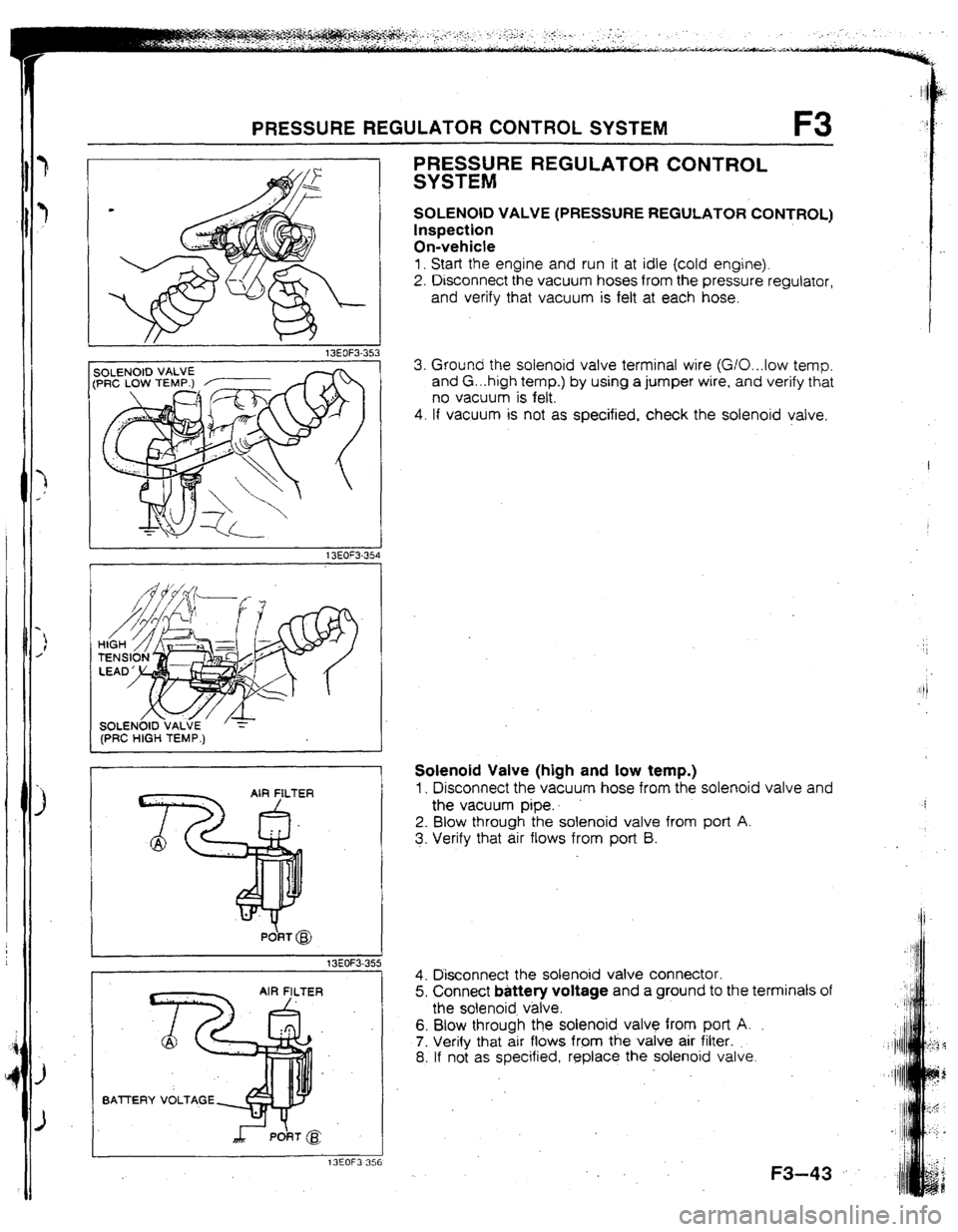
PRESSURE REGULATOR CONTROL
SYSTEM
SOLENOID VALVE (PRESSURE REGULATOR CONTROL)
Inspection
On-vehicte
1. Start the engine and run it at idle (cold engine).
2. Disconnect the vacuum hoses from the pressure regulator,
and verify that vacuum is felt at each hose.
3. Ground the solenoid valve terminal wire (G/O...low temp.
and G. ..high temp.) by using a jumper wire, and verify that
no vacuum is felt.
4. If vacuum is not as specified, check the solenoid valve.
Solenoid Valve (high and low temp.)
1, Disconnect the vacuum hose from the solenoid valve and
the vacuum pipe..
2. Blow through the solenoid valve from port A.
3. Verify that air flows from port B.
4. Disconnect the solenoid valve connector.
5. Connect battery voltage and a ground to the terminals of
the solenoid v&e.
6. Blow through the solenoid valve from port A.
7. Verify that air flows from the valve air filter.
8. If not as specified, replace the solenoid valve.
.
F3-43
Page 77 of 279
F3 CONTROL SYSTEM
CONTROL SYSTEM
PREPARATION
SST -
49 9200 162
49 GO?8 904
F3-44
Page 78 of 279
CONTROL SYSTEM F3
hT==TdI ,
USE CONNECTOR A 1
L
93GOF3-787 ENGINE CONTROL UNIT (ECU)
Inspection
1. Disconnect the ECU connectors.
2. Connect the SSTs {Engine Signat Monitor and Adapter) to
the ECU as shown.
3. Place the SST (Sheet) on the Engine Signal Monitor.
4. Measure the voltage at each terminal.
(Refer to pages F3-46 to F3-53.)
5. If any ECU terminal voltage is incorrect, check the related
input or output devices and wiring. If no problem is found,
replace the ECU. (Refer to page F3-2.)
t
1 13EOF3-358
r
TERMINALS
f. -I AANDB . Caution l Never apply voltage t.o terminals A and 8 of the SST.
! :OF3-359
F3-45
Page 79 of 279

F3 CONTROL SYSTEM
Terminal voltage
Reference date
Vs: Battery voltage
‘em&al Input Output Connected to Test condition Correct voltage Remark
1A - - Battery Constant VB
For backup
18 0 Main relay
Ignition switch OFF ov
(FUEL INJ relay) -
ON
V8
1C 0 lgnitlon switch While cranking Approx. 1 OV
(START) -
Ignition switch ON ov
10 0 Self-Diagnosis Test switch at SELF TEST
Wtth Self-
Checker Lamp illuminated for 3 sec. after ignition Approx. 5V
(monitor lamp) switch OFFdON Diagnosis Check-
er and System
lamp not iltuminated after 3 sec. V8 Selector
Test switch at 02 MONITOR with engine
idling Approx. 5V
Monitor lamp illuminated
Test switch at 02 MONITOR with engine
idling Vi3
Monitor lamp not illuminated
IE - - - - - -
IF
0 Self-Diagnosis Buzzer sounded for 3 sec. after ignition
Below 2SV
l With Seif-
Checker switch OFF-+ON
Diagnosis
(service code)
Buzzer not sounded after 3 set V0 ’ Checker and
Buzzer sounded Below 2.5V System Selector
l With System
Buzzer not sounded VB Selector test
switch at SELF
TEST
1G 0 igniter tgnition switch ON
ov
-
Idte
Approx. 0.2V
It-l 0
Solenoid valve Ignition switch ON
VB
(wastegate)
Idle
Approx. 2V ’ -
II
0 Fuel pump While cranking
Approx. 1 OV
resistor/relay -
Idle
8etow 1.5V
IJ 0 NC relay Ignition switch ON
VB
A/C switch UN at idle
Below 2.5V
. NC switch OFF at idle V3
-
IK 0 Diagnosis
connector
(TEN terminal) System Selector test switch at
02 MONITOR
System Selector test switch at
SELF TEST V0
-
8elow l*OV
1L - - - - - -
I
1M - - - - -
I -
lr ‘- l-7
f L.-
r
20 20 2M 2K 21 2G 2E 2c 2A IU 1S 10 10 ltvl tK II Ir; tE 1~ IA
1
22 2x 2v 2T ZR 2P 2N 2L 25 2H 2F 20 2B 1V IT 1R tP 1N IL 1J 1H IF 1~ 1~
1
J=3-46 --
4lways 4
--
AIways 4
--
Atways 1
--
Always 1
-a
Always ’
--
Always i
-e
Always I
2.5v
Always
Always (
-m
Always f
-a
Always 1
Always (
--
Always I
2.5V
Always 1
Always t
Always
--
Page 80 of 279

,,1
CONTROL SYSTEM F3 ‘1
Va: Battew voltage
Incorrect voltage Possible cause
Always OV
l ROOM IOA fuse burned l Open circuit In wiring from ROOM 10A fuse to ECU termina! 1A
Always OV
l Main relay malfunction l Open or short circuit in wiring from main relay to ECU terminal IB
Always OV (starter turns)
l Open or short circuit in wiring from ignition switch to ECU terminal IC
Always OV
Always VB
l Maln relay (FUEL INJ relay) malfunction l Open circuit in wiring from main relay to diagnosis connector terminal +B l Open or short circuit in wiring from diagnosis connector terminal MEN to
ECU terminal 1 D
l Poor connection at ECU connector l ECU malfunction
Always approx. 5V . ECU malfunction
Always below
2.5v
Always Ve -
-
No display on Self- * Main relay (FUEL INJ relay) malfunction
Diagnosis Checker
l Open circuit in wiring from main relay to diagnosis connector terminal + B
“88” displayed and
l Open or short clrcurt in wiring from diagnosis connector terminal FEN to
buzzer sounds con- ECU terminal tF
ti nuousl y
l Poor connection at ECU connector l ECU malfunction
Always QV
l Short circuit in wiring from igniter to ECU terminal 16
Always OV or VB
l Refer to Code No.42 Troubleshooting
(Refer to 323 4-Wheel Drtve Workshop Manual (12?9-IO-89L))
Always VB
Always OV
Always below
2.5V
Atways Ve I ’
l Fuel pump resistor/relay malfunction
l Open or short circurt in wiring from ECU terminal II to fuel pump resis-
tor/relay
A/C does not operate
l A/C reiay malfunction l Open circuit in wiring from ignition switch to A/C relay l Open circuit in wiring from A/C relay to ECU terminal 1J
A/C switch
OFF but l Short circuit in wiring from AIC relay to ECU terminal 1 J
A/C operates . ECU malfunction
l Poor connection at ECU connector l ECU malfunction
Always below 1 .OV a Short circuit in wiring from diagnosis connector terminal TEN to ECU termi-
nal 1K
Always Vs
l Open circuit In wiring from diagnosis connector terminal TEN to ECU terml-
nal IK
-
-
l Open circuit in winrig from diagnosis connector terminal GND to ground’
-
I -
.
. .
-. F3-47