Page 65 of 279
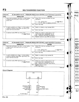
![MAZDA 323 1992 Workshop Manual Suplement F3 TROUBLESHOOTING GUIDE
3TEI ACTION
Is fuel line pressure correct at Idle?
*
Fuel line pressure: 265-314 kPa
12.7-3.2 kgf/cm’, 38-46 psi]
(Two vacuums hose to pressure regulator
disconnected MAZDA 323 1992 Workshop Manual Suplement F3 TROUBLESHOOTING GUIDE
3TEI ACTION
Is fuel line pressure correct at Idle?
*
Fuel line pressure: 265-314 kPa
12.7-3.2 kgf/cm’, 38-46 psi]
(Two vacuums hose to pressure regulator
disconnected](/manual-img/28/57055/w960_57055-64.png)
F3 TROUBLESHOOTING GUIDE
3TEI ACTION
Is fuel line pressure correct at Idle?
*
Fuel line pressure: 265-314 kPa
12.7-3.2 kgf/cm’, 38-46 psi]
(Two vacuums hose to pressure regulator
disconnected)
304-392 kPa [ 3.1-4.0 kgf/cm’, 44-57 psi 1
(Upper vacuum hose to pressure regulator
disconnected)
INSTALL CLAMPS Yes Go to next step
No Low pressure
Check fuel line pressure while pinching
fuel return hose
4 If pressure quickly Increases,
check pressure regulator
e If pressure gradually Increases,
check for clogging between fuel
pump and pressure regulator
If hose is not clogged, check fuel
pump maxrmum pressure
Connect System Selector to diagnosis connector
and set Test Switch to SELF TEST; is ignition
tlmlng at idle correct after warm-up?
Ignition timing (BTDC): 10 f lo Yes Go to next step
No Adjust tgnrtkon system
8 Dtsconnect water thermosensor connector; does
engine condrtlon Improve? Yes Replace water thermosensor
No
Try known good ECU. does condltlon
Improve?
w page F3-13
Go to next step
Check if injector resistance is OK
w page F3-42 9 Is jqector operating sound heard at Idle?
Yes
No
Resistance: Approx. 2.11 Q
(at 20°C 168*F])
4 If it is, check wlnng
(ECU - Injector)
c3 If it Is not, replace injector
Go to next step IO
Yes Is engine compressron cprrect?
w Section G
No
Engine compression:
1059 kPa 110.8 kgf/cm2, 152 psi)-300 rDm
is strong blue spark vrslble at each disconnected
hrgh-tension lead?’ Check engine
3 Section B2
17
Yes Go to next step
No Check high-tension lead
w Section G
c3 If UK, check distrrbutor cap and
rotor
3 If not OK, replace htgh-tensron lead
Try known good ‘ECU: does condrtron
Improve7
w page F3-3 12 Are spark plugs.OK?
w Section G
l Wear and carbon butld up l Piug gap l Damage Yes
NO
Clean, adjust
13EOi3.334
F3-32.
Page 66 of 279
![MAZDA 323 1992 Workshop Manual Suplement TROUBLESHOOTING GUlbE F3 1
14 IDLE MOVES UP AND DOWN/IDLE HUNTS
IESCRLP-
l Engine speeds up and down periodically at idle
UON
TROUBLESHOOTING HINTS]
B Idle switch (En throttle sensor) OFF at idl MAZDA 323 1992 Workshop Manual Suplement TROUBLESHOOTING GUlbE F3 1
14 IDLE MOVES UP AND DOWN/IDLE HUNTS
IESCRLP-
l Engine speeds up and down periodically at idle
UON
TROUBLESHOOTING HINTS]
B Idle switch (En throttle sensor) OFF at idl](/manual-img/28/57055/w960_57055-65.png)
TROUBLESHOOTING GUlbE F3 1
14 IDLE MOVES UP AND DOWN/IDLE HUNTS
IESCRLP-
l Engine speeds up and down periodically at idle
UON
TROUBLESHOOTING HINTS]
B Idle switch (En throttle sensor) OFF at idle
3 Air leakage
3 Fuel injection amount Inconstant
. Poor contact point inside airflow meter
9 Poor ignitron
rEP[ INSPECTION
I is “00” displayed on Self-Dragnosis Checker
with ignrtron swatch ON?
SYSTEM SELECT: i I ACTfON
Yes Go to next step
NO Service Code No. displayed
Check for cause (Refer to specified
check sequence) c=;r page F3-16
“86” flashes
Check ECU terminal IF vottage csr page F345
Voltage: Battery voltage
W: SELF TEST (ignition switch ON)
SELECT SW: A
.d P/ e If OK, replace ECU CT page F3-3
c3 If not OK, check wrrjng
(ECU - Self-Dlagnosls Checker)
2 Is intake manrfold vacuum correct at idle? Yes Go to next step
Intake manifold vacuum:
More than 450 mmHg { 17.7 inHg )
No Low vacuum
Check for air leakage at intake air
system
3 Is air cleaner element clean? Yes Go to next step
No Replace abr cleaner element
4 Disconnect each hrgh-tension lead at idie; does Yes Go to next step
engine speed decrease equally at each cylinder?
No Go to Step 8
5 Are ECU terminal voltages OK? Yes Go to next step
(especially 20, 2Q, 20) -
rI7 page F345 No
Check for cause
6 Connect System Selector to diagnosis connector Yes Go to next step
and set Test Switch to SELF TEST; is ignition
timing at idle correct after warm-up?
Ignition timing (BTDC): f 0 f la
No Adjust ignition timing
._
. F3-33
Page 67 of 279
TROUBLESHOOTING GUIDE
(at 20% [SS*F])
If It is, check wiring
e If OK, check distributor cap and
rotor
e If not OK, replace high-tensjon lead
12 Are spark plugs UK? Yes Is engine compresston correct? w Section 82
w Section G
. Wear and carbon burld up Engine compression: l Plug gap 1059 kPa 110.8 kgf/cm*, 352 psi I-300 rpm l Damage
4 If OK, go to next step
4 If not OK, check for cause
w Section 82
c
NO Clean, adjust
13 Check for injector leakage Yes
Replace injector
No Go to next step
14 Try known good ECU: does condition improve?
w page F3-45
----- Am.*
F3-34
~ROlJ8L Engine so:
3 Idle-sp.
T> fuel-cL
Page 68 of 279
![MAZDA 323 1992 Workshop Manual Suplement TROUBLESHOOTING GUiDE F3
15 ENGINE STALLS ON DECELERATION
IESCRIP-
l Engrne unexpectedly stops running dunng or after deceleration
[iON l Idle condition normal.
TROUBLESHOOT1NG HtNTS]
ingrne spe MAZDA 323 1992 Workshop Manual Suplement TROUBLESHOOTING GUiDE F3
15 ENGINE STALLS ON DECELERATION
IESCRIP-
l Engrne unexpectedly stops running dunng or after deceleration
[iON l Idle condition normal.
TROUBLESHOOT1NG HtNTS]
ingrne spe](/manual-img/28/57055/w960_57055-67.png)
TROUBLESHOOTING GUiDE F3
15 ENGINE STALLS ON DECELERATION
IESCRIP-
l Engrne unexpectedly stops running dunng or after deceleration
[iON l Idle condition normal.
TROUBLESHOOT1NG HtNTS]
ingrne speed drops too much when releasrng accelerator
3 Idle-speed misadjustment @I Loose connector disconnected by force of deceleration
3 Fuel-cut contrd malfunction
TEP lNSPECTlON ACTION
1 1s idle condition normal? Yes Go to next step
tdle speed: 800 f 50 rpm (in neutral)
NO Adjust or perform Troubleshooting, Nos.
8-I 1 “ROUGH IDLE”
(Refer to Workshop Manual
(1203-I o-89F))
2 Is “00” displayed on Self-Diagnosis Checker Yes Go to next step
with ignition switch ON?
SYSTEM SELECT: 1 NO Service Code No. displayed
Check for cause (Refer to specified
check sequence) ET page F3-16
“88” flashes
Check ECU termrnal 1 F voltage
Voltage: Battery voltage
(ignition switch ON) r;r page F346
W:SELFTEST
e If OK, replace ECU CI page F3-3
4 If not OK, check wirtng
(ECU - Self-Diagnosis Checker)
3 Does Self-Diagnosis Checker Monitor Lamp with Yes Go to next step
lgnttlon switch UN show that switches operate
correctly?
NO Lamp not ON or OFF with specified
switch
Check for cause (Refer to specified
check sequence)
W: SEtF TEST Lamp slways ON
Check wiring between
(ECU terminal 1 D - Self-Diagnosis
Checker)
4 Are ECU ?erminal voltages OK? Yes Go to next step
(especially IV, 20, 20, ZU, 2V.
and 20) v page F346 No
Check for cause
5 Check for poor connection of foltowing parts YC?S Repair or replace
l ignrtion coil l Igniter l Olstribdor l High-tension lead
NO Go to next step l Injector. l Injector resistor l Ctrcuit-opening relay . l ECU
F3-35
Page 69 of 279

F3 TROUBLESHOOTING GUIDE
STEP INSPECTION ACTlON
6 Is dashpot correctly adjusted? Yes Go to next step
c
Dashpot set speed: Approx. 3,500 rpm
No Adjust dashpot
7
Try known good ECU; does condition
Improve?
w page F3-3
13EOF3-336
16 ENGINE STALLS SUDDENLY (INTERMITTENT)
DESCRIP.
l Engine intermittently stops running
TION l Before stalling, engine conditron is OK
TROUBLESHOOTING HINTS]
@ intermittently no spark or no fuel injection caused by ve-
hlcle vibratron, acceleratton, or deceleration
l Poor connectlon in wiring harness
iTEP INSPECTION ACTfON
1 Is “00” displayed on Self-Oiagnoss Checker Yes Go to next step
with lgnltlon swrtch ON?
NO Service Code No. displayed
Check for cause (Refer to speclfled
check sequence).
Note CT page F3-16
l When checking wiring harness and
connectors, tap, move, and wiggle
suspect sensor and/or harness to
recreate problem
“88” flashes ’
Check ECU terminal IF voltage
Voltage: Battery voltage
{ignition swttch ON) w page F3-45
4 If OK, replace ECU
4 If not OK, check wiring
(ECU - Self-Diagnosis Checker)
2 Check for poor connection of foliowrng parts
Yes Reparr or replace
l lgnltfon coil l Igniter l Distributor l t-flgh-tensron lead
No Go to next step l Injector l Injector reststor l Circutt-opening relay l ECU
3 Are ECU terminal voltages OK? Yes Go to Troubleshbotrng No. 2
(especially 16, 2A, 2B, and 2C) .“CRANKS NORMALLY BUT WILL NOT
w page F3-45 START (NO COMBUSTION)”
w page F3-20
Note
. No Check for cause
l When. checking voltages, tap, move, and
wiggle harness and connector to recreate
problem
* lrlrl m-7
F3-36
7.8-l
Page 70 of 279

F3 II TURBOCHARGER CONTROL SYSTEM ‘1
1’
:j
TURBOCHARGER CONTROL
SYSTEM
TURBOCHARGER
Re’inovaf / Installation
Caution
l Be careful of the following points after turbocharger removal.
l Do not carry the turbocharger by the actuator rod or actuator hose.
l Do not drop the turbocharger.
l Set the turbocharger down with the turbine shaft horizontat.
l Cover the intake, exhaust, and oil passages to prevent dirt or other material from entering
the turbocharger.
l Use the specified new studs when installing the turbocharger.
1, Disconnect the negative battery cable.
2. Raise the vehicle and support it on safety stands.
3. Remove the undercover.
4. Orain the engine coolant.
5. Remove in the order shown in the figure, referring to Removal Note.
6. Install in the reverse order of removal, referring to Installation Note.
I-- 7.8-1 1 N-m ~80-110 kgfcm. 69-96 idbf j
3946 13.94.7, 2% 3842 13.94.3, 28-
31--46 13.2-4.7, 23-341
T, REPLACE .
12-18 1 f-2-1.8, 8.7-13 I
GASKET, REPLACE
19-26 1 t .9-2.6, 14-19 1
7.6-11 Mm t80-?lO kgfcm, 69-95 hlbfl
~-t-n 1 kgf-m, Wlbt]
13EOF3 3.31
F3-3i
Page 71 of 279

F3 TURBOCHARGERCONTROLSYSTEM
1. Radiator
2. Insulator 3. Air hose, and air pipe
4. Oxygen sensor connector
5. Front exhaust pipe
13EOF534
F3-38 6. Water hose
7. Oil pipe
8. Exhaust manifold and turbocharger
Removal Note ,.........I.....f.~.~l....... II.I.... below
Installation Note . . . . , , l.. . . . . . . , ,.. ,..*, , . . . . . . . . . below
13EOF3-339
Removal Note Exhaust
manifold and turbocharger 1. Remove the exhaust manifold and the turbocharger as an
assembly.
2. Separate the turbocharger assembly from the exhaust
manifold.
Installation Note
Exhaust manifold and turbocharger’ I I Remove .all old gaskets and
sealant. 2. Install new gaskets.
3. Supply 25 cc ( 1.5 cu in ] of oil through the oil passage
of the turbocharger.
4. Mount the turbocharger assembly to the exhaust manifold.
5. Install the turbocharger and the exhaust manifold assem-
bly to the engine and loosely tighten the nuts.
6. Install the bracket and the front exhaust pipe, and tighten
the turbocharger mounting nut%
WASTEGATE SOLENOD VALVE
Caution
l The wastegate solenoid valve must be replaced with
the turbocharger, it cannot be replaced by itself.
Inspection 1. Disconnect the connector.
2. Measure the resistance of the solenoid valve.
Resistance: 35-45 !‘l (at 20°C f68OFj) 3. M not as specified, replace the wastegate solenoid valve and
turbocharger as an assembly, if necessary.
(Refer to page F3-37.)
3. Instc
Page 72 of 279
TURBOCHARGER CONTROL SYSTEM F3
INTERCOOLER
Removal / Installation
1 I Remove the front bumper. (Refer to Section S.)
2. Remove in the order shown in the figure.
3. Install in the reverse order of removal.
7-i-11 N-h l80-110 kgfem, 69-95 In-lbf 1
1.
Air hose 2. Intercooler
wrn 1 kgf-m, ft-lbf I
13EOF3-34: