Page 193 of 279
Gl Troubleshooting
Handling connectors
Caution
l Be sure to grasp the connectors, not the wires, when disconnecting them.
Improperly engaged
connectors will cause
poor terminal contact. A loose terminal Will
cause poor terminal 1 Baise the rear
2.Lift the tab with a
thin piece of metal
and remove the
Lift the tab with a thin
piece of metal and
there is no looseness in connector when engaged.
the female terminal.
1 .Raise the cover.
P.Lift the terminal to
B-Make sure the
terminal is securely
mounted in the
connector when
Pull lightly on individual
wires to check that they
are secured in the 1 Raise the cover.
2.Remove A.
3.Lift the tab with a
thin piece of metal
and remove the
Page 194 of 279

Troubleshooting
Using electrical measuring equipment
Equipment USe
Test lamp Test to find open or shorted
H circ”its. operation Handling precautions 0 Connect the test lamp l Test lamps use 12V 1.4W
between the circuit being
or 3.4W bulbs or light-emitting
measured and a ground.
diodes (LEDs). Using .a large-
l The lamp will light if the circuit
capacity bulb may damage the
is energized to the point
CPU.
tested.
I? ‘s
n
Jumper wire
Used to create a temporary 0 Connect the jumper wire
l Do not connect the jumper
circuit. between the terminals of a wire from the power source
circuit to bypass a switch. line to a ground; this may
4 cause burning or other
b damage to harnesses or
electronic components.
M
Voltmeter
Used for measuring the voltage
l Connect the voltmeter in
of a circuit to find possible opens *Connect the positive (+) probe
parallel with the circuit.
or shorts.
to the Point where Voltage is to 0 Set the range to the desired
be measured and the negative
voltage.
(-) probe to a ground.
*Use the service hole when
measuring the voltage at the
diagnosis connector.
‘$$
‘, i_ I/
*Tie a thin wire to the positive
(+) probe to access narrow
terminals.
Ohmmeter
l Zero the ohmmeter.
Used to find opens and shorts in *Zero the meter after switching
the circuit, to confirm continuity l-.&j
to the measuring range.
and to measure resistance. -*-.
0 Before using the ohmmeter,
l Verify that voltage is not make sure the ignition switch
applied to the circuit. is off or the negative (-)
l Connect the probes between battery cable is disconnected
two points in a circuit. _ to prevent burning or
otherwise damaging the
ohmmeter.
Ammeter
l Connect the ammeter in series l Set the range to the desired
Used to check alternator output,
with the circuit by touching the amperage.
current supplied to the starter,
and dark current within a circuit. positive (+) probe to the l Connect the ammeter in series
power-side terminal and the with the circuit. The ammeter
Note
Dark current is the constant flow negative (-) probe to the
ground-side terminal. may be burned or otherwise
damaged if it is connected in
parallel.
of current while the ignition
switch is OFF.
13
Page 195 of 279
Troubleshooting
Measuring voltage
lgnlgon switch
Voltmeter
Groind 2 -
Ground 1 Test lamp
or
If Connect a voltmeter or test lamp to the measuring points.
‘6 : Test lamp ON
x : Test lamp OFF
Weasuring voltage of connectors Poor contact
A voltmeter probe may momentarily connect a terminal wher
inserted into the connector and give an erroneous reading
when checking for improperly engaged connectors, poor
terminal contacts, or loose terminals.
Measuring voltage of ground
Touch the voltmeter probe to the ground wire when
checking the ground circuit.
Poor contact OK
14
Page 196 of 279

Troubleshooting GI
Measuring continuity/resistance
Touch the ohmmeter probes to the switch terminals to check
Verify the operating state of the switch before checking
continuity because readings vary accordingly.
Note Continuity is checked according to the direction of the positive
(+) and negative (-) probes ofihe ohmmeter in the circuit
containing the diode.
Connection
I Continuity
Yes
The negative (- ) probe of the ohmmeter is
connected to the positive terminal of the internal
ohmmeter battery, the positive (+) probe to the
negative terminal of the battery. No
Connect the ohmmeter probes to the sensor or solenoid valve
terminals to check resistance.
Caution
Verify the operating state of the sensor before checking
resistance because readings vary accordingly.
1. Short between the terminals with a jumper wire to discharQe
the capacitor.
2. Set the ohmmeter range to xl Ok R and connect it to the
capacitor terminals.
3. The capacitor is good if the needle of the ohmmeter swings
once and returns to its original position.
15
Page 197 of 279

GI Troubleshooting
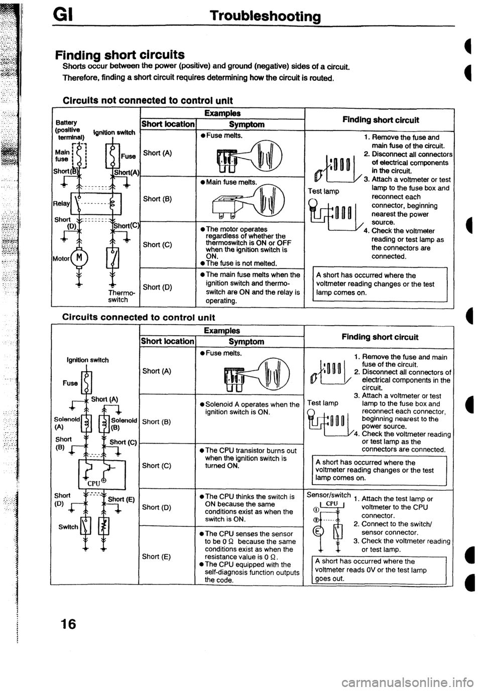
FindIng short circuits
Shorts occur between the power (positive) and ground (negative) sides of a circuit.
Therefore, finding a short circuit requires determining how the circuit is routed.
Circuits
not connected to control unit
I
Examples
ihort location 1 SvmWom
I Battery
,pOSlhl
terminal) lgnitbn switch
I Finding short circuit
4
1. Remove the fuse and
main fuse of the circuit.
2. Disconnect ail connecton
Of electrical components in the circuit.
3. Attach a voltmeter or test
Motor
M
Qi!
Short (A)
Short (8)
Short (C)
Short (0) l The motor operates
regardless of whether the
thermoswitch is ON or OFF
when the ignition switch is ..-..
ON. -
@The fuse is not melted.
0 The main fuse melts when the
ignition switch and thermo-
switch are ON and the relay is
operating.
lgnitlon switch
Switch short locatior
Short (A)
Short (B)
Short (C) Test lamp lamp to the fuse box and
reconnect each connector, beginning
nearest the power
, source. Circuits connected to control unit
1 Examples
Symptom
l Fuse melts.
Short (D)
Short (E) 14. Check the voltmeter
reading or test lamp as
the connectors are
connected.
l solenoid A operates when the
ignition switch is ON.
l The CPU transistor burns out
when the ignition switch is
turned ON.
l The CPU thinks the switch is
ON because the same
conditions exist as when the
switch is ON.
@The CPU senses the sensor
to be 0 Q because the same
conditions exist as when the
resistance value is 0 Q.
l The CPU equipped with the
self-diagnosis function outputs
the code. l-
Finding short circuit
1. Remove the fuse and main
fuse of the circuit.
2. Disconnect ail connectors oi
electrical components in the
circuit.
rest lamp 3. Attach a voltmeter or test
lamp to the fuse box and
reconnect each connector,
beginning nearest to the
power source.
Check the voltmeter reading
or test lamp as the
connectors are connected.
Sensor/switch
1. Attach the test lamp or
voltmeter to the CPU
connector.
2. Connect to the switch/
sensor connector.
3. Check the voltmeter reading
voltmeter reads OV or the test lamp
16
Page 198 of 279
This page left intentionally blank
Page 199 of 279
18 Y
l GROUND POINTS
WIRING ORDER INTO JOINT CONNECTOR MAY BE CHANGED
Jc-0 1 JOINT CONNECTOR F) JC-02 JOINT CONNECTOR (F)
JC-03 JOINT CONNECTOR (F)
m 6-l ”
6-n e-a
B B B B B 0 B B B B
B
0 B/G B B
JC-04 JOINT CONNECTOR (EM)
~~-06 JOINT CONNECTOR (EM)
JC-09 JOINT CONNECTOR (R)
a ”
*
*
0 FRONT
&Ii UNIT
@
1 0 5
88 0 5 EMISSION
//
//
//
@
//
JC-06
Page 200 of 279
HARNESS SYMBOL : B
F) m (E) m (0 m 03 +++ PW E (IN) E (W
*** (EM) E (INJ)
19