Page 395 of 1216

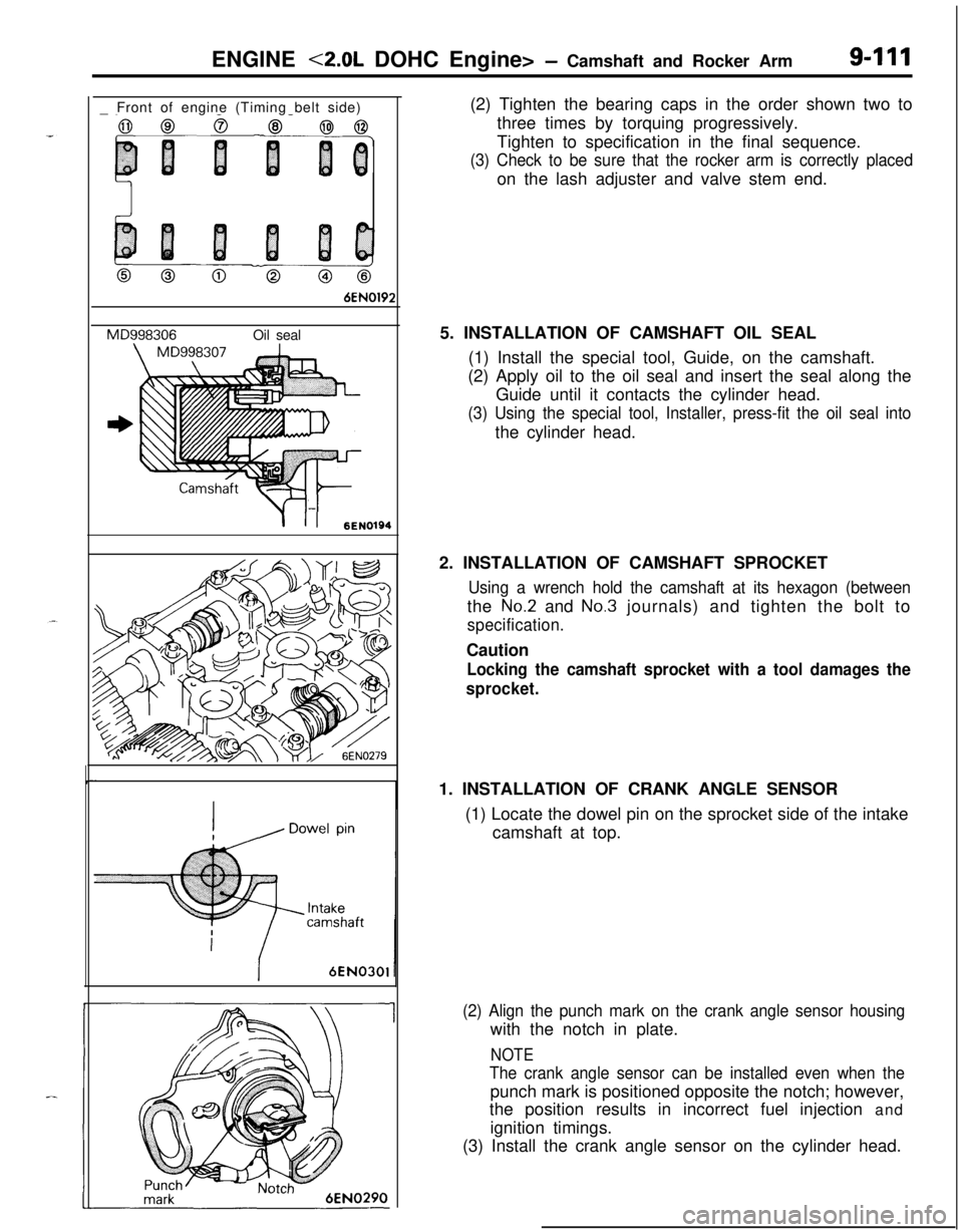
ENGINE <2.0L DOHC Engine> - Camshaft and Rocker Arm9-111_ Front of engine (Timing belt side)
0 Co@
6EN0192
MD998306Oil seal
-
Y-II6ENI01946EN030’
1(2) Tighten the bearing caps in the order shown two to
three times by torquing progressively.
Tighten to specification in the final sequence.
(3) Check to be sure that the rocker arm is correctly placedon the lash adjuster and valve stem end.
5. INSTALLATION OF CAMSHAFT OIL SEAL
(1) Install the special tool, Guide, on the camshaft.
(2) Apply oil to the oil seal and insert the seal along the
Guide until it contacts the cylinder head.
(3) Using the special tool, Installer, press-fit the oil seal intothe cylinder head.
2. INSTALLATION OF CAMSHAFT SPROCKET
Using a wrench hold the camshaft at its hexagon (betweenthe
No.2 and No.3 journals) and tighten the bolt to
specification.Caution
Locking the camshaft sprocket with a tool damages the
sprocket.1. INSTALLATION OF CRANK ANGLE SENSOR
(1) Locate the dowel pin on the sprocket side of the intake
camshaft at top.
(2) Align the punch mark on the crank angle sensor housingwith the notch in plate.
NOTE
The crank angle sensor can be installed even when thepunch mark is positioned opposite the notch; however,
the position results in incorrect fuel injection and
ignition timings.
(3) Install the crank angle sensor on the cylinder head.
Page 397 of 1216

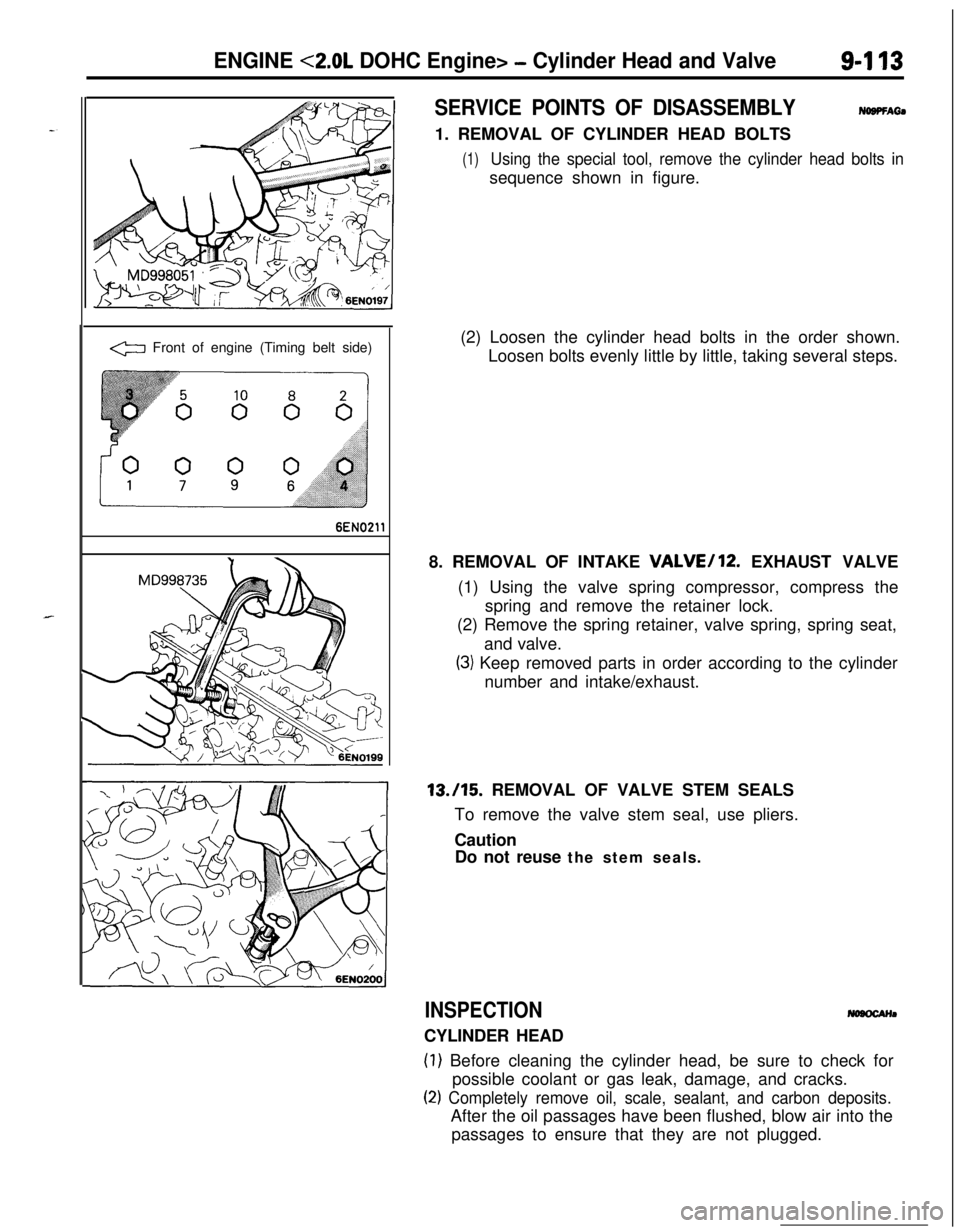
ENGINE <2.0L DOHC Engine> - Cylinder Head and Valve9-l 13
.
.
a Front of engine (Timing belt side)
6EN0211
SERVICE POINTS OF DISASSEMBLYNOBPFAti1. REMOVAL OF CYLINDER HEAD BOLTS
(1)Using the special tool, remove the cylinder head bolts insequence shown in figure.
(2) Loosen the cylinder head bolts in the order shown.
Loosen bolts evenly little by little, taking several steps.
8. REMOVAL OF INTAKE
VALVE/12. EXHAUST VALVE
(1) Using the valve spring compressor, compress the
spring and remove the retainer lock.
(2) Remove the spring retainer, valve spring, spring seat,
and valve.
(3) Keep removed parts in order according to the cylinder
number and intake/exhaust.13./15. REMOVAL OF VALVE STEM SEALS
To remove the valve stem seal, use pliers.
Caution
Do not reuse the stem seals.
INSPECTIONCYLINDER HEAD
(1) Before cleaning the cylinder head, be sure to check for
possible coolant or gas leak, damage, and cracks.
(2) Completely remove oil, scale, sealant, and carbon deposits.After the oil passages have been flushed, blow air into the
passages to ensure that they are not plugged.
Page 400 of 1216
9416
I
ENGINE <2.0L DOHC Engine> - Cylinder Head and Valve
I1. INSTALLATION OF CYLINDER HEAD BOLTS
(1) Using the special tool, tighten the cylinder head bolts.
G Front of engine (Timing belt side)(2) Tighten the cylinder head bolts in the sequence shown.
Each bolt should be tightened in two to three steps,
torquing progressively. Tighten to specified torque in
the final sequence.
Page 414 of 1216

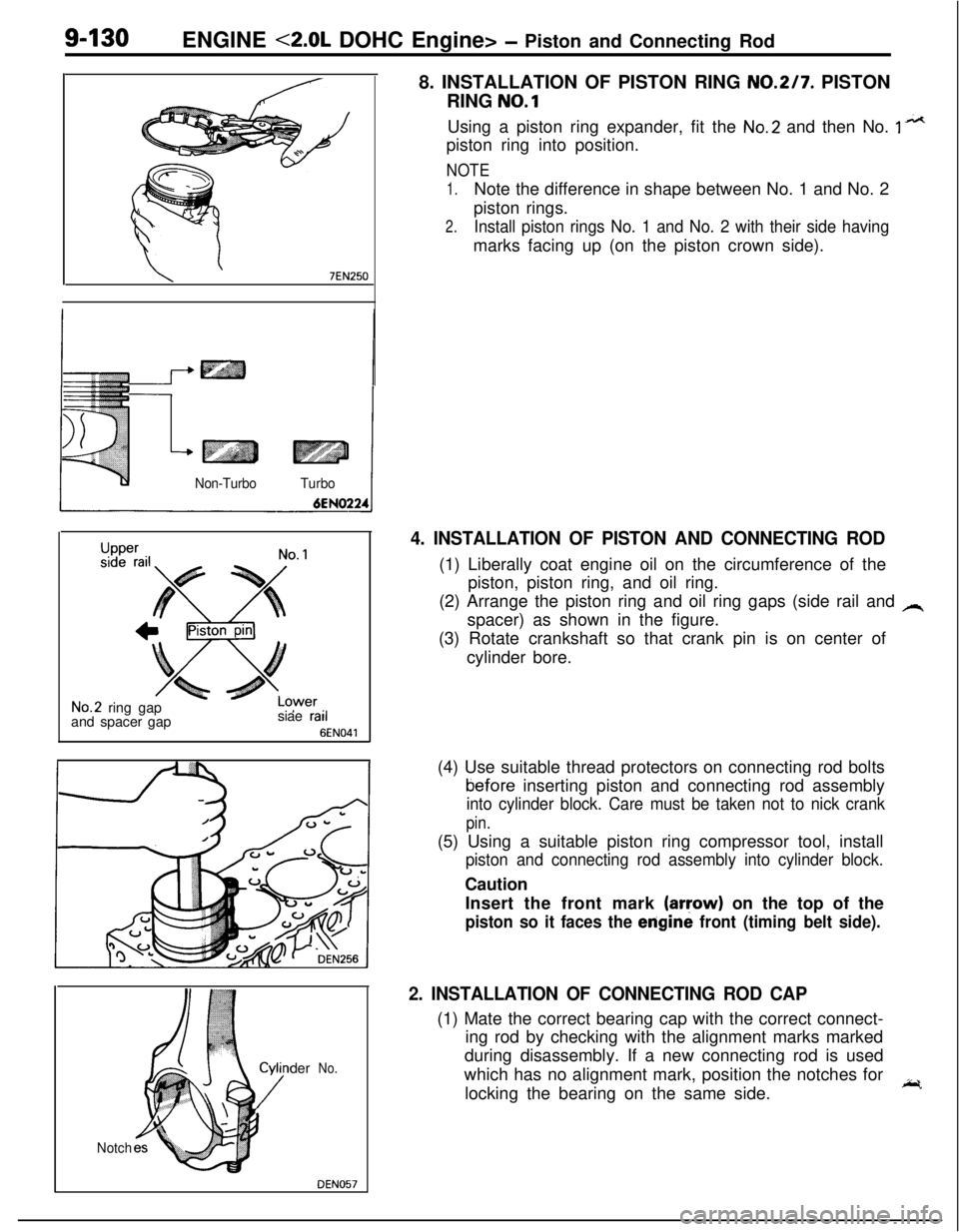
9-130ENGINE <2.0L DOHC Engine> - Piston and Connecting Rod
8. INSTALLATION OF PISTON RING
NO.217. PISTON
RING
NO.1
\ ’7EN250
Non-TurboTurbo
Upper
LCsiae rail
6
3wer’ ‘I
EN041
No.2 ring gap
and spacer gap
der
No.
Notch
DEN057Using a piston ring expander, fit the
No.2 and then No. 1 n*tpiston ring into position.
NOTE
1.Note the difference in shape between No. 1 and No. 2
piston rings.
2.Install piston rings No. 1 and No. 2 with their side havingmarks facing up (on the piston crown side).
4. INSTALLATION OF PISTON AND CONNECTING ROD(1) Liberally coat engine oil on the circumference of the
piston, piston ring, and oil ring.
(2) Arrange the piston ring and oil ring gaps (side rail and
Aspacer) as shown in the figure.
(3) Rotate crankshaft so that crank pin is on center of
cylinder bore.
(4) Use suitable thread protectors on connecting rod boltstiefore inserting piston and connecting rod assembly
into cylinder block. Care must be taken not to nick crank
pin.(5) Using a suitable piston ring compressor tool, install
piston and connecting rod assembly into cylinder block.Caution
Insert the front mark
(aryow) on the top of the
piston so it faces the erigine front (timing belt side).
2. INSTALLATION OF CONNECTING ROD CAP(1) Mate the correct bearing cap with the correct connect-
ing rod by checking with the alignment marks marked
during disassembly. If a new connecting rod is used
which has no alignment mark, position the notches for
locking the bearing on the same side.
I;r.
Page 419 of 1216
ENGINE <2.0L DOHC Engine> -Crankshaft, Flywheel and Drive Plate g-135
‘I. _
Front ofengine
(Timing
belt side)
BEN02
DEN063
6ENO48-
11. INSTALLATION OF BEARING CAP
(1) Verify the correct identification mark and the directionof the arrow for installation.
(2) After installing the bearing caps, make sure that the
crankshaft turns smoothly and the end play is correct. Ifthe end play exceeds the limit, replace crankshaft
bearings.Standard value:
0.05-0.18 mm (.0020-.0071 in.)
Limit: 0.25 mm
(.0098 in.)
10. INSTALLATION OF OIL SEALUsing the special tool, press-fit the oil seal into the
crankshaft rear oil case. Use a new oil seal.9. INSTALLATION OF OIL SEPARATOR
Force the oil separator into the oil seal case so that the oilhole in the separator is directed downward (arrow in
illustration).
Page 649 of 1216

STEERING
CONTENTSNISAA-
MANUAL STEERINGGEAR BOX.................21
POWER STEERINGGEAR BOX...................
28
POWER STEERING
HOSES........................
46
POWER STEERING OIL PUMP....................39
SERVICE ADJUSTMENT PROCEDURES
>...........................7
Steering Angle Check..............................7
Steering Wheel Centering.........................8
Steering Wheel Free Play Check.............:..7Tie Rod End Ball Joint Starting Torque
Check..................................................8Tie Rod End Ball Joint Variation Check
(Shaft direction).....................................7
SERVICE ADJUSTMENT PROCEDURES
< POWER STEERING >.............................
10
Bleeding...............................................13Fluid Level Check...................................
12
Fluid Replacement..................................12
i;,
Oil Pressure Switch Check........................15
Oil Pump Pressure Test...........................14
Stationary Steering Effort Check.................11Steering Angle Check..............................
10
Steering Wheel Centering.........................1 1
Steering Wheel Free Play Check................10Steering Wheel Return to Center Check.......
11Tie Rod End Ball Joint Starting Torque
Check..................................................10Tie Rod End Bail Joint Variation Check
(Shaft direction).....................................10
V-Belt Tension Check..............................12
SPECIAL TOOLS......................................6
SPECIFICATIONS.....................................2;
General Specifications..............................2
Lubricants.............................................5
Sealants and Adhesives............................5
Service Specifications.............‘................2
Torque Specifications,. . . . . . . . . . . . . . . . . ..*..........3
STEERING WHEEL AND SHAFT.................. 16
Page 650 of 1216
Page 660 of 1216

19-12STEERING - Service Adjustment Procedures
Pressure ofWater pump
pulleyOlA0059Fluid fluctuation
While engine
runningWhile enginestopped13uo139
Return hoseVinyl hose
x ,3Ao,42-
V-BELT TENSION CHECKNlSFliAl
1.Check to be sure that the belt is not damaged and that the
V-belt is correctly attached to the groove of the pulley.
NOTE, If there is abnormal noise or belt slippage, check the belt
tension and check for unusual wear or abrasion, or damage,
of the
pullev contact surface, and for scars or scratches onthe
pulley.2.
Press in V-belt at the illustrated position with about 100 N
(22 Ibs.) and measure deflection.
Standard value: 6-9 mm
1.26.35 in.)
3. If there is a deviation from the standard value range, make
an adjustment of the belt tension by following the procedures
described below.
(1) Loosen bolts A, B and C (for holding the oil pump).
(2) Place a bar or similar object against the body of the oil
pump, and, while manually providing the suitable
amount of tension, adjust the amount of
flexion of the
belt.
(3) Tighten bolts A, B and C (for holding the oil pump).
(4) Check the amount of flexion of the belt; readjust if
necessary.
CautionThe check should be made after turning the engine
one time or more in the regular direction of rotation (tothe
dght).
FLUID LEVEL CHECKNlSFIAI
1.Park the vehicle on a flat, level surface, startthe engine, andthen turn the steering wheel several times to raise the
temperature of the fluid to approximately
50-60°C
(122-140°F).2. With the engine running, turn the wheel all the way to the
left and right several times.3. Check the fluid in the oil reservoir for foaming or milkiness.
Check the difference of the fluid level when the engine is
stopped, and while it is running. If the fluid level changes
considerably, air bleeding should be done.
FLUID REPLACEMENTNlSFJAJ
1.Raise the front wheels on a jack, and then support them with
rigid racks.2. Disconnect the return hose connection.
3.Connect a vinyl hose to the return hose, and drain the oil into
a container.