Page 338 of 1216
ENGINE - Cylinder Head and ValveSERVICE POINTS OF DISASSEMBLY
1. REMOVAL OF CYLINDER HEAD BOLTS
3EN123Front of engine (Timing belt side)
c
1 EN025
3EN324Loosen the bolts in the order shown.
Loosen them little by little and uniformly.
5./9. REMOVAL OF RETAINER LOCKS(1) Using the special
tool, remove the retainer locks.
(2) Keep the removed retainer locks valve by valve so that
they can be reinstalled in their original positions.
A
13.115. REMOVAL OF VALVE STEM SEALRemove the stem seals with pliers. Do not reuse the valve
stem seal.
Page 347 of 1216

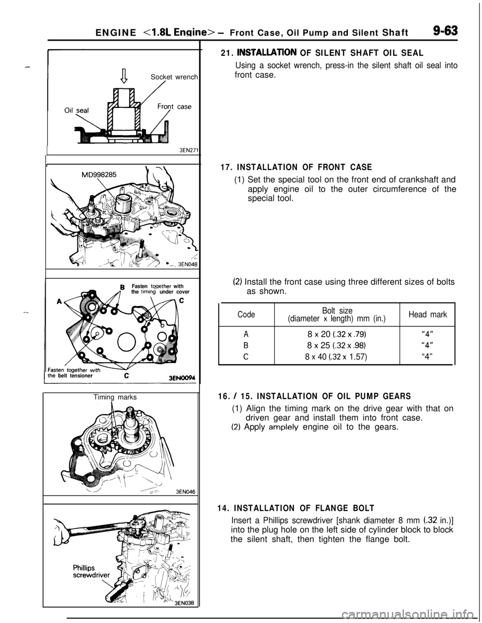
ENGINE <1.8L Engine> -Front Case, Oil Pump and Silent Shaft9-63
aSocket wrench/
3EN271
MD998285R
Fasten toqether with
the timtins under cover
C
belt tensioner3ENOOWTiming marks
16. / 15. INSTALLATION OF OIL PUMP GEARS(1) Align the timing mark on the drive gear with that on
driven gear and install them into front case.
(2) Apply amplely engine oil to the gears.
3EN046
21. INSTALLATlON OF SILENT SHAFT OIL SEAL
Using a socket wrench, press-in the silent shaft oil seal intofront case.
17. INSTALLATION OF FRONT CASE(1) Set the special tool on the front end of crankshaft and
apply engine oil to the outer circumference of the
special tool.
(2) Install the front case using three different sizes of bolts
as shown.
Code
A
B
C
Bolt size
(diameter x length) mm (in.)8
x 20 (.32 x .79)8
x 25 (.32 x .98)
8 x 40 (32 x 1.57)
Head mark
“4”
“4”“4”
14. INSTALLATION OF FLANGE BOLT
Insert a Phillips screwdriver [shank diameter 8 mm (32 in.)]into the plug hole on the left side of cylinder block to block
the silent shaft, then tighten the flange bolt.
Page 352 of 1216

9-68ENGINE <1.8L Engine> - Piston and Connecting Rod
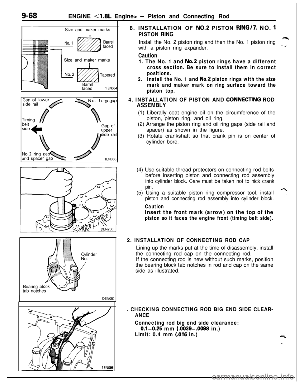
r-Size and maker marks
No. 1Barrel
faced
1
1 Size and maker marks
L
INo.2
ti2zza
Tapered
Barrelfaced
1 EN064
-1 No. 1 rina aarGap of
upper8. INSTALLATION OF
NO.2 PISTON RING/7. NO. 1
PISTON RINGInstall the No. 2 piston ring and then the No. 1 piston ring
with a piston ring expander.
Caution
1. The No. 1 and No.2 piston rings have a different
cross section. Be sure to install them in correct
positions.
2.Install the No. 1 and No.2 piston rings with the size
mark and maker mark on ring surface toward the
piston top.
4. INSTALLATION OF PISTON AND CONNECTlNG ROD
ASSEMBLY(1) Liberally coat engine oil on the circumference of the
piston, piston ring, and oil ring.
(2) Arrange the piston ring and oil ring gaps (side rail and
spacer) as shown in the figure.
(3) Rotate crankshaft so that crank pin is on center of
cylinder bore.
Bearing
bltab notches
DEN057(4) Use suitable thread protectors on connecting rod bolts
before inserting piston and connecting rod assembly
into cylinder block. Care must be taken not to nick crank
pin.(5) Using a suitable piston ring compressor tool, install
piston and connecting rod assembly into cylinder block.
Caution
Insert the front mark (arrow) on the top of the
piston so it faces the engine front (timing belt side).
2. INSTALLATION OF CONNECTING ROD CAPLining up the marks put at the time of disassembly, install
the connecting rod cap on the connecting rod.
If the connecting rod is new without such marks, position
the bearing block tab notches in rod and cap on the same
side as illustrated.
. CHECKING CONNECTING ROD BIG END SIDE CLEAR-
ANCE
Connecting rod big end side clearance:
0.1-0.25 mm (.0039-.0098 in.)
Limit: 0.4 mm (016 in.)
Page 355 of 1216

ENGINE - Crankshaft, Flwvheel and Drive Plate9-71
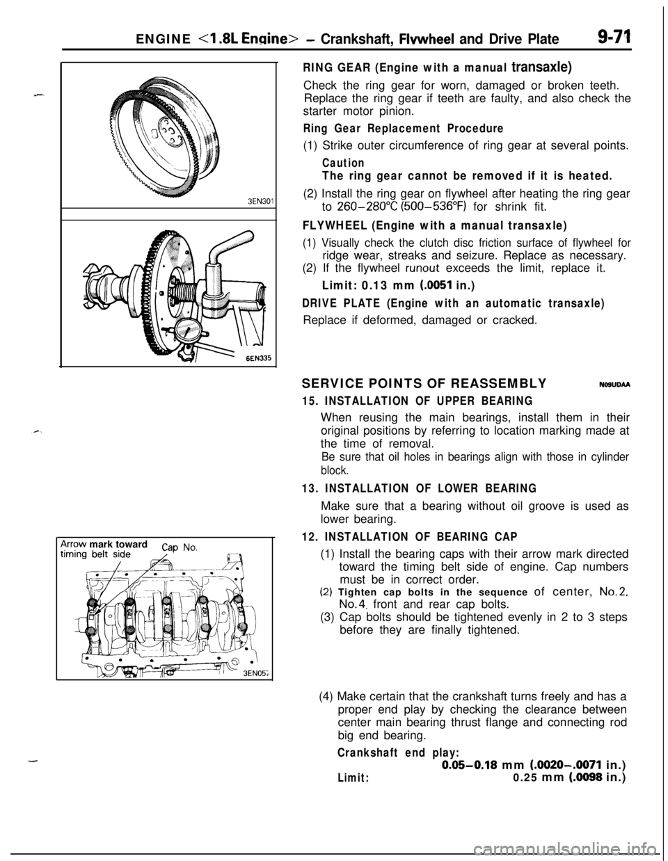
3EN30’lrrow mark toward
cap No,
I
RING GEAR (Engine with a manual transaxle)Check the ring gear for worn, damaged or broken teeth.
Replace the ring gear if teeth are faulty, and also check the
starter motor pinion.
Ring Gear Replacement Procedure(1) Strike outer circumference of ring gear at several points.
Caution
The ring gear cannot be removed if it is heated.(2) Install the ring gear on flywheel after heating the ring gear
to
260-280°C (500-536°F) for shrink fit.
FLYWHEEL (Engine with a manual transaxle)
(1) Visually check the clutch disc friction surface of flywheel forridge wear, streaks and seizure. Replace as necessary.
(2) If the flywheel
runout exceeds the limit, replace it.
Limit: 0.13 mm (0051 in.)
DRIVE PLATE (Engine with an automatic transaxle)Replace if deformed, damaged or cracked.
SERVICE POINTS OF REASSEMBLY
NOSUDAA
15. INSTALLATION OF UPPER BEARINGWhen reusing the main bearings, install them in their
original positions by referring to location marking made at
the time of removal.
Be sure that oil holes in bearings align with those in cylinder
block.
13. INSTALLATION OF LOWER BEARINGMake sure that a bearing without oil groove is used as
lower bearing.
12. INSTALLATION OF BEARING CAP(1) Install the bearing caps with their arrow mark directed
toward the timing belt side of engine. Cap numbers
must be in correct order.(2) Tighten cap bolts in the sequence of center,
No.2,
No.4. front and rear cap bolts.
(3) Cap bolts should be tightened evenly in 2 to 3 steps
before they are finally tightened.
(4) Make certain that the crankshaft turns freely and has a
proper end play by checking the clearance between
center main bearing thrust flange and connecting rod
big end bearing.
Crankshaft end play:
0.05-0.18 mm (.0020-.0071 in.)
Limit:0.25 mm (.0098 in.)
Page 368 of 1216

9-84ENGINE <2.0L DOHC Engine> -Camshafts and Camshaft Oil Seals
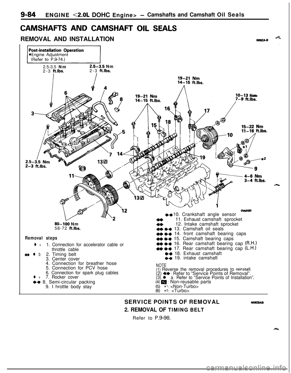
CAMSHAFR AND CAMSHAR OIL SEALSREMOVAL AND INSTALLATION
No8u-s
ppEJ=-j2.5-3.5 Nm
2.5-3.5 Nm
2-3 ft.lbs.2-3 ft.lbs.
lo-13 Nm
olmlzo++ 10. Crankshaft angle sensor
a*11. Exhaust camshaft sprocket80-100 Nm4*12. Intake camshaft sprocket
58-72 ftlbs.+e *+ 13. Camshaft oil seals
Removal steps+e e+ 14. front camshaft bearing caps41)
+4 15. Camshaft bearing caps
l +1. Connection for accelerator cable or+e +c 16. Rear camshaft bearing cap (R.H.)
throttle cable+e +4 17. Rear camshaft bearing cap (L.H.)
d+ l b2. Timing belt~~ 18. Exhaust camshaft
3. Center cover+q 19. intake camshaft
4. Connection for breather hose
5. Connection for PCV hose
NOTE
6. Connection for spark plug cables(1) Reverse the removal procedures to reinstall.(2) 4* : Refer to “Service Points of Removal”.l +7. Rocker cover
(3) l a : Refer to “Service Points of Installation”.~~ 8. Semi-circular packing(4) m : Non-reusable parts
9. I hrottle body stay
1:;*I: ~2:
SERVICE POINTS OF REMOVAL
No9zsAB
2. REMOVAL OF TIMING BELTRefer to P.9-98.
Page 371 of 1216

ENGINE <2.0L DOHC Engine> -Camshafts and Camshaft Oil Seals/Oil Pan and Oil Screen9-87
7. INSTALLATION OF ROCKER COVERApply a coating of the specified sealant where shown in
the figure, and then install the rocker cover to the cylinder
head assembly.
Apply sealant
mmin.)
Specified sealant: MOPAR Part No.4318034
or equivalent
olmO47
2. INSTALLATION AND ADJUSTMENT OF TIMING BELTRefer to
P.9-104.
1. ADJUSTMENT OF ACCELERATOR CABLERefer to GROUP 14-Service adjustment procedures.
OIL PAN AND OIL SCREENNO9HA-BREMOVAL AND INSTALLATION
/
/j<&(Refer to GROUP O-Maintenance
\ I/“!18
III13
12-
Removal steps
1.Drain plug2.Self locking nut15-22Nm3.Centermember11-16ft.lbs.7. Connection for exhaust pipe
8.Gasket
9. Connection for oil return pipe (Turbo:IO. Gasket (Turbo)
l * l * 11.Oil pan12.Oil screen
13.Gasket
50-65 Nm*36-47 ft.lbs.*
/117‘1
35-45 NmI25-33 ft.ll3s.
NOTE(I) Reverse the removal procedures to reinstall.(2) l e : Refer to “Service Points of Removal”.
(3) l + : Refer to “Service Points of Installation”.
(4) m : Non-reusable parts
(5)For tightening locations indicated by the * symbol, firsttighten temporarily, and then make the final trghtenrngwith the entire weight of the engine applied to the
vehicle body.
Page 375 of 1216
ENGINE <2.0L DOHC Engine> - Cvlinder Head Gasket9-91-_
-2.5-3.5 Nm
2-3
ft.lbs.
I
/
So-100 Nm65-72 ft.lbs.
‘L-\
925-30 Nm
18-22
ft.lbs.55-65 Nm
40-47 ftJbs.27
m43
\
30-40 Nm22-26
ft.lbs.40-60 Nm
29-43
ft.lbs.
Post-installation Operation@Replenishing of Engine Coolant
(Refer to GROUP 7-Service Adjust-
ment Procedures.)
*Engine Adjustment
(Refer to P.9-74.)
48046
45m
4*+439.l +40.+441.42.
43.
44.
22-29 ft.lbs.
45.46.
4* +4 47.+4 48.25-30 Nm
18-22
ft.lbs.
OlA0567
Timing belt
Rocker cover
Semi-circular packing
Self locking nuts
Gasket (Non-Turbo)
Heat protector (Turbo)
Gasket (Turbo)
Ring (Turbo)
Cylinder head assembly
Cylinder head gasket
NOTE(I) Reverse the removal procedures to reinstall.(2) 4e : Refer to “Service Points of Removal”.(3) ++ : Refer to “Service Points of installation”(4) m : Non-reusable parts
Page 376 of 1216
9-92ENGINE <2.0L DOHC Engine> - Cylinder Head Gasket
04A0090
r00
0
697
105
\Front of engine
*Intake side
Exhaust sideSERVICE POINTS OF REMOVAL
NOSJSAP
17. REMOVAL OF RADIATOR UPPER HOSEF-isMake mating marks on the radiator hose and hose clamp,
and then disconnect the radiator hose.
25. DISCONNECTION OF HIGH PRESSURE FUEL HOSE
Caution
Cover the hose connection with rags to prevent splash
of fuel that could be caused by some residual ljressure
in the fuel pipe line.For information concerning the bleeding of the residual
pressure, refer to GROUP 14-Service Adjustment Proce-
dures.
39. REMOVAL OF TIMING BELTRefer to
P.9-98.
47. REMOVAL OF CYLINDER HEAD ASSEMBLYUsing the special tool, loosen the bolts in the order shown
in the figure (in 2 or 3 cycles) and remove. Then remove thecylinder head assembly.A